Ed Nisley's Blog: Shop notes, electronics, firmware, machinery, 3D printing, laser cuttery, and curiosities. Contents: 100% human thinking, 0% AI slop.
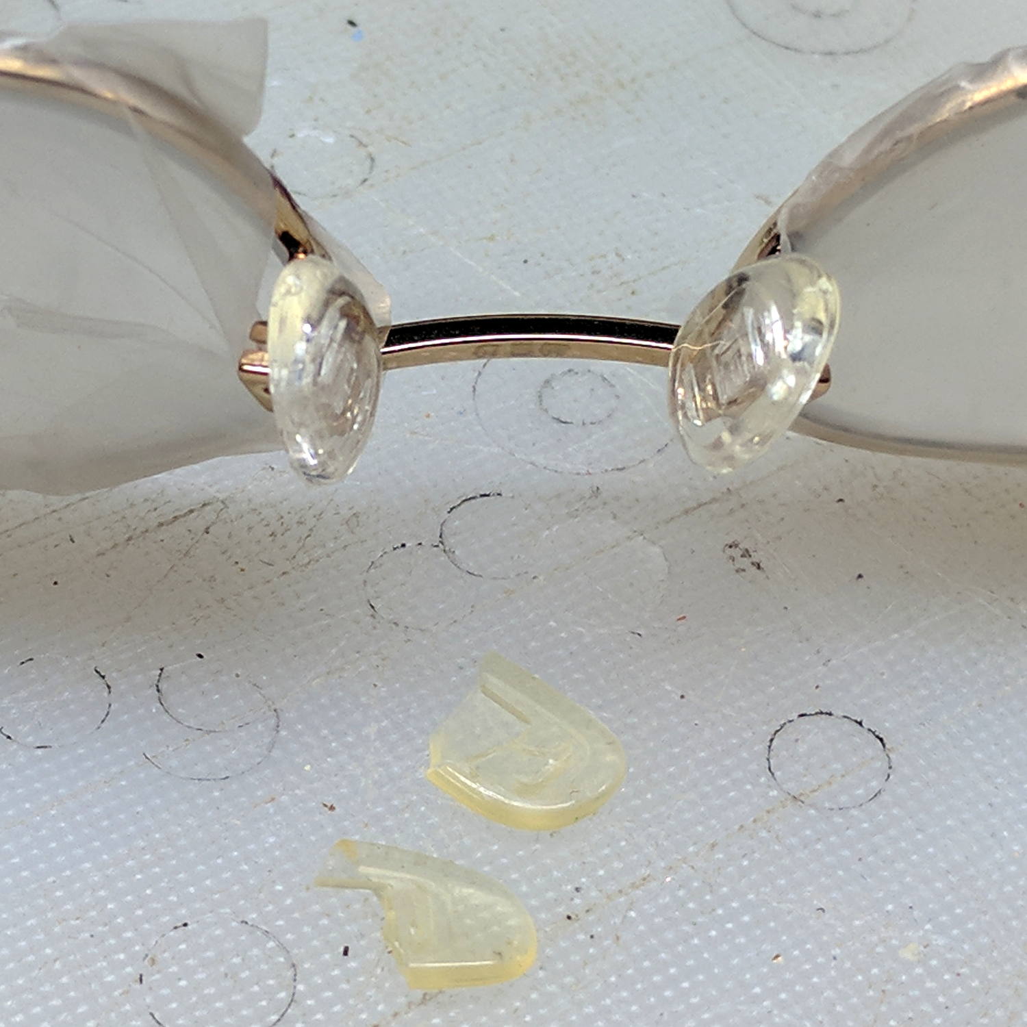
A stray nose pad appeared on the kitchen floor and, after some investigation, it corresponded with the stub in Mary’s oldest reading glasses. Some rummaging in the Bag o’ Eyeglass Stuff produced a similar pair of pads:
Glasses – missing nose pad
Although the lenses have become somewhat scuffed over the years, masking the optics with Parafilm is always Good Practice:
Glasses – new nose pads – masked
The split boxes clamped around the pad stems required a bit of delicate opening-up with a utility knife blade before the new ones pressed firmly into place.
The O-rings on the spout of our American Standard kitchen faucet wore out again; having described that repair many times, there’s no need to say much more about it. I didn’t want to get into this repair while thinking about the hot limit problem, but I did check to make sure the box under the sink had some O-ring replacement kits.
A bench vise with soft jaws holds the spout while you remove the escutcheon ring retainer:
Kitchen faucet spout – in vise
Basically, just tap around the ring with a long drift punch and it’ll eventually fall out onto the reasonably clean rag below it.
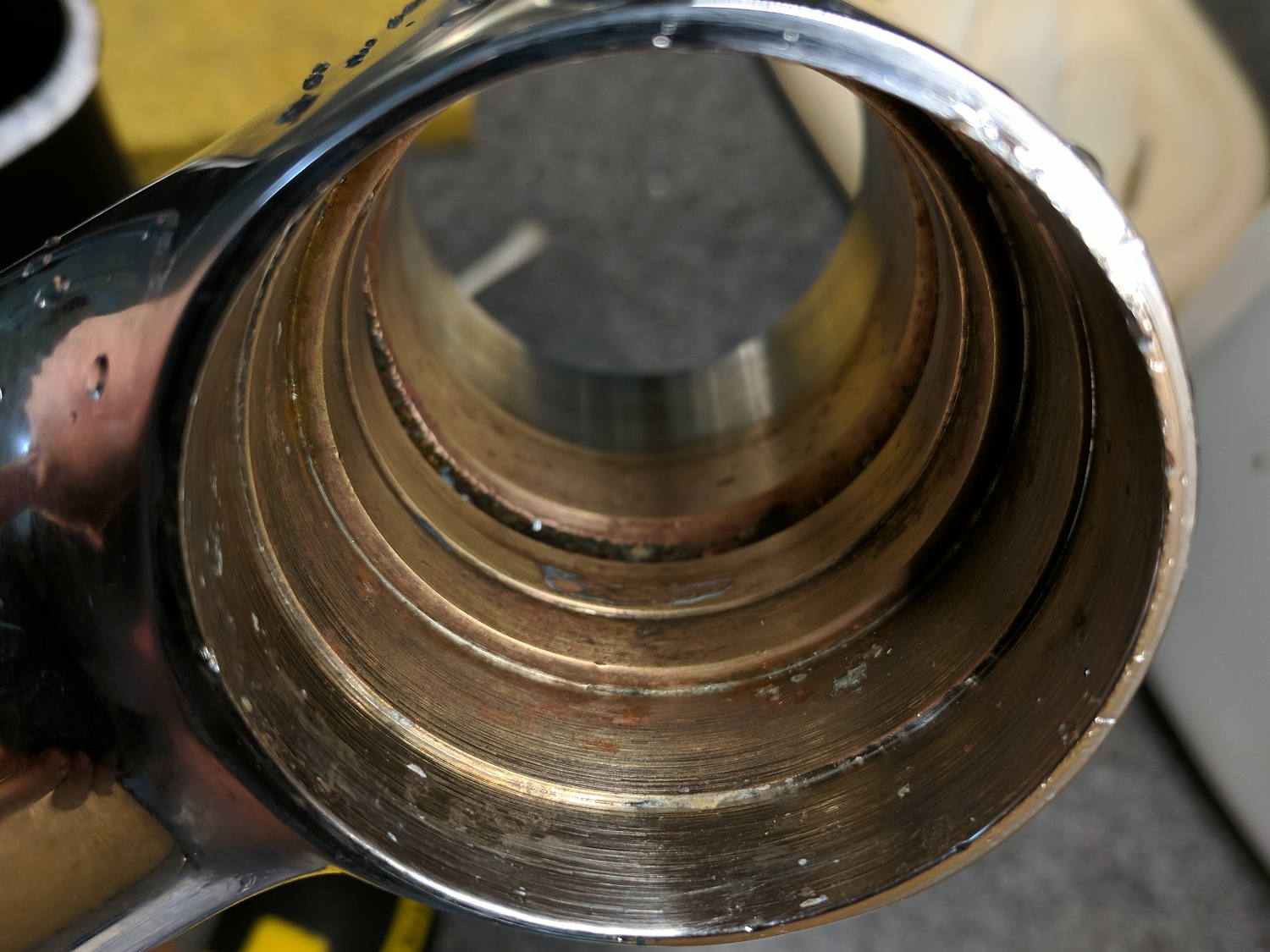
The interior of the spout before cleaning shows why you should never look into your plumbing:
Kitchen faucet spout interior – before
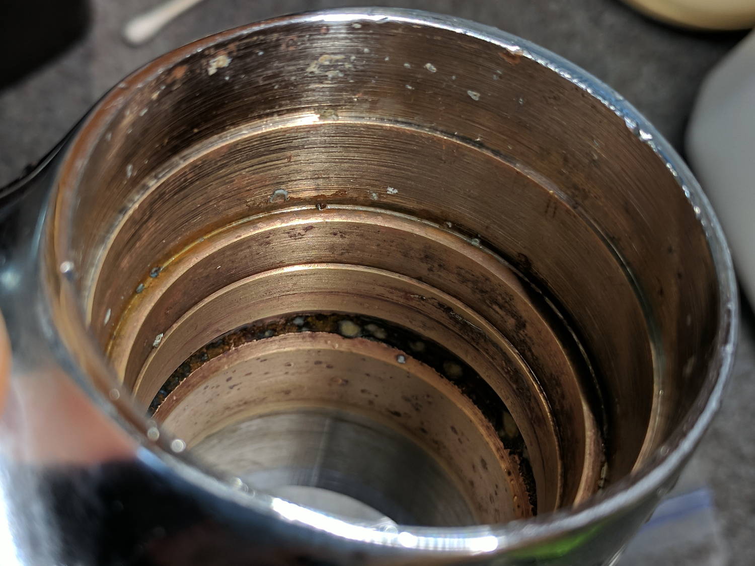
After a few hours in a white vinegar bath and a few minutes of scrubbing with a ScotchBrite pad:
Kitchen faucet spout interior – after – 1
Another view:
Kitchen faucet spout interior – after – 2
Obviously, you could do better, but it’s hard to get excited about the last few nodules. For whatever it’s worth, the nodules grow despite our water softener; I have no clue what’s going on in there.
A few wipes of silicone grease, reassemble in reverse order, apply a firm shove, and it’s leakless again. For a while, anyhow.
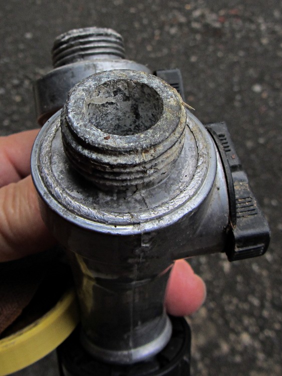
The corroded Y valve, minus another failed hose fitting, recently emerged from a heap o’ stuff on the Basement Laboratory Bench. This old photo gives you an idea of what happens to cheap pot metal in a garden:
Corroded Garden Y Valve
I dropped it Y-end-down into a container of white vinegar for a week, after which a few minutes of scrubbing produced a workable result:
Garden hose Y valve – after vinegar soak
The threads on the left side are pretty much gone. The hose fitting protected the threads on the right, but was corroded firmly in place; a penetrating oil soak and concerted muttering removed it.
All of the garden hoses and fittings out in Mary’s Vassar Farms plot have survived well beyond their best-used-by date. Given that we salvaged many hoses from the Farm’s end-of-season midden heaps, they don’t owe us much …
This eight-pointer was one of two browsing in the back-yard grove:
Eight point buck deer in velvet
The other was a mere four-pointer. In a few weeks they’ll get all feisty and browse the grove in shifts.
The notion of a “suburban hunting license”, perhaps with crossbows, may eventually gain traction.
A few days later, Mary awoke to a great clattering caused by a buck fighting free of the slot between the garden’s mesh “deer fence” and the neighbor’s wood fence, flattening the corner post in the process. A similar encounter a few years ago ended poorly.
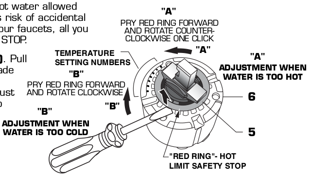
For the second time in a few months, the kitchen faucet handle stopped moving all the way to the left and the spout stopped dispensing hot water. The last time I did nothing and, after a few days, it resumed normal operation. Having had a while to think it over, this time I removed the handle and saw exactly what I expected:
American Standard Elite 4453 4454 faucet – hot limit stop diagram
The red ring (the “hot limit safety stop”) fits into one of eight click-stop positions; the photo shows it in position 5, with 0 being just to the right of the bottom screw and 7 just below the horizontal notch across the middle.
The dark gray plastic feature inside the ring connects the metal handle (the out-of-focus silver stud aimed at you) to the valve assembly. The two lugs sticking out to its left and right bump into the inward-pointing red lugs as you rotate the handle leftward = clockwise = more hot. With the ring set to the 0 position, the red lugs overlap similar lugs molded into the light gray valve body that limit the rotation in both directions.
Observations:
You must pry the red ring upward to disengage the splines locking it into position
The gray lugs impose a hard stop in the counterclockwise direction = cold
There’s no upward force on the ring for any reason that I can imagine
We don’t pound on the faucet handle, so there’s no shock loading
I have no idea how the red ring could disengage its splines and move counterclockwise by five clicks all by itself.
I reset it to 0, reassembled the faucet with a dot of penetrating oil in the set screw, and it’s all good.
Earlier this year, I finally hauled a pile o’ scrap metal to the recycler. For future reference, here’s what clattered down on the scale:
Scrap Metal Prices – 2017-04
I think the IRONY tag means ferrous bits & pieces in the mix. There’s a powerful motivation to hand them clean copper scrap, although I stop just after cutting off soldered pipe fittings and before stripping insulation.
Memo to Self: Next time, ask about PCBs and gold-plated connectors.
Right now, it’s a two-day-old cross-striped cabbageworm. Its kin are voracious consumers of Brassicacae out in the garden and Mary’s raising it as a show-n-tell exhibit for her Master Gardener compadres; she advised it to not start any long novels.