Ed Nisley's Blog: Shop notes, electronics, firmware, machinery, 3D printing, laser cuttery, and curiosities. Contents: 100% human thinking, 0% AI slop.
The gotcha happens when the USB port doesn’t become available, in which case the conditional remains true and the loop continues forever, which is precisely what happened when I powered the Teensy from a USB battery pack on the Squidwrench Operating Table.
After some flailing around, this startup snippet falls through after ahem awhile:
#define BUILTIN_LED 13

... snippage ...

Serial.begin(115200);

int waited = 0;
while (!Serial && waited < 3000) {
  delay(1);
  waited++;
  if (! (waited % 50))
    FlipPin(BUILTIN_LED);
}

... snippage ...

Serial.printf(" serial wait: %d ms\n\n",waited);
The serial startup delay seems to vary unpredictably between 800 and 1800 ms, so 3000 ms may be too short:
serial wait: 1033 ms
serial wait: 899 ms
serial wait: 907 ms
The ARM Teensy connects the board's built-in LED to the same SPI clock as on the AVR Arduinos, so it's only useful during startup, but having some hint will come in handy the next time it jams for another reason.
Doing the DDS calculations in full-frontal double floating point turns out to be maybe fast enough:
DDS Mock – 0 VAC – SPI
I set the ADC to HIGH_SPEED conversion and sampling, reducing the time between the start of conversion (first pulse in D1) and the ADC end-of-conversion interrupt (rising edge in D2) from 4.7 μs to 2.6 μs, more-or-less, kinda-sorta.
The ADC hardware can return the average of several sample taken in quick succession, so I set it to average four samples. The vertical cursors show the combination of fast conversion and averaging requires 7 μs (-ish) from start to finish: long enough to justify separating the two by an interrupt and short enough to allow calculations after fetching the result.
The purple trace shows the analog input voltage hovering close to a constant VCC/2 (about 1.6+ V), rather than the sine-wave I used earlier, again courtesy of the scope’s arbitrary function generator. The loop() dumps the min and max ADC values (minus half the ADC range (4096/2= 2048):
    -4 to     2
    -3 to     2
    -3 to     2
A span of half a dozen counts = 3 bits means the 12 bit ADC really delivers 9 bits = 0.2% resolution = 54 dB dynamic range = probably not good enough. However, the “circuit” is an open-air hairball on the bench, driven from the scope’s arbitrary waveform generator in high-Z mode, so things can only get better with more any attention to detail.
The 1.9 μs gap between the first and second burst of SPI clocks contains all the floating-point calculations required to convert an ADC sample to DDS delta-phase bits:
void adc0_isr(void) {

  int Audio;

  digitalWriteFast(PIN_ANALOG,HIGH);

  AnalogSample = adc->readSingle();             	  // fetch just-finished sample
  Audio = AnalogSample - 2048;                      // convert to AC signal

  DDSBuffer.Phase = 0;

  SPI.beginTransaction(SPISettings(8000000, MSBFIRST, SPI_MODE0));
  digitalWriteFast(PIN_DDS_FQUD, LOW);

  SPI.transfer(DDSBuffer.Phase);

  DDSBuffer.DeltaPhase = (uint32_t)((((double)Audio / 2048.0) * Deviation + Crystal) * CountPerHertz);

  SPI.transfer((uint8_t)(DDSBuffer.DeltaPhase >> 24));      // MSB first!

  if (Audio > AudioMax)                                     // ignore race conditions
    AudioMax = Audio;
  if (Audio < AudioMin) AudioMin = Audio; SPI.transfer((uint8_t)(DDSBuffer.DeltaPhase >> 16));

  SPI.transfer((uint8_t)(DDSBuffer.DeltaPhase >>  8));
  SPI.transfer((uint8_t)DDSBuffer.DeltaPhase);

  SPI.endTransaction();                         // do not raise FQ_UD until next timer tick!

  digitalWriteFast(PIN_ANALOG,LOW);
}
A closer look lets the scope decode and present the SPI data:
DDS Mock – 0 VAC – SPI detail
The program calculates and displays various “constants” I set for convenience:
FM Modulated DDS
Ed Nisley KE4ZNU
 serial wait: 890 ms

DDS clock:     180000000.000 Hz
CountPerHertz:        23.861 ct
HertzPerCount:         0.042 Hz

Crystal:    20000000.000 Hz
Deviation:      5000.000 Hz
You can confirm the SPI data by working backwards with a calculator:
This file contains hidden or bidirectional Unicode text that may be interpreted or compiled differently than what appears below. To review, open the file in an editor that reveals hidden Unicode characters.
Learn more about bidirectional Unicode characters
Inserting a few simple floating point operations between the SPI transfers provides a quick-n-dirty look at the timings:
Math timing – double ops
The corresponding code runs in the ADC end-of-conversion handler:
void adc0_isr(void) {

  digitalWriteFast(ANALOG_PIN,HIGH);

  AnalogSample = adc->readSingle();                     // fetch just-finished sample

  SPI.beginTransaction(SPISettings(8000000, MSBFIRST, SPI_MODE0));
  digitalWriteFast(DDS_FQUD_PIN, LOW);

  SPI.transfer(DDSBuffer.Phase);                // interleave with FM calculations
  FlipPin(GLITCH_PIN);
  TestFreq += DDSStepFreq;
  FlipPin(GLITCH_PIN);
  SPI.transfer(DDSBuffer.Bits31_24);
  TestFreq -= DDSStepFreq;
  SPI.transfer(DDSBuffer.Bits23_16);
  TestFreq *= DDSStepFreq;
  SPI.transfer(DDSBuffer.Bits15_8);
  FlipPin(GLITCH_PIN);
  TestFreq /= DDSStepFreq;
  FlipPin(GLITCH_PIN);
  SPI.transfer(DDSBuffer.Bits7_0);
  SPI.endTransaction();                         // do not raise FQ_UD until next timer tick!

  digitalWriteFast(ANALOG_PIN,LOW);
}
The FlipPin() function twiddling the output bit takes a surprising amount of time, as shown by the first two gaps in the blocks of SPI clocks (D4). Some cursor fiddling on a zoomed scale says 300 ns = 50-ish cycles for each call. In round numbers, actual code doing useful work will take longer than that.
Double precision floating add / subtract / multiply seem to take about 600 ns. That’s entirely survivable if you don’t get carried away.
Double precision division, on the other paw, eats up 3 μs = 3000 ns, so it’s not something you want to casually plunk into an interrupt handler required to finish before the next audio sample arrives in 20 μs.
Overall, the CPU utilization seems way too high for comfort, mostly due to the SPI transfers, even without any computation. I must study the SPI-by-DMA examples to see if it’s a win.
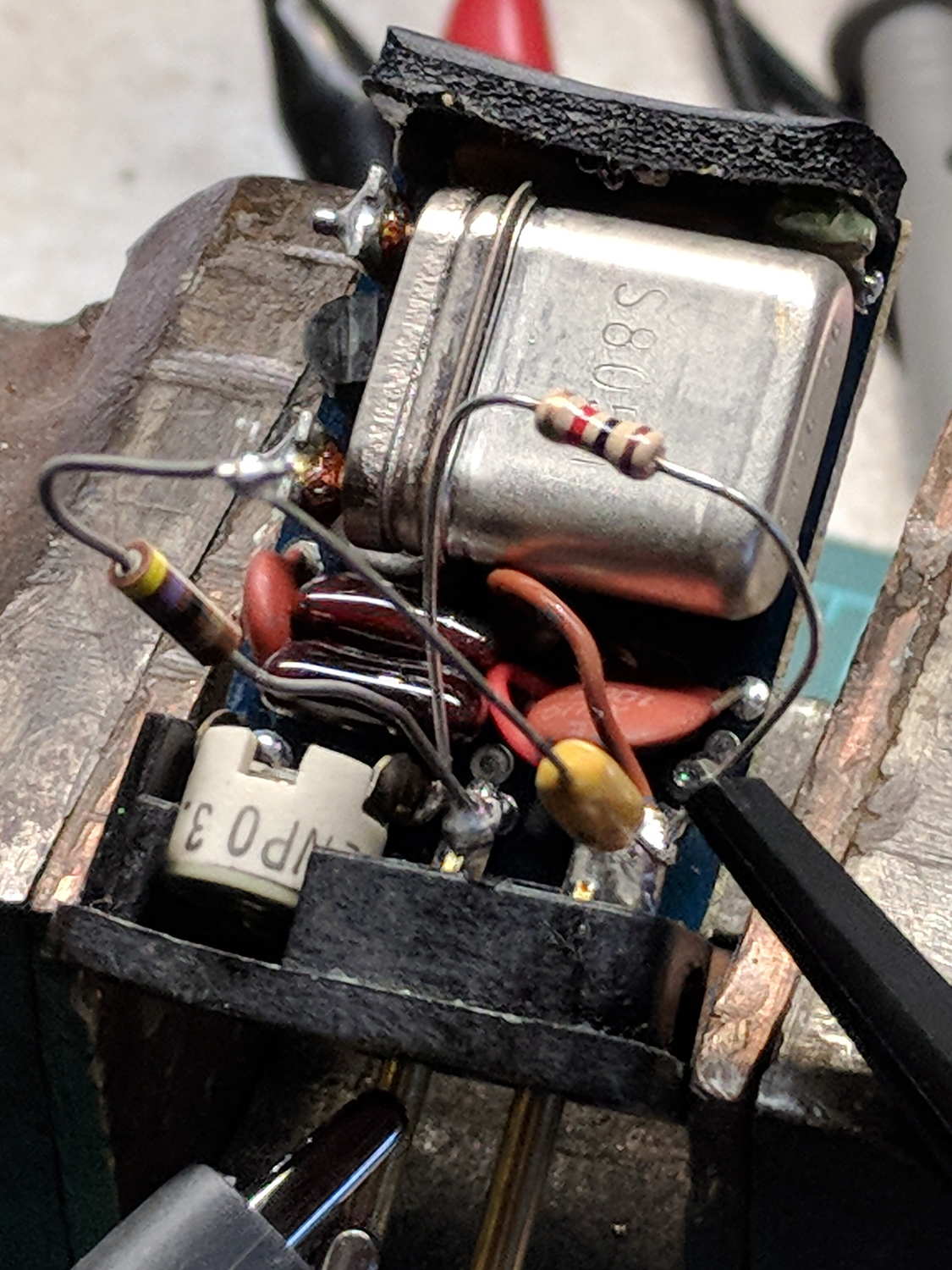
For lack of anything smarter, I put a 1 kΩ resistor from RF Out to Ground to get some DC current going, then used a 470 nF cap and 47 Ω resistor as an AC load:
K1003 Channel Element – bias lashup
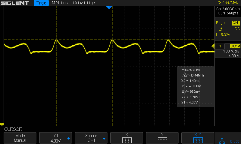
Which oscillated around a mid-scale DC bias, but looked ugly:
K1003 Channel Element – 13.4 MHz output – 1k bias
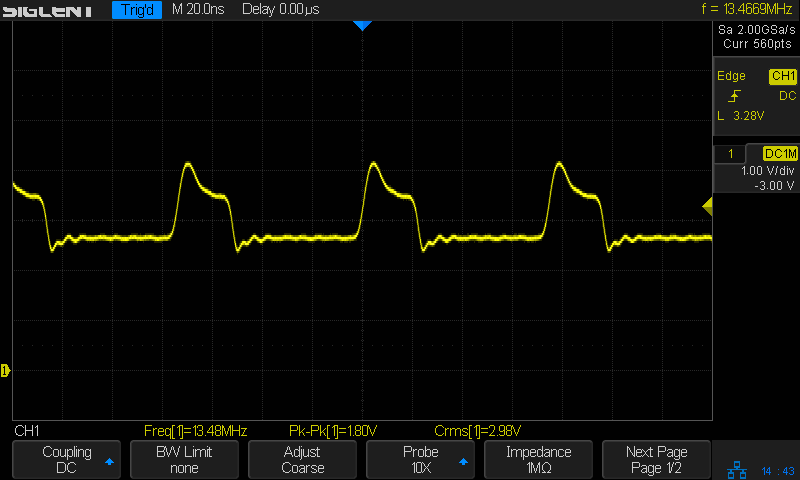
Perusing some receiver schematics suggested a heavier DC load, so I swapped in a 470 Ω resistor:
The general idea is to frequency modulate the sine wave coming from a DDS, thereby generating a signal suitable for upconverting in amateur repeaters now tied to unobtainable crystals. The crystals run from 4-ish to 20-ish MHz, with frequency multiplication from 3 to 36 producing RF outputs from 30-ish MHz through 900-ish MHz; more details as I work through the choices.
The demo code runs on a bare Teensy 3.6 as a dipstick test for the overall timing and functionality:
FM DDS – Teensy 3.6 SPI demo
The fugliest thing you’ve seen in a while, eh?
An overview of the results:
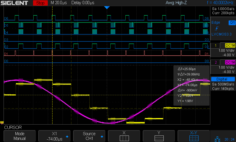
Analog 4 kHz @ 40 kHz – SPI demo overview
The pulses in D1 (orange digital) mark timer ticks at a 40 kHz pace, grossly oversampling the 4 kHz audio bandwidth in the hope of trivializing the antialiasing filters. The timer tick raises the DDS latch pin (D6, top trace) to change the DDS frequency, fires off another ADC conversion, and (for now) copies the previous ADC value to the DAC output:
The purple analog trace is the input sine wave at 4 kHz. The yellow analog stairstep comes from the DAC, with no hint of a reconstruction filter knocking off the sharp edges.
The X1 cursor (bold vertical dots) marks the start of the ADC read. I hope triggering it from the timer tick eliminates most of the jitter.
The Y1 cursor (upper dotted line, intersecting X1 just left of the purple curve) shows the ADC sample apparently happens just slightly after the conversion. The analog scales may be slightly off, so I wouldn’t leap to any conclusions.
The pulses in D2 mark the ADC end-of-conversion interrupts:
void adc0_isr(void) {
  digitalWriteFast(ANALOG_PIN,HIGH);
  AnalogSample = adc->readSingle();                     // fetch just-finished sample
  SPI.beginTransaction(SPISettings(8000000, MSBFIRST, SPI_MODE0));
  digitalWriteFast(DDS_FQUD_PIN, LOW);
  SPI.transfer(DDSBuffer.Phase);                // interleave with FM calculations
  SPI.transfer(DDSBuffer.Bits31_24);
  SPI.transfer(DDSBuffer.Bits23_16);
  SPI.transfer(DDSBuffer.Bits15_8);
  SPI.transfer(DDSBuffer.Bits7_0);
  SPI.endTransaction();                         // do not raise FQ_UD until next timer tick!
  digitalWriteFast(ANALOG_PIN,LOW);
}
The real FM code will multiply the ADC reading by the amplitude-to-frequency-deviation factor, add it to the nominal “crystal” frequency, convert the sum to the DDS delta-phase register value, then send it to the DDS through the SPI port. For now, I just send five constant bytes to get an idea of the minimum timing with the SPI clock ticking along at 8 MHz.
The tidy blurs in D4 show the SPI clock, with the corresponding data in D5.
D6 (top trace) shows the DDS FQ_UD (pronounced “frequency update”) signal dropping just before the SPI data transfer begins. Basically, FQ_UD is the DDS Latch Clock: low during the delta-phase value transfer, with the low-to-high transition latching all 40 control + data bits into the DDS to trigger the new frequency.
A closer look at the sample and transfer:
Analog 4 kHz @ 40 kHz – SPI demo detail
For reference, the digital players from bottom to top:
D0 – unused here, shows pulses marking main loop
D1 – 40 kHz timer ticks = ADC start conversion
D2 – ADC end of conversion,”FM calculation”, send DDS data
D3 – unused here, shows error conditions
D4 – SPI clock = rising edge active
D5 – SPI MOSI data to DDS = MSB first
D6 – SPI CS = FQ_UD = DDS latch
Remember, the yellow analog stairstepped trace is just a comfort signal showing the ADC actually samples the intended input.
Dropping the sampling to 20 kHz would likely work just as well and double the time available for calculations. At least now I can measure what’s going on.
All in all, it looks feasible.
And, yes, the scope is a shiny new Siglent SDS2304X with the MSO logic-analyzer option. It has some grievous UX warts & omissions suggesting an architectural botch job, but it’s mostly Good Enough for what I need. More later.
This file contains hidden or bidirectional Unicode text that may be interpreted or compiled differently than what appears below. To review, open the file in an editor that reveals hidden Unicode characters.
Learn more about bidirectional Unicode characters