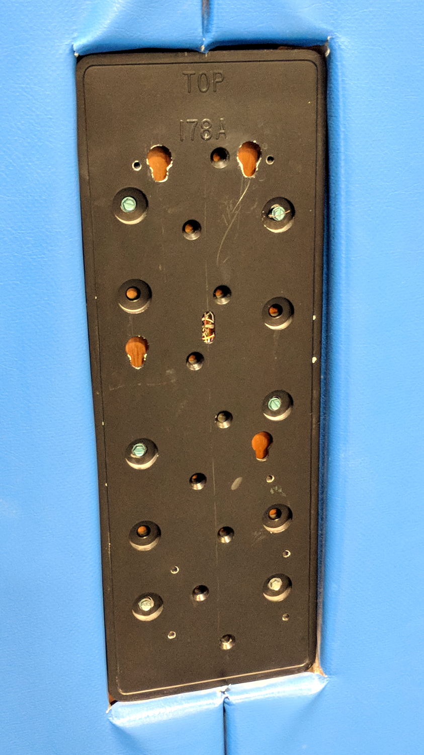
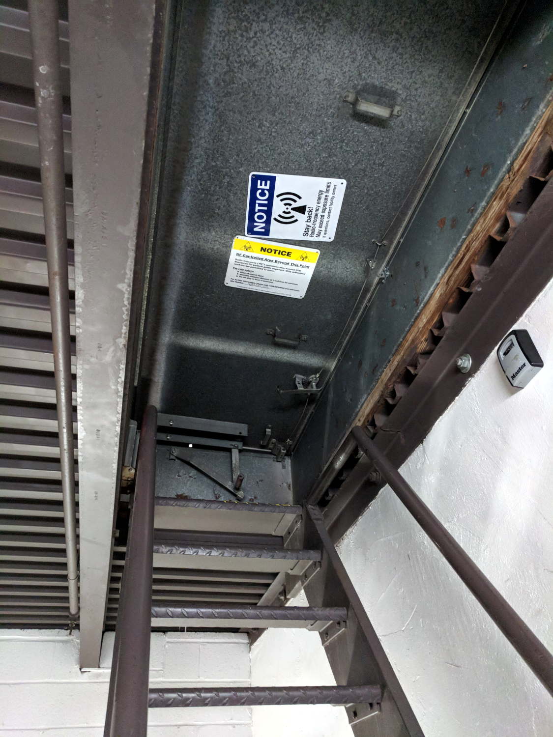
Spotted this at the top of a motel stairwell:

More detail:

The antennas face away from the hatch, so it’s not as if the RF would shear you off as you climbed through:

I wonder if the hatch atop Vassar Main sports a similar warning …
The Smell of Molten Projects in the Morning
Ed Nisley's Blog: Shop notes, electronics, firmware, machinery, 3D printing, laser cuttery, and curiosities. Contents: 100% human thinking, 0% AI slop.
Electrical & Electronic gadgets
Spotted this at the top of a motel stairwell:

More detail:

The antennas face away from the hatch, so it’s not as if the RF would shear you off as you climbed through:

I wonder if the hatch atop Vassar Main sports a similar warning …
Running some serial I/O in the background adds jitter to the timer interrupt pacing the ADC samples and as-yet-unwired DDS updates. For reference, an overview of the process showing the procession from the IRQ on the left to the SPI outputs near the middle and another IRQ on the far right:

Now, speed up the sweep and delay the trace by 25 μs to put the triggering pulse off-screen to the left and the second pulse at the center division:

The orange smear in the middle should be a tidy pulse, but it isn’t.
The 25 μs timer interrupt now has the highest priority on the front burner:
IntervalTimer AudioSampler;
... snippage ...
AudioSampler.priority(0);
if (!AudioSampler.begin(AudioSamplerIRQ, SamplePeriod)) {
Serial.printf("Timer start failed\n");
while (true) {
FlipPin(BUILTIN_LED);
delay(75);
}
}
Although nothing can interrupt it, other code / handlers may disable interrupts around their own critical sections and delay the tick. If the triggering tick (the off-screen one starting the trace) is delayed, then the on-screen pulse will appear “too soon”, to the left of center. If the triggering tick is on time, but the on-screen pulse is delayed, it’ll appear “too late” on the right.
The blur is (roughly) symmetric around the center graticule line, so the handwaving seems about right.
In round numbers, the jitter moves the interrupt ±325 ns on either side of its nominal position, with most of the pulses within ±100 ns. I doubt the jitter distribution is Gaussian, but vigorous handwaving says the RMS jitter might amount to 75 ns.
At the 4 kHz audio band limit, a 75 ns sampling error a phase error of 0.1°, so the maximum amplitude jitter would be sin(0.1°) = 0.002 = -55 dB, which might suffice for amateur-radio audio.
I think, anyhow.
The SPI OLEDs continue to misbehave, with this early morning glitch jamming the display into a complete lockup:

A normal, albeit blind, shutdown-and-reset brought it back to life.
Other OLEDs on other RPis have occasionally misbehaved since the most recent (attempted) tweak, so it hasn’t made any difference.
One obvious lesson: prefer OLEDs with I2C interfaces.
The Arduino Serial doc says the USB hardware on the (now obsolescent) Leonardo requires a test-for-open before using the serial port:
Serial.begin(9600);
while (!Serial) {
; // wait for serial port to connect. Needed for native USB
}
}
As it happens, you must also use that test on the ARM-based Teensy 3.6.
The gotcha happens when the USB port doesn’t become available, in which case the conditional remains true and the loop continues forever, which is precisely what happened when I powered the Teensy from a USB battery pack on the Squidwrench Operating Table.
After some flailing around, this startup snippet falls through after ahem awhile:
#define BUILTIN_LED 13
... snippage ...
Serial.begin(115200);
int waited = 0;
while (!Serial && waited < 3000) {
delay(1);
waited++;
if (! (waited % 50))
FlipPin(BUILTIN_LED);
}
... snippage ...
Serial.printf(" serial wait: %d ms\n\n",waited);
The serial startup delay seems to vary unpredictably between 800 and 1800 ms, so 3000 ms may be too short:
serial wait: 1033 ms
serial wait: 899 ms
serial wait: 907 ms
The ARM Teensy connects the board's built-in LED to the same SPI clock as on the AVR Arduinos, so it's only useful during startup, but having some hint will come in handy the next time it jams for another reason.
Doing the DDS calculations in full-frontal double floating point turns out to be maybe fast enough:

I set the ADC to HIGH_SPEED conversion and sampling, reducing the time between the start of conversion (first pulse in D1) and the ADC end-of-conversion interrupt (rising edge in D2) from 4.7 μs to 2.6 μs, more-or-less, kinda-sorta.
The ADC hardware can return the average of several sample taken in quick succession, so I set it to average four samples. The vertical cursors show the combination of fast conversion and averaging requires 7 μs (-ish) from start to finish: long enough to justify separating the two by an interrupt and short enough to allow calculations after fetching the result.
The purple trace shows the analog input voltage hovering close to a constant VCC/2 (about 1.6+ V), rather than the sine-wave I used earlier, again courtesy of the scope’s arbitrary function generator. The loop() dumps the min and max ADC values (minus half the ADC range (4096/2= 2048):
-4 to 2
-3 to 2
-3 to 2
A span of half a dozen counts = 3 bits means the 12 bit ADC really delivers 9 bits = 0.2% resolution = 54 dB dynamic range = probably not good enough. However, the “circuit” is an open-air hairball on the bench, driven from the scope’s arbitrary waveform generator in high-Z mode, so things can only get better with more any attention to detail.
The 1.9 μs gap between the first and second burst of SPI clocks contains all the floating-point calculations required to convert an ADC sample to DDS delta-phase bits:
void adc0_isr(void) {
int Audio;
digitalWriteFast(PIN_ANALOG,HIGH);
AnalogSample = adc->readSingle(); // fetch just-finished sample
Audio = AnalogSample - 2048; // convert to AC signal
DDSBuffer.Phase = 0;
SPI.beginTransaction(SPISettings(8000000, MSBFIRST, SPI_MODE0));
digitalWriteFast(PIN_DDS_FQUD, LOW);
SPI.transfer(DDSBuffer.Phase);
DDSBuffer.DeltaPhase = (uint32_t)((((double)Audio / 2048.0) * Deviation + Crystal) * CountPerHertz);
SPI.transfer((uint8_t)(DDSBuffer.DeltaPhase >> 24)); // MSB first!
if (Audio > AudioMax) // ignore race conditions
AudioMax = Audio;
if (Audio < AudioMin) AudioMin = Audio; SPI.transfer((uint8_t)(DDSBuffer.DeltaPhase >> 16));
SPI.transfer((uint8_t)(DDSBuffer.DeltaPhase >> 8));
SPI.transfer((uint8_t)DDSBuffer.DeltaPhase);
SPI.endTransaction(); // do not raise FQ_UD until next timer tick!
digitalWriteFast(PIN_ANALOG,LOW);
}
A closer look lets the scope decode and present the SPI data:

The program calculates and displays various “constants” I set for convenience:
FM Modulated DDS Ed Nisley KE4ZNU serial wait: 890 ms DDS clock: 180000000.000 Hz CountPerHertz: 23.861 ct HertzPerCount: 0.042 Hz Crystal: 20000000.000 Hz Deviation: 5000.000 Hz
You can confirm the SPI data by working backwards with a calculator:
Nicely inside the range of values reported by the main loop, whew.
Which means I can avoid screwing around with fixed-point arithmetic until such time as clawing back a few microseconds makes a meaningful difference.
Now, to begin paying attention to those pesky hardware details …
The TeensyDuino source code as a GitHub Gist:
| // FM DDS | |
| // Ed Nisley – KE4ZNU | |
| // 2017-04-19 Demo 1 | |
| #include <IntervalTimer.h> | |
| #include <ADC.h> | |
| #include <SPI.h> | |
| #define PIN_HEART 14 | |
| #define PIN_TIMER 15 | |
| #define PIN_ANALOG 16 | |
| #define PIN_GLITCH 17 | |
| #define PIN_AUDIO A9 | |
| #define PIN_DDS_FQUD 10 | |
| // data to DDS MOSI0 11 | |
| // no data from DDS MISO0 12 | |
| // DDS clock on SCK0 13 — also LED | |
| #define BUILTIN_LED 13 | |
| //——————— | |
| // Useful constants | |
| int SamplePeriod = 25; // microseconds per analog sample | |
| //——————— | |
| // Globals | |
| ADC *adc = new ADC(); | |
| IntervalTimer timer; | |
| volatile int AnalogSample; | |
| volatile int AudioMax = -4096; | |
| volatile int AudioMin = 4096; | |
| typedef struct { | |
| uint8_t Phase; | |
| uint32_t DeltaPhase; // DDS expects MSB first! | |
| } DDS; | |
| DDS DDSBuffer; | |
| double DDSClock = 180.0e6; // nominal DDS oscillator | |
| double CountPerHertz, HertzPerCount; // DDS delta-phase increments | |
| double Crystal = 20.0e6; // nominal DDS frequency | |
| double Deviation = 5.0e3; // nominal FM signal deviation (one-sided) | |
| double TestFreq; | |
| //——————— | |
| // Handy routines | |
| void FlipPin(int pin) { | |
| digitalWriteFast(pin,!digitalRead(pin)); | |
| } | |
| void PulsePin(int p) { | |
| FlipPin(p); | |
| FlipPin(p); | |
| } | |
| //——————— | |
| // Timer handler | |
| void timer_callback(void) { | |
| digitalWriteFast(PIN_TIMER,HIGH); | |
| digitalWriteFast(PIN_DDS_FQUD,HIGH); // latch previously shifted bits | |
| adc->startSingleRead(PIN_AUDIO, ADC_0); // start ADC conversion | |
| analogWriteDAC0(AnalogSample); // show previous audio sample | |
| digitalWriteFast(PIN_TIMER,LOW); | |
| } | |
| //——————— | |
| // Analog read handler | |
| void adc0_isr(void) { | |
| int Audio; | |
| digitalWriteFast(PIN_ANALOG,HIGH); | |
| AnalogSample = adc->readSingle(); // fetch just-finished sample | |
| Audio = AnalogSample – 2048; // convert to AC signal | |
| DDSBuffer.Phase = 0; | |
| SPI.beginTransaction(SPISettings(8000000, MSBFIRST, SPI_MODE0)); | |
| digitalWriteFast(PIN_DDS_FQUD, LOW); | |
| SPI.transfer(DDSBuffer.Phase); | |
| DDSBuffer.DeltaPhase = (uint32_t)((((double)Audio / 2048.0) * Deviation + Crystal) * CountPerHertz); | |
| SPI.transfer((uint8_t)(DDSBuffer.DeltaPhase >> 24)); // MSB first! | |
| if (Audio > AudioMax) // ignore race conditions | |
| AudioMax = Audio; | |
| if (Audio < AudioMin) | |
| AudioMin = Audio; | |
| SPI.transfer((uint8_t)(DDSBuffer.DeltaPhase >> 16)); | |
| SPI.transfer((uint8_t)(DDSBuffer.DeltaPhase >> 8)); | |
| SPI.transfer((uint8_t)DDSBuffer.DeltaPhase); | |
| SPI.endTransaction(); // do not raise FQ_UD until next timer tick! | |
| digitalWriteFast(PIN_ANALOG,LOW); | |
| } | |
| //——————— | |
| // Hardware setup | |
| void setup(void) { | |
| pinMode(BUILTIN_LED,OUTPUT); // will eventually become SCK0 | |
| pinMode(PIN_HEART, OUTPUT); // show we arrived | |
| digitalWrite(PIN_HEART,LOW); | |
| PulsePin(PIN_HEART); | |
| PulsePin(PIN_HEART); | |
| pinMode(PIN_TIMER,OUTPUT); | |
| digitalWrite(PIN_TIMER,LOW); | |
| pinMode(PIN_GLITCH,OUTPUT); | |
| digitalWrite(PIN_GLITCH,LOW); | |
| pinMode(PIN_ANALOG,OUTPUT); | |
| digitalWrite(PIN_ANALOG,LOW); | |
| pinMode(PIN_AUDIO,INPUT); | |
| pinMode(PIN_DDS_FQUD,OUTPUT); | |
| digitalWriteFast(PIN_DDS_FQUD,HIGH); | |
| Serial.begin(115200); | |
| int waited = 0; | |
| while (!Serial && waited < 3000) { // fall out after a few seconds | |
| delay(1); | |
| waited++; | |
| if (! (waited % 50)) | |
| FlipPin(BUILTIN_LED); | |
| } | |
| Serial.printf("FM Modulated DDS\nEd Nisley KE4ZNU\n"); | |
| Serial.printf(" serial wait: %d ms\n\n",waited); | |
| SPI.begin(); | |
| SPI.usingInterrupt(255); // attached through analog IRQs | |
| adc->setAveraging(4); // choices: 0, 4, 8, 16, 32 | |
| adc->setResolution(12); // choices: 8, 10, 12, 16 | |
| adc->setConversionSpeed(ADC_CONVERSION_SPEED::HIGH_SPEED); | |
| adc->setSamplingSpeed(ADC_SAMPLING_SPEED::HIGH_SPEED); | |
| adc->enableInterrupts(ADC_0); | |
| if (!timer.begin(timer_callback, SamplePeriod)) { | |
| Serial.printf("Timer start failed\n"); | |
| while (true) { | |
| FlipPin(BUILTIN_LED); | |
| delay(75); | |
| } | |
| } | |
| CountPerHertz = (1LL << 32) / DDSClock; | |
| HertzPerCount = 1.0 / CountPerHertz; | |
| Serial.printf("DDS clock: %13.3f Hz\n",DDSClock); | |
| Serial.printf("CountPerHertz: %13.3f ct\n",CountPerHertz); | |
| Serial.printf("HertzPerCount: %13.3f Hz\n\n",HertzPerCount); | |
| TestFreq = Crystal; | |
| Serial.printf("Crystal: %13.3f Hz\n",Crystal); | |
| Serial.printf("Deviation: %13.3f Hz\n",Deviation); | |
| Serial.printf("\nSetup done\n"); | |
| } | |
| //——————— | |
| // Do things forever | |
| void loop(void) { | |
| digitalWrite(PIN_HEART,HIGH); | |
| Serial.printf(" %5d to %5d\n",AudioMin,AudioMax); | |
| AudioMax = 99*AudioMax/100; // ignore race conditions | |
| AudioMin = 99*AudioMin/100; | |
| digitalWrite(PIN_HEART,LOW); | |
| delay(500); | |
| } |
Back in the day, HP scope probes had a rugged music-wire hook on the tip:

These days, scope probe tips use ordinary sheet steel punched into a hook shape:

By sheer bad luck, the first probe out of the bag had a mis-punched end with no griptivity:

Dunno what happened, but it was definitely sheared off in the factory.
After I finally recognized the problem, I shaped a crude hook with a safe-edge needle file and continued the mission:

A quick note to Siglent put a replacement probe tip in the mail, so it’s all good.
Inserting a few simple floating point operations between the SPI transfers provides a quick-n-dirty look at the timings:

The corresponding code runs in the ADC end-of-conversion handler:
void adc0_isr(void) {
digitalWriteFast(ANALOG_PIN,HIGH);
AnalogSample = adc->readSingle(); // fetch just-finished sample
SPI.beginTransaction(SPISettings(8000000, MSBFIRST, SPI_MODE0));
digitalWriteFast(DDS_FQUD_PIN, LOW);
SPI.transfer(DDSBuffer.Phase); // interleave with FM calculations
FlipPin(GLITCH_PIN);
TestFreq += DDSStepFreq;
FlipPin(GLITCH_PIN);
SPI.transfer(DDSBuffer.Bits31_24);
TestFreq -= DDSStepFreq;
SPI.transfer(DDSBuffer.Bits23_16);
TestFreq *= DDSStepFreq;
SPI.transfer(DDSBuffer.Bits15_8);
FlipPin(GLITCH_PIN);
TestFreq /= DDSStepFreq;
FlipPin(GLITCH_PIN);
SPI.transfer(DDSBuffer.Bits7_0);
SPI.endTransaction(); // do not raise FQ_UD until next timer tick!
digitalWriteFast(ANALOG_PIN,LOW);
}
The FlipPin() function twiddling the output bit takes a surprising amount of time, as shown by the first two gaps in the blocks of SPI clocks (D4). Some cursor fiddling on a zoomed scale says 300 ns = 50-ish cycles for each call. In round numbers, actual code doing useful work will take longer than that.
Double precision floating add / subtract / multiply seem to take about 600 ns. That’s entirely survivable if you don’t get carried away.
Double precision division, on the other paw, eats up 3 μs = 3000 ns, so it’s not something you want to casually plunk into an interrupt handler required to finish before the next audio sample arrives in 20 μs.
Overall, the CPU utilization seems way too high for comfort, mostly due to the SPI transfers, even without any computation. I must study the SPI-by-DMA examples to see if it’s a win.