Ed Nisley's Blog: Shop notes, electronics, firmware, machinery, 3D printing, laser cuttery, and curiosities. Contents: 100% human thinking, 0% AI slop.
A friend now owns my trusty Canon SX230HS camera, but, given the restrictions on shipping lithium batteries, we agreed there was no point in transferring ownership of my nearly dead batteries.
For completeness, their final state:
Canon NB-5L – 2018-03-25
The original Canon OEM battery (orange curve) looms above all the offerings from various Amazon sellers.
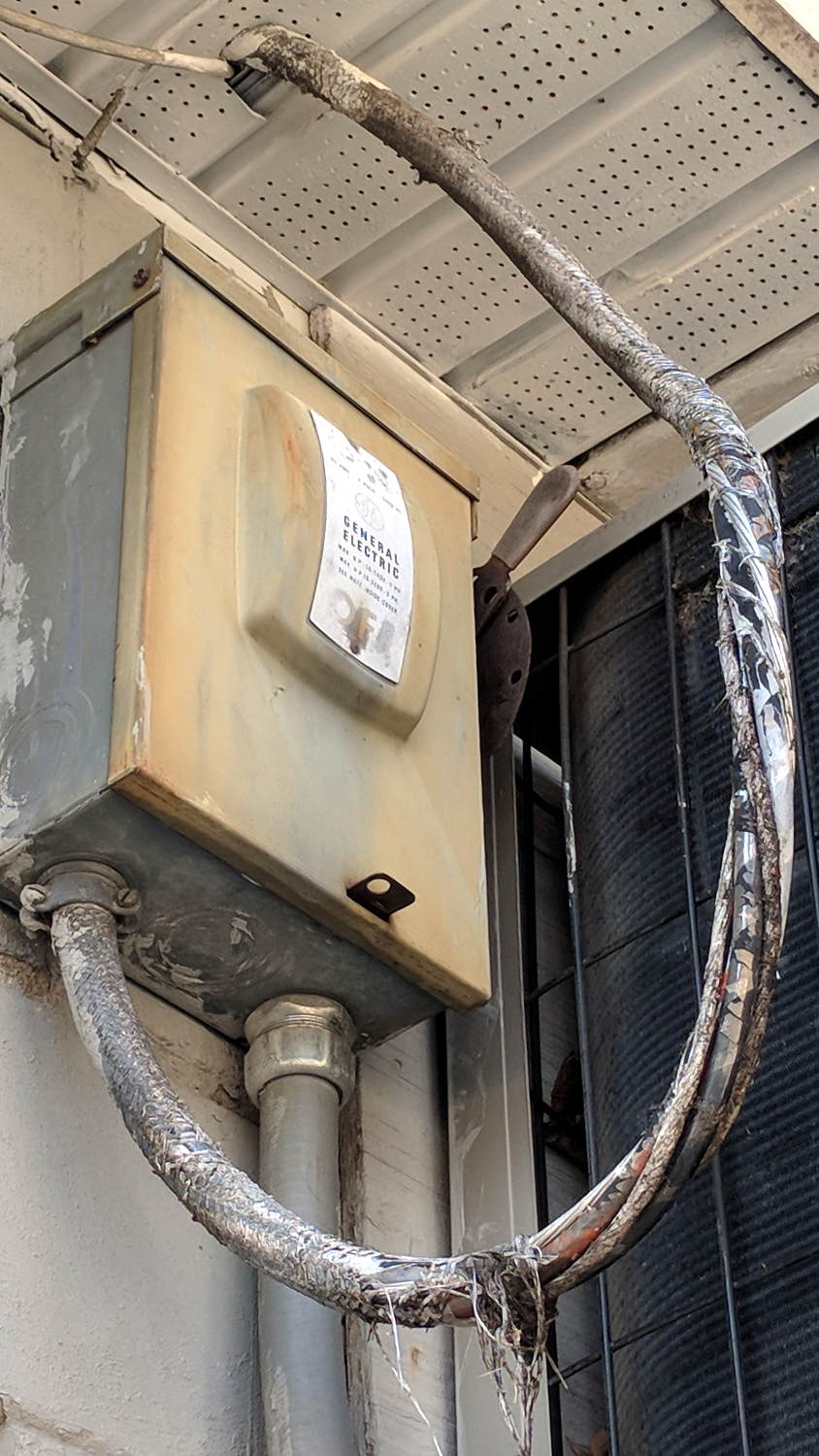
Spotted behind a small strip mall during one of our walks:
Rotted power cable
Perhaps the cable wasn’t rated for outdoor use?
The earth ground conductor isn’t insulated and the nonconductive filler strands look scary, but neither should kill you outright.
As far as I can tell, the insulation around the individual conductors remains intact, but it’s surely brittle and ready to fall off at the slightest touch.
The breaker box and cable are out of reach and, I suppose, out of mind.
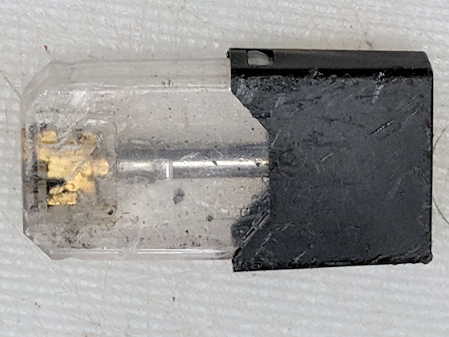
Being the kind of guy who lives under a rock, I thought this thing lying at the end of the driveway might be a USB widget:
Vape cartridge – side
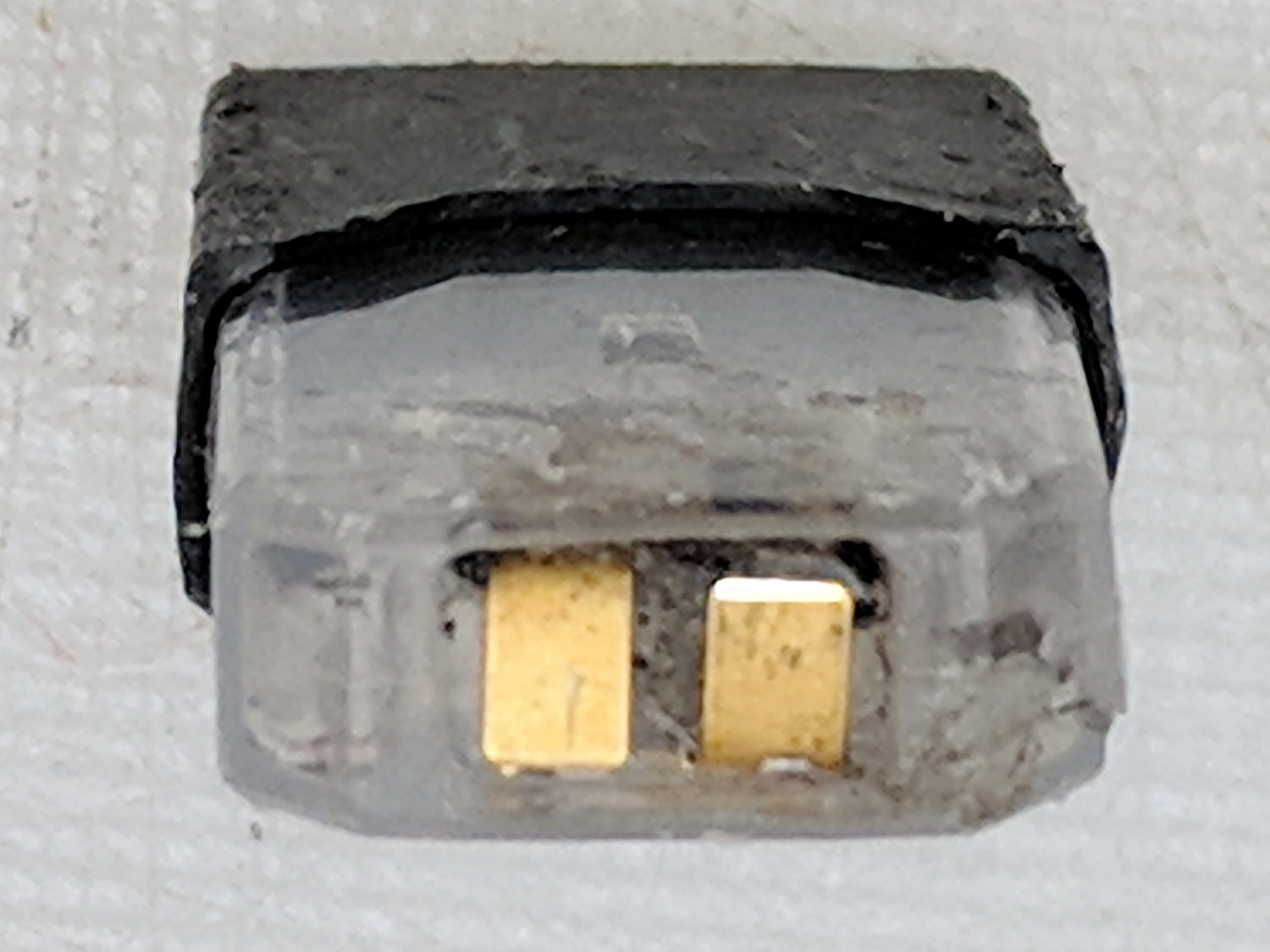
But the contacts are all wrong:
Vape cartridge – contacts
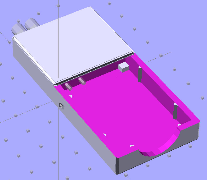
It has an opening on the other end:
Vape cartridge – exhaust port
An easy teardown produces a yard sale of parts:
Vape cartridge – components
The fiber snippet inside the coil carries the same sickly sweet scent as exhaled by passing vapers.
Some casual searching suggests it’s a Juul Vape Pod. The Juul site insists on lower browser armor than I’m willing to grant it; you’re on your own.
The heating coil press-fits into slots cut in the contacts:
Vape cartridge – heater and contacts
It’s about 1 Ω cold, so I foolishly assume there’s a current limiter somewhere in the circuitry.
The little steel tube goes into the Tray o’ Cutoffs, where it might come in handy some day, the debris hits the trash, and I washed my hands up to the elbows.
Ya learn something new every day around here and, obviously, I must get out more …
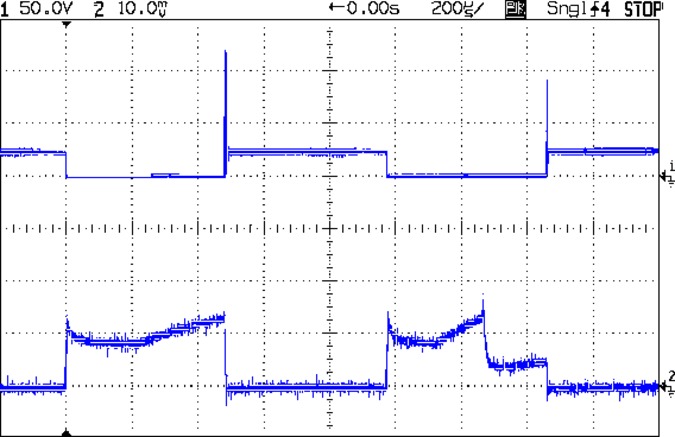
BLDC Blower – 24 V 1 kHz 50 pct 2600 RPM – 200 mA-div – sample B
The upper trace shows the MOSFET drain voltage, the lower trace is the current at 200 mA/div.
The fan is connected from +24 VDC to the drain, so it’s getting power when the MOSFET is turned on and the drain is at 0 V. When the MOSFET turns off, the drain goes high and the drain current flow stops dead in its tracks.
Of course, the fan current doesn’t drop to zero, because inductance. The drain voltage rises until the MOSFET body diode enters avalanche breakdown, whereupon the energy in the magnetic field burns down across the voltage difference as usual.
Weird current waveforms happen all the time:
BLDC Blower – 24 V 1 kHz 50 pct 2600 RPM – 200 mA-div – sample C
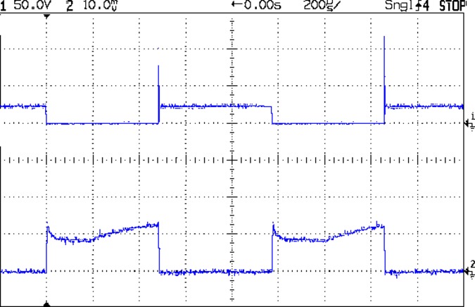
Or like this:
BLDC Blower – 24 V 1 kHz 50 pct 2600 RPM – 200 mA-div – sample A
I think we’re looking at a sensorless BLDC controller trying to figure out the fan RPM from the back EMF after rebooting during each PWM cycle.
In any event, the drain voltage in the upper trace tops out around 120 V, because the IRF530 MOSFET has a 100 V absolute maximum VDS spec: you’re watching avalanche breakdown happen. A transistor rated for 14 A of avalanche current isn’t in much danger quenching only 200 mA, though, so it’s all good, apart from slapping the fan with -100 V across what used to be its +24 V supply.
Eyeballometrically, the drain current decreases at 100 mA / 500 ns = 200 kA/s with the drain voltage clamped at 120 V, during the division just right of center. The other side of the fan sits at +24 VDC, so the effective inductance looks like 480 μH = 96 V / 200 kA/s. I’m unwilling to tear the blower apart just to measure the motor winding inductances.
In any event, because we’re seeing the output of a 24 V three-phase fan controller being reverse-biased at 100 V, I doubt those numbers mean anything, other than that you shouldn’t PWM-chop the current going into a BLDC fan controller, of course.
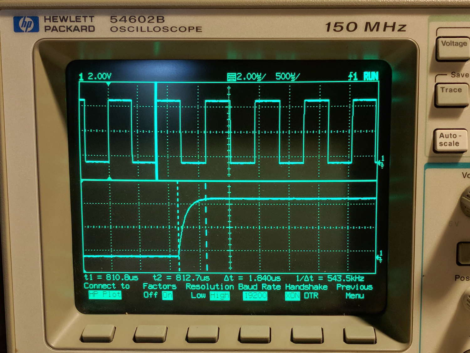
The objective is to capture screen shots from my HP 54602 oscilloscope, now connected to Serial Port 1 of the Sena PS410 serial server.
Although the scope command language offers a :PRINT? command, it produces output in HP PCL, from which there seems no practical way to get a raster image format like PNG. So this remains an output-only transfer triggered by poking the PRINT SCREEN softkey, after first setting the serial parameters:
HP 54602 scope serial parameters
In text:
Connect to: HP Plotter
Factors: ON
Resolution: HIGH
Baud rate: 19200 b/s
Handshake: XON
I have no idea what’s inside the serial cable at this late date (see the HP 8591 post for more musings), but the (paper!) manual says:
For three-wire operation, an XON/XOFF software handshake must be used to handle handshaking between the devices.
For extended hardwire operation, handshaking may be handled either with XON/XOFF or by manipulating the CTS and RTS lines of the oscilloscope.
For both three-wire and extended hardwire operation, the DCD and DSR inputs to the oscilloscope must remain high for proper operation.
With extended hardwire operation, a high on the CTS input allows the oscilloscope to send data and a low on this line disables the oscilloscope data transmission.
Likewise, a high on the RTS line allows the controller to send data and a low on this line signals a request for the controller to disable data transmission.
Since three-wire operation has no control over the CTS input, internal pull-up resistors in the oscilloscope ensure that this line remains high for proper three-wire operation.
Apparently, the DCD, DSR, and CTS inputs have internal pullups.
Hardware handshakings uses these signals:
Pin 4 RTS (Request To Send) is an output from the oscilloscope which can be used to control incoming data flow.
Pin 5 CTS (Clear To Send) is an input to the oscilloscope which controls data flow from the oscilloscope.
Pin 6 DSR (Data Set Ready) is an input to the oscilloscope which controls data flow from the oscilloscope within two bytes.
Pin 8 DCD (Data Carrier Detect) is an input to the oscilloscope which controls data flow from the oscilloscope within two bytes.
Pin 20 DTR (Data Terminal Ready) is an output from the oscilloscope which is enabled as long as the oscilloscope is turned on.
The scope wiggles them thusly:
The TD (Transmit Data) line from the oscilloscope must connect to the RD (Receive Data) line on the controller. Likewise, the RD line from the oscilloscope must connect to the TD line on the controller.
The RTS (Request To Send) line is an output from the oscilloscope which can be used to control incoming data flow. A high on the RTS line allows the controller to send data, and a low on this line signals a request for the controller to disable data transmission.
The CTS (Clear To Send), DSR (Data Set Ready), and DCD (Data Carrier Detect) lines are inputs to the oscilloscope which control data flow from the oscilloscope (Pin 2). Internal pull-up resistors in the oscilloscope assure the DCD and DSR lines remain high when they are not connected.
If DCD or DSR are connected to the controller, the controller must keep these lines and the CTS line high to enable the oscilloscope to send data to the controller. A low on any one of these lines will disable the oscilloscope data transmission.
Dropping the CTS line low during data transmission will stop oscilloscope data transmission immediately.
Dropping either the DSR or DCD line low during data transmission will stop oscilloscope data transmission, but as many as two additional bytes may be transmitted from the oscilloscope.
The “as many as two additional bytes may be transmitted” suggests the same problem as with the HP 8591 spectrum analyzer at 19200 b/s, wherein it seems to overrun the PS410 input despite the flickering CTS control line.
I set up hardware handshaking in the PS410 and discovered the CTS line flickers as it does with the 8591, but the transfer complete without overruns. Perhaps the 8591 sends more than however many characters the PS410 can handle after calling for a pause?
The Kermit setup points to Serial Port 1 on the PS410:
set host 192.168.1.40 7001 /raw-socket
set modem none
This file contains hidden or bidirectional Unicode text that may be interpreted or compiled differently than what appears below. To review, open the file in an editor that reveals hidden Unicode characters.
Learn more about bidirectional Unicode characters
The objective is to capture screen shots from the HP 8591 spectrum analyzer, now connected to Serial Port 2 of the Sena PS410 serial server.
My analyzer is an old one with a 3322A serial number, so its Opt 023 came with a genuine DB-25 female connector, not the DE-9 male connector described in the HP doc for the later Op 043 hardware. With that in mind, the HP doc says the spectrum analyzer supports only hardware handshaking:
Baud rate 300 to 57,000 baud.
8 bits per character.
1 stop bit.
No parity.
Software handshake – none.
Xon/Xoff and ENQ/ACK not supported by the spectrum analyzer.
The manual enumerates the handshaking lines:
Request to send (RTS) – Output signal indicates that the spectrum analyzer is ready to communicate. This line is true at power-up and stays true while power is on.
Clear to send (CTS) – Input signal indicates that the external controller is ready to receive data.
Data terminal ready (DTR) – Output signal from the spectrum analyzer. When the input buffer is full, this line goes false.
Data set ready (DSR) – Is not available.
Data carrier detect (DCD) – Input to the spectrum analyzer. If DCD is true, the spectrum analyzer will receive data from the controller. If false, no data will be input. The data will be ignored.
Furthermore, it is written:
The spectrum analyzer checks its CTS input before transmitting data to the computer. If the CTS line is false, the spectrum analyzer will not transmit data. The spectrum analyzer transmits data when the CTS line is true.
The spectrum analyzer sets the DTR line (PC CTS) false when its input buffer is full.
They offer several wiring diagrams, none of which correspond to the hardware on my bench, but swapping the “Personal Computer” and “Analyzer” headings on this diagram seems close to reality:
HP 8591 – RS232 DB25 to DE9 wiring diagram
On the other end of the cable, the PS410 does “hardware flow control using RTS/CTS”. They also offer a diagram:
Sena PS410 – RS232 wiring diagram
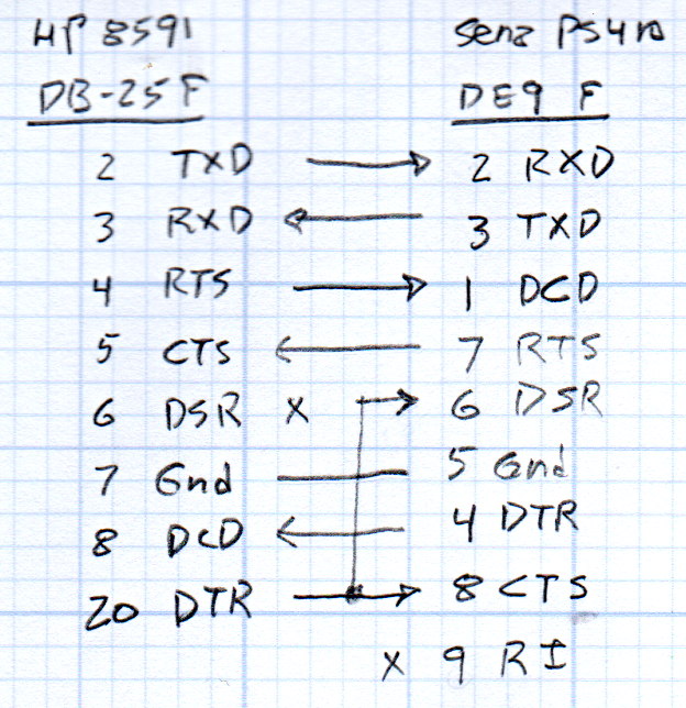
So I rewired the cable thusly:
HP 8591 vs Sena PS410 – RS232 cable diagram
Pin 1 on the 8591 interface connects to both frame ground and signal ground and, back when I first made this cable, many years ago, I had wired it to the shield of the cable and thence to the DE9 shell. Alas, the PS410 took offense; for reasons I don’t understand, a shell-to-ground connection ignites a ferrite bead on the PS410’s PCB.
With the rewired cable in hand, the PS410 serial port setup looks like this:
Port 2 – 8591 serial config
The PS410 apparently wiggles its RTS output after every byte it receives, because the CTS input at the 8591 turns into a blur during screen captures. This seems unaffected by the Inter character time-out setting and doesn’t (seem to) produce any problems, so it’s like that and that’s the way it is.
Using 9600 b/s isn’t as slow as you might think. The HP manual notes:
Some of the programs in this manual use 1200 baud for proper operation. If your system uses the RS-232 handshake lines, you can use 9600 baud for all of the programs.
I tried 19200 b/s and got mysterious errors that resemble overruns, which suggests the 8591 ignores the PS410’s flickering RTS output. The screen dumps require only a few seconds, so it’s not a big deal, although timing issues have a way of resurfacing at the most inopportune, uh, times.
Kermit knows how to handle network sockets and suchlike, so aiming it at the spectrum analyzer is a one-liner:
set host 192.168.1.40 7002 /raw-socket
set modem none
The /raw-socket disables Kermit’s default Telnet interface, preventing it from squirting IAC + BRK characters when closing the session; I think that’s what happens, but I don’t use Telnet enough to know better. As you might expect, the 8591 deals poorly with characters outside its lexicon.
It’s not obvious set modem none does anything in this context, but it seems reasonable.
Then the rest of the script Just Works:
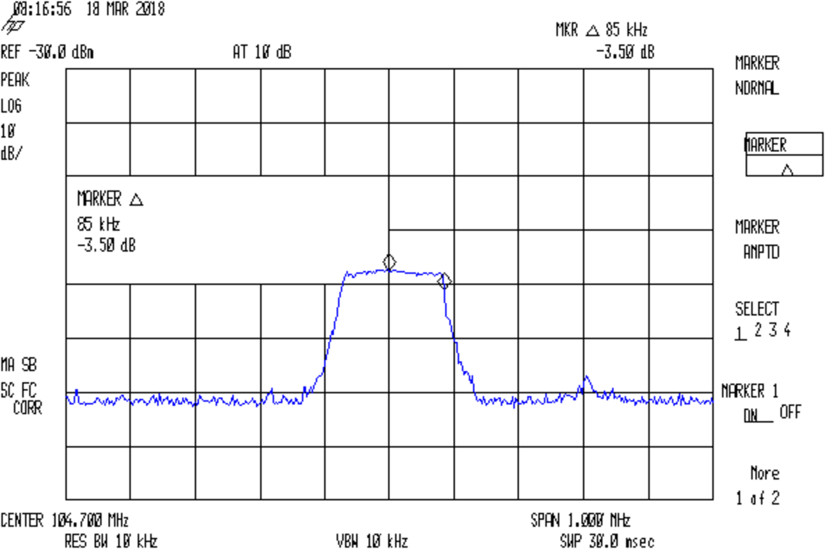
FM 104.7 MHz peak hold
Which is the peak-hold spectrum of a local FM station, as received through an amateur radio HT rubber duck antenna.
This file contains hidden or bidirectional Unicode text that may be interpreted or compiled differently than what appears below. To review, open the file in an editor that reveals hidden Unicode characters.
Learn more about bidirectional Unicode characters