Ed Nisley's Blog: Shop notes, electronics, firmware, machinery, 3D printing, laser cuttery, and curiosities. Contents: 100% human thinking, 0% AI slop.
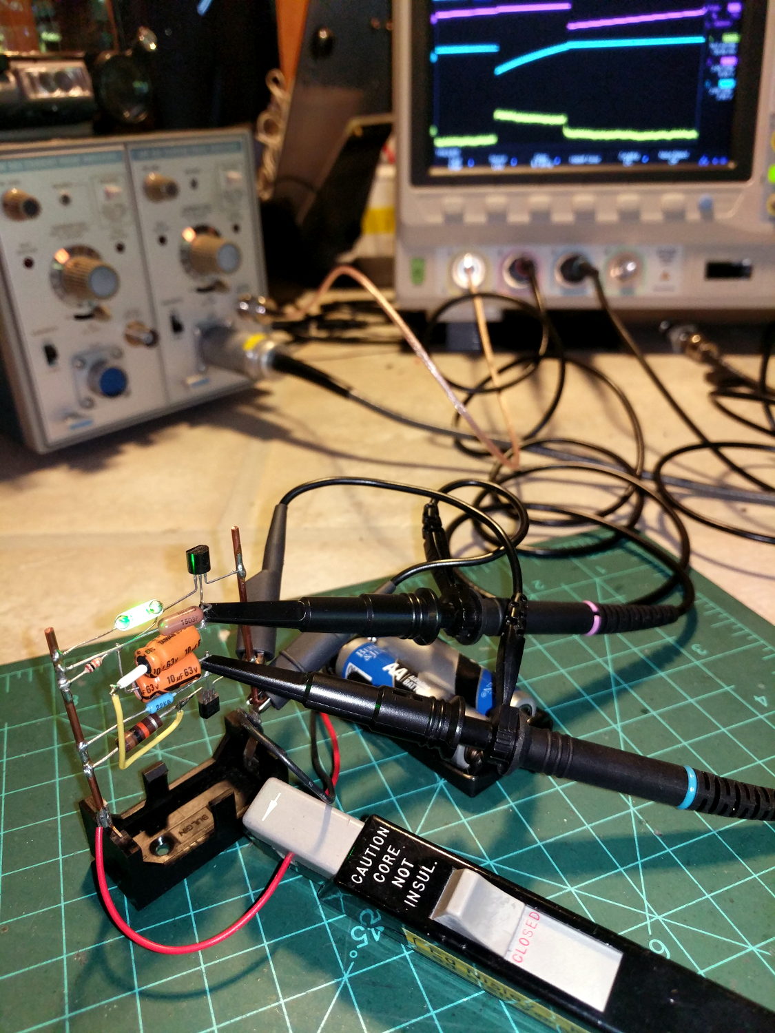
The question occasionally comes up as to why one would want a Tektronix A6302 Hall effect current probe and AM503 amplifier. The answer is simple: non-contact, essentially non-invasive current monitoring.
The scope screen in the background shows the two base voltages at the top, plus the overall battery current along the bottom:
Tek A6302 – Astable multivibrator – LED current 1 mA-div
The current at 1 mA/div shows plenty of noise, but the 200 ms LED pulse is barely 1 mA tall. The two AA alkaline cells have faded to 2.5 V, so the “wearable” white-LED-with-dyed-overcoat runs far under its nominal 3.6-ish V spec.
There’s basically no other way to get that result, because inserting a current-sense resistor into the circuit will alter the results, plus be intractably difficult to measure, particularly if you need the current in a non-ground-referenced branch of the circuit.
The AM503 has terrible thermal drift, by contemporary standards, but after the first half-hour or so it’s manageable for short durations. I’m thinking of epoxying a small knob to the screwdriver-adjustable twiddlepot to simplify the baseline adjustment.
Alas, even non-working probes and amps have become eBay collectables. You could, of course, buy new.
A package deal of two Tektronix A6302 current probes arrived from eBay, with one probe having a small crack across its case (shown in the description and bought accordingly).
The other probe worked fine and was quite clean inside:
A6302 B055461 – major sections
The cracked one couldn’t be balanced, with the twiddlepot on the AM503 amp unable to bring the signal down to 0 V from a positive offset on any of the ranges.
The current transformer might have suffered some stress on the upper-left corner of the main part (in the probe body), but it doesn’t have any obvious damage:
A6302 B032444 – ball – current transformer in place
The small ball to the left of the transfomer lid provides the slide detent; it’s an ordinary 3/32 = 0.094 inch bearing. Which, as it happens, is a Good Thing, because there’s another one exactly like it somewhere in the litter under the Electronics Workbench.
Protip: follow the disassembly procedure in the instruction manual and do it over a towel or, at least, a shallow dish. You have been warned.
Extracting the transformer from the body revealed a numeric value I didn’t recognize at the time:
A6302 B032444 – current transformer
The top slide contacts looked awful, but they’re actually covered in semi-dried contact grease and cleaned up easily:
A6302 B032444 – slide contacts
Swapping the “bad” transformer into the P6302 probe I got a while ago showed it wouldn’t balance, either, but the offset was far off into negative voltages. Putting the “good” transformer into the “bad” probe produced a similar too-positive offset. Conclusion: the transformer was probably good and Something Else was wrong.
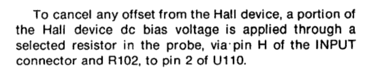
Spending more time with the manuals produced this hint in the AM503 Amplifier circuit description:
AM503 manual – Hall offset – probe resistor selection
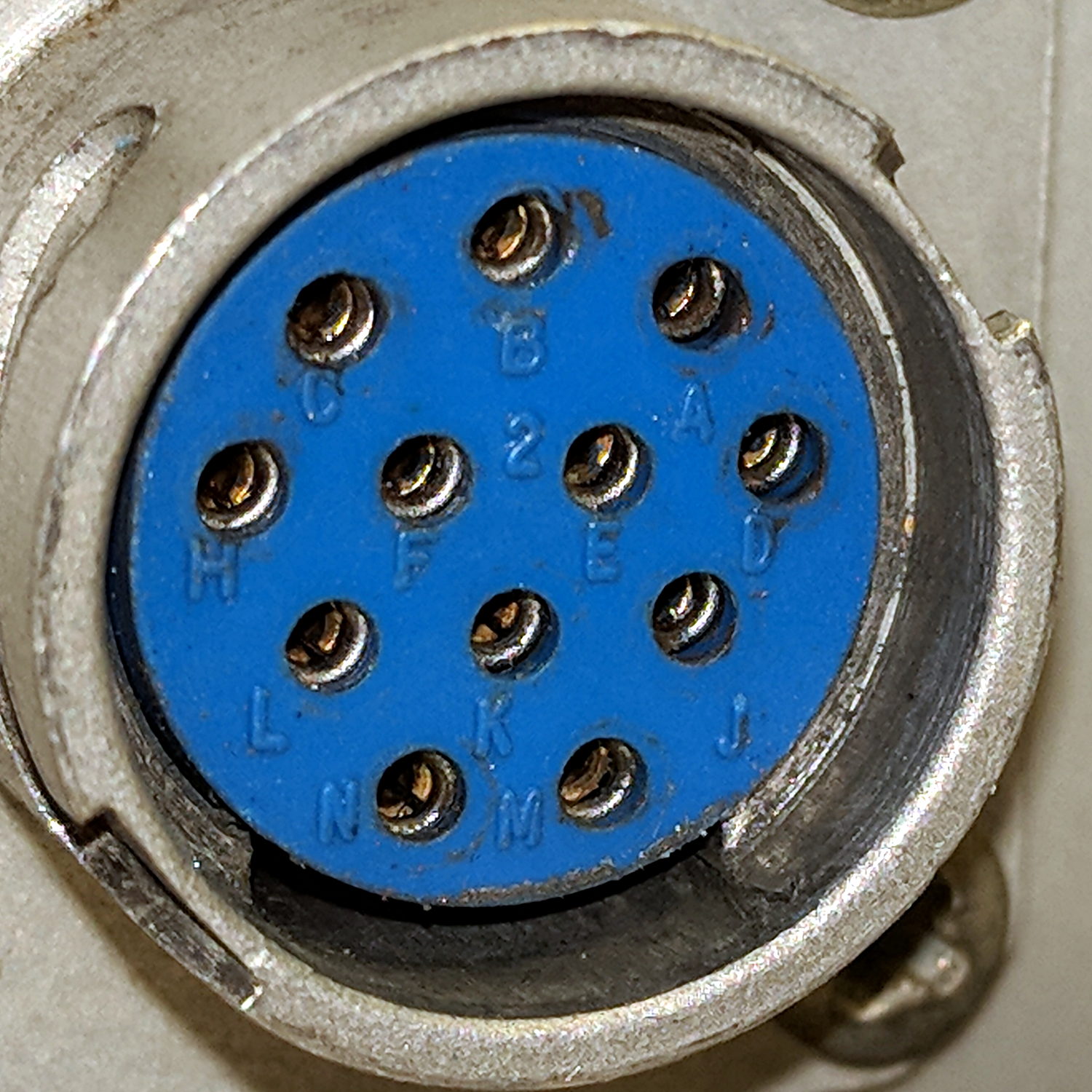
Fortunately, the AM503 probe connector has pin labels:
Tek AM503 Amplifier – Probe Connector – pin ID
Note the absence of pins G and I, probably to eliminate any confusion with “ground” and “one”, respectively.
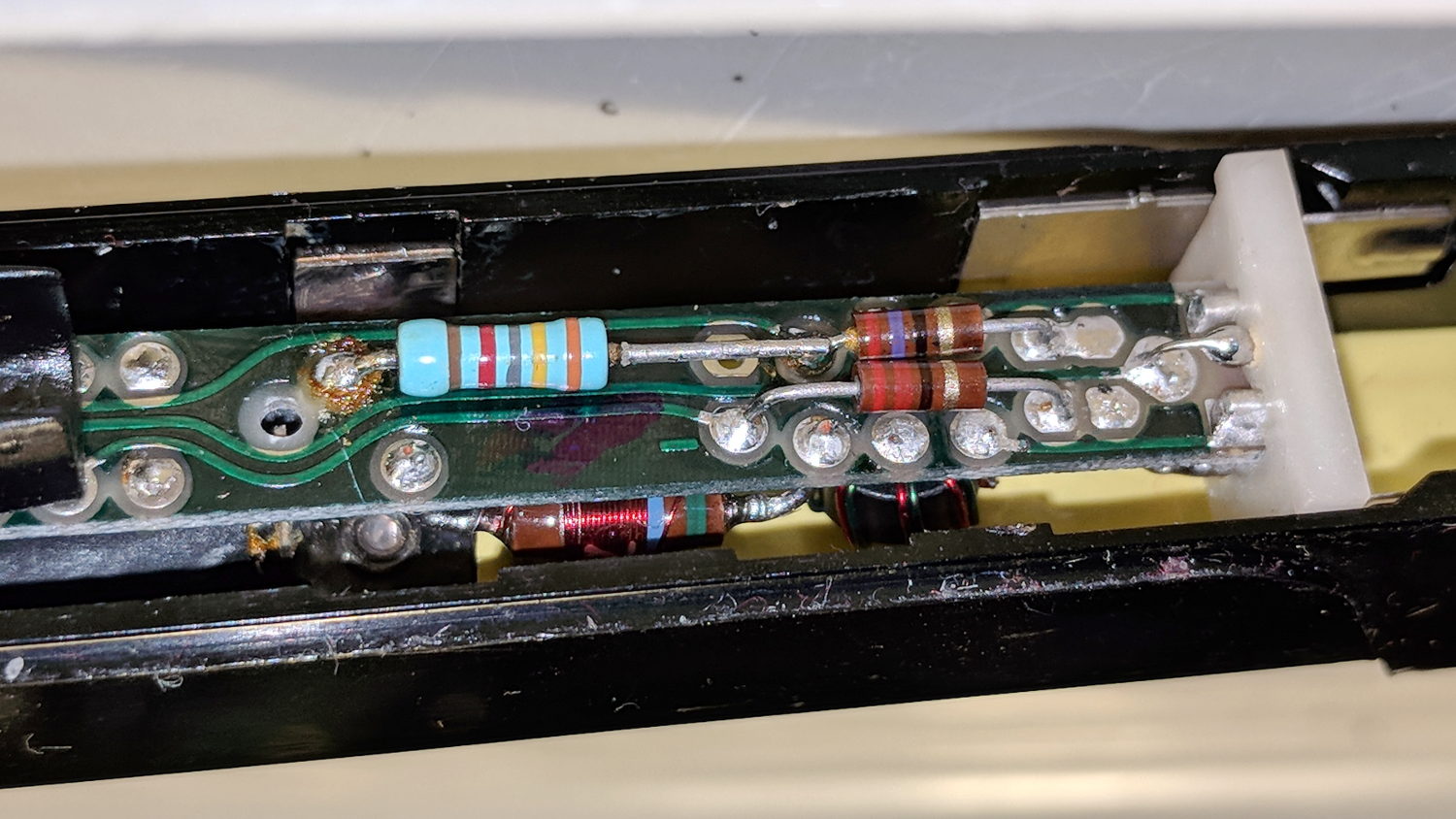
Continuity checking reveals the left end of the 34.8 kΩ resistor connects to pin H:
A6302 B032444 – PCB 34.8k offset R
Huh. Even a blind pig occasionally finds a truffle: where have we seen that value before? Apparently Tek measured each transformer / Hall sensor and wrote the appropriate offset resistor value exactly where it’d do the most good.
Although I don’t pretend to know why the transformer offset has changed, if Tek can select a resistor to correct the offset, so can I:
A6302 B032444 – PCB – tweaked 82k offset R
The 82 kΩ value roughly centers the offset twiddlepot span around 0 V; it’s the result of a binary search through the resistor drawers, rather than a complex calculation.
With the resistor in place and the probe reassembled in reverse order, everything works the way it should:
Tek A6302 – 82k ohm offset – 50 mA
The lower trace is a square wave from the scope’s arb waveform generator into a (likely counterfeit) Fotek DC-DC solid-state relay, with the bench supply dialed to 5.7 V to put 5 V across a hulking 100 Ω power resistor, thus 50 mA through the probe. The purple trace comes from the repaired probe, with the other one turned off for pedagogic purposes:
Tek A6302 Calibration Setup
That wasn’t easy, but seems to solve the problem.
Dang, I loves me some good Tek current probe action …
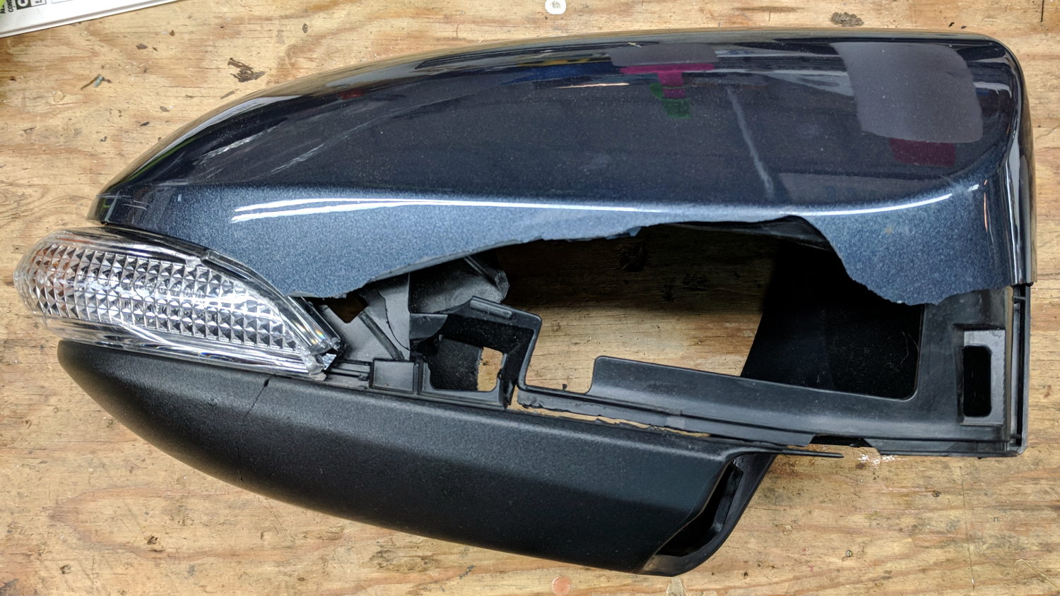
I hoped this bit of roadside debris would yield a shiny new amber LED and driver:
Car mirror – shattered housing
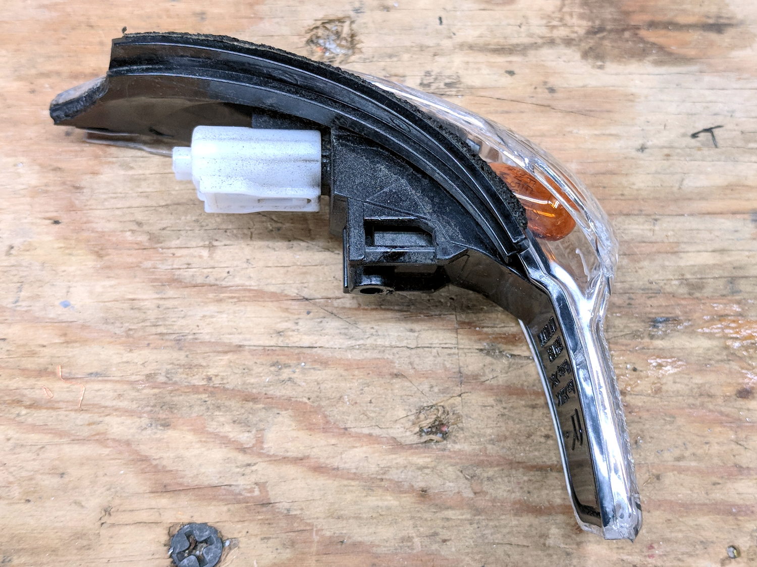
But, alas, it uses an ordinary WY5W incandescent bulb:
Car mirror – turn signal
That whole assembly seems to be the replaceable unit, as the lens is firmly snapped-and-glued to the housing. The white shell used to hold the wires, but those vanished when the collision ripped the mirror off the car.
After I pried off the shattered lens and extracted the bulb, I found a broken filament.
Ah, well, now we won’t be riding through plastic shards along the shoulder.
Both my Tek 2215A and HP 54602 oscilloscopes came with snap-on front covers to protect all those delicate knobs and connectors. Not so the Siglent SDS2304X, which is basically a flat shoebox with a handle: the case has no features for a cover to snap onto, Siglent doesn’t offer a padded carrying case, and it’s too thick big for any of the laptop bags around here.
I’ve been lugging it to Squidwrench meetings and can easily visualize a gash across the LCD panel or a knob rammed against a door frame.
So I trimmed a pair of foam angles, punched holes to fit around the knobs along the right edge, cut up a cardboard tray from the heap, and duct-taped the whole mess together:
Siglent SDS2304X Oscilloscope – crude front cover – interior
The cover is equally ugly from the outside:
Siglent SDS2304X Oscilloscope – crude front cover – installed
A Velcro bellyband around the whole affair / through the handle holds it together.
I considered 3D printing a set of corners and screwing them to a flat plastic plate, but came to my senses just in time.
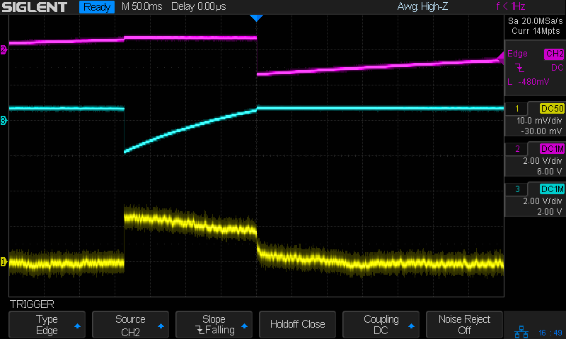
The ESP8266 controller in Sophi’s blimp project suffered from random resets, which I was absolutely certain happened when the current for the three DC prop motors glitched the battery supply. So I hauled the Tek current probes + amps + scope to a Squidwrench meeting and, after considerable fiddling, we found a smoking … trace:
Regulator dropout
The purple trace shows the Li-Ion battery voltage at an inactive motor driver located on the far end of a known-to-be-too-small trace. In principle, there’s little-to-no current drawn through that trace, so it should represent the voltage at the regulator input.
The green trace shows the 3.3 V regulator output at its bulk storage cap.
The ground reference is at the PCB’s battery negative connection pad.
The bold dotted green cursor shows the regulator output hitting 2.57 V, entirely low enough to glitch the ESP. The scope triggers on negative-going edges below 2.6 V and this was the first trigger after starting and running the motors for a few seconds.
Conspicuous by its absence: any hint of a current glitch in the yellow trace from a Tek A6302 probe clamped around the battery positive wire. The current remains constant at the 400 mA (100 mA/div) level drawn by two DC motors, with no sign of any glitches whatsoever; she’s not using PWM speed control. The whole board draws about 80 mA DC and the ESP’s WiFi radio pulls 200 mA pulses, so all’s quiet on those fronts.
Which is why I like to measure actual circuit operation: I vastly prefer to solve actual problems, knowing what does (or doesn’t!) cause them helps, and I’m not at all bothered by being wrong.
The regulator output doesn’t go much above 3.3 V, which is comforting.
However, when the regulator’s input voltage falls below 3.3-ish V, its output voltage tracks right along down with it. Input variations above 3.3-ish V don’t make much difference in the output.
Although it’s a buck-boost converter, its response time isn’t fast enough to cope with something else on the PCB pulling enough current to spike its input voltage (shared with the motor driver) below 3.3 V. The dropout is barely 4 ns long, far shorter than the regulator’s switching period.
I have my doubts as to the accuracy of those voltage waveforms and, in particular, their pulse widths. IIRC, the scope can trigger on a pulse exceeding a specific width, but I’d devote more time arranging the test points and getting RF-quality connections / grounding before going further out on a numeric limb.
This single trigger event may not be the glitch causing the reset. What it does show is the regulator output dropping below the ESP’s absolute-minimum input voltage spec, at least briefly, which is cause for concern.
Ex post facto notes from the third Squidwrench Electronics Workshop.
Exhibit various 50 Ω resistors, including my all-time favorite, a 600 W 3 GHz dummy load:
600 W Dummy Load Resistor
… down to a 1/8 Ω metal film resistor.
The dummy load’s N connector triggered a regrettable digression into RF, belatedly squelched because I wasn’t prepared to extemporize on AC concepts like reactance which we haven’t covered yet.
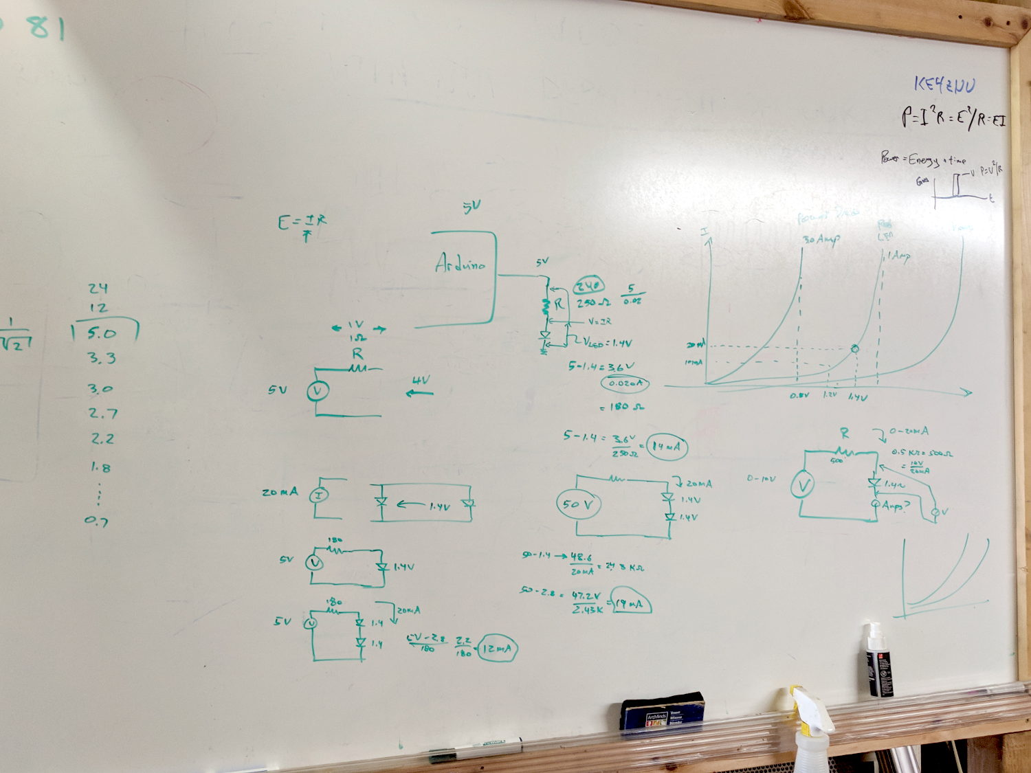
Discussion of resistor applications, power handling, power derating with temperature, etc:
Whiteboard – Session 3 – Resistor power derating
Why you generally won’t find 50 Ω load resistors in Raspberry Pi circuits. Cartridge heaters for 3D printers, not aluminum power resistors, although everyone agrees they look great:
Power resistors on heat spreader
Discussion of voltage vs. current sources, why voltage sources want low internal resistances and current sources want high resistances. Bungled discussion of current sources by putting diodes in parallel; they should go in series to show how added voltage doesn’t change current (much!) in sources driven from higher voltages through higher resistances:
Whiteboard – Session 3 – Voltage vs Current Sources
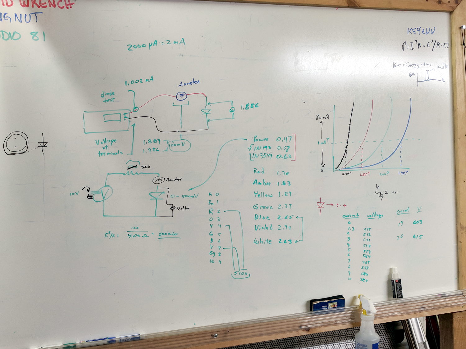
Use Siglent SDM3045X DMM in diode test mode to measure forward drop of power / signal / colored LEDs, discuss voltage variation with color / photon energy. Measure 1.000 mA test current for all forward voltages.
Compute series resistor (500 Ω) to convert adjustable power supply (the digital tattoo box, a lesson in itself) into reasonable current source; roughly 10 V → 20 mA. Find suitable resistor (560 Ω) in SqWr junk box parts assortment, digression into color band reading.
Wire circuit with meters to measure diode current (series!) and voltage (parallel!), measure same hulking power diode (after discovering insulating washers now in full effect) as before in 1 mA steps to 10 mA, then 15 and 20 mA, tabulate & plot results:
Whiteboard – Session 3 – Diode current vs forward drop
Discover warm resistor, compute power at 20 mA, introduce cautionary tales.
Lesson learned about never returning parts to inventory, with 560 Ω resistor appearing in diode drawer. Cautionary tales about having benchtop can of used parts as front-end cache for inventory backing store.
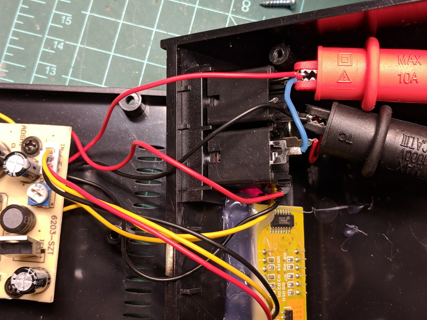
When I rewired the guts of the digital tattoo power supply to eliminate the series foot switch, I kept the original wiring polarity, with the black wire to the sleeve and the red wire to the tip:
Tattoo Digital Power Supply – internal view
It’s the same color code I (strongly) recommend in the Squidwrench Electronics Workshops: use any color for the ground / common wire as long as it’s black, then, if you have a red wire, use it for the positive supply. You can use yellow for the higher supply voltage, but stop being clever.
I put suitably colored Powerpoles on the far end of the cable to replace the standard tattoo machine spring clip connector, so I can attach clip leads, battery test fixtures, and so forth and so on.
We wired the supply into a clip-leaded diode measurement setup with a current limiting resistor and a pair of multimeters to measure the diode current and forward voltage, whereupon we noticed all the meters displayed negative voltages and currents.
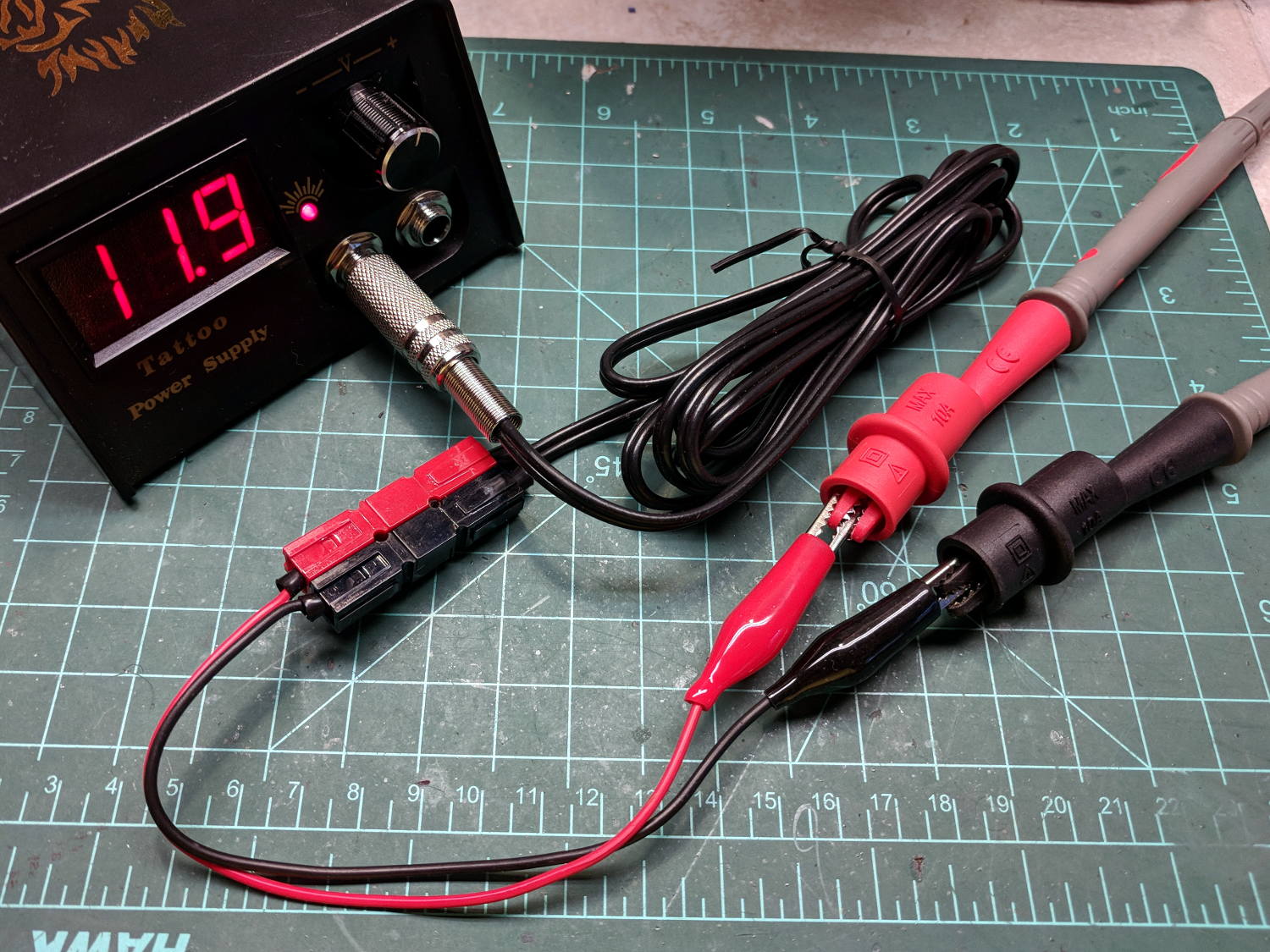
After a frenzy of wire-checking verified their setup was all good, I forced the simplest possible test, herein recreated on my bench:
Tattoo Digital Power Supply – polarity test
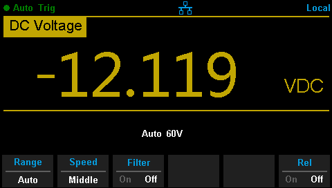
Which produced this display:
Tattoo Digital Supply – reverse polarity
Huh.
After a brief exploration of “Trust, but verify” territory, we swapped the clip leads from the power supply and continued the mission.
Back on my bench, I pulled the supply apart and measured the voltage at the jack terminals:
Tattoo Digital Power Supply – jack wiring
Still negative. Huh.
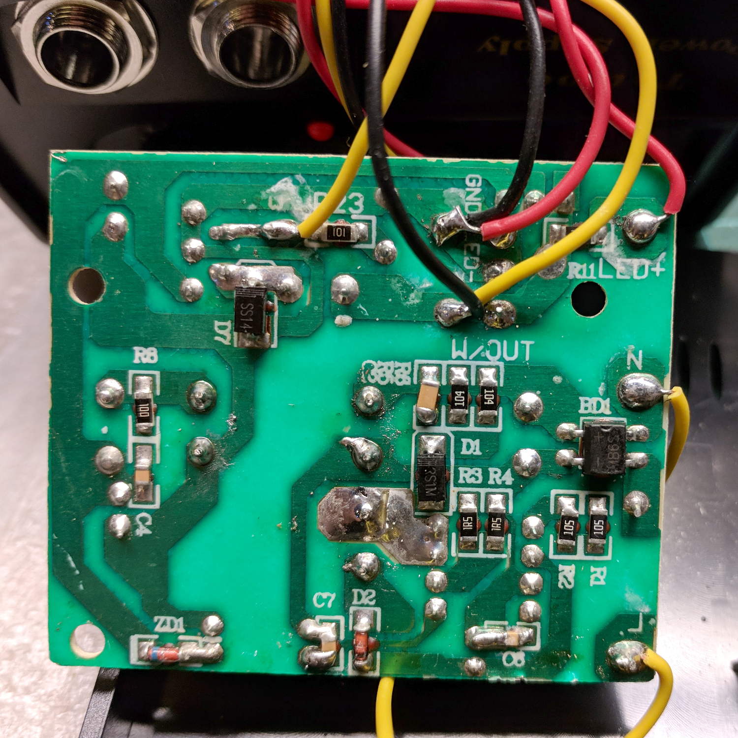
The bottom of the power supply PCB shows exactly what you should expect by now:
Tattoo Digital Power Supply – reversed color code
The red wire near the top of the board is, indeed, soldered to the trace labeled GND and goes to the jack’s tip terminal; the adjacent black wire goes to the front-panel LED. Similarly, the black wire just below it, soldered to the same trace as the yellow wire, goes to the jack’s sleeve terminal; that trace also connects to a resistor leading to the trace labeled LED+ and the LED’s red wire.
Although tattoo machines run from DC supplies, their motors or vibrators don’t depend on any particular polarity and will run fine with a backwards supply.
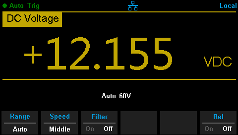
Resoldering the red and black wires where they should go produces the expected sign at the jack:
Tattoo Digital Supply – meter leads
Although measuring and plotting diode voltages and currents may seem tedious, actually wiring stuff together and taking data reveals how difficult the real world can be.
I trusted the supply’s internal color code and, although I’m certain I tested the Powerpoles, I obviously didn’t notice the meter’s sign.