Ed Nisley's Blog: Shop notes, electronics, firmware, machinery, 3D printing, laser cuttery, and curiosities. Contents: 100% human thinking, 0% AI slop.
Tek CC – Milled PETG cursor – Lacquer-Stik hairline
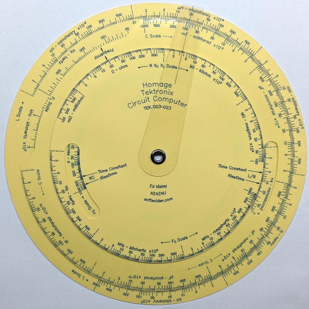
This time, I had the clear film on top!
Although the picture doesn’t do it justice, the scales are in blue ink, which looks better against the yellow background. I suppose I could do custom colors:
Pilot V5RT cartridge – ink levels
The line width has decreased as the ink level drops: 0.3 mm on yellow card stock and 0.2 mm on glossy white brochure paper. I don’t know if they’re supposed to work like that, but, for this application, narrower lines are definitely better.
The orange curve is the last surviving (“least dead”) Wasabi battery from the 2017-08 batch and the dark green curve just above it is another DOT-01 from 2019-02. The problem is not so much their reduced capacity, but their grossly reduced voltage-under-load that triggers a premature camera shutdown.
The Batmax batteries measure better than the craptastic Wasabi batteries, worse than the STK batteries, and should survive the next year of riding. As before, I have zero belief that Amazon would send me a “genuine” Sony NP-BX1 battery, even at six times the nominal price, nor that it would perform six times better.
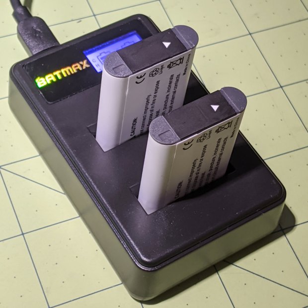
Batmax is one of many randomly named Amazon Marketplace sellers offering seemingly identical NP-BX1 batteries: Newmowa, Miady, Powerextra, Pickle Power, LP, Enegon, and so forth. Mysteriously, it’s always cheaper to get a handful of batteries and a charger, rather than just the batteries, so I now have a two-socket USB charger:
Batmax NP-BX1 – USB dual charger
Despite the “5 V 2 A – 10 W” and “4.2 V 0.6 A – 5 W” label on the back, charging a pair of batteries after a ride started at 700 mA from a USB 3.0 port. The charger makes no claims about USB 3 compliance, so I’d expect it to top out around 1 A from a generously specified port.
Eight minutes later, we’re turning onto the Dutchess County Rail Trail:
Losing the Battery Bag – flight – 2019-02-25
And then it’s gone:
Losing the Battery Bag – gone – 2019-02-25
Mary drove past there on her way to a distant meeting, but the little red bag was not to be found anywhere. Maybe it’ll reappear on a fence post or taped to the bulletin board; I’ve tried to return things I’ve found that way.
I expect somebody got a nice present and, if naught else, it’s good to drop happiness into the world.
There’s another reader and a quartet of batteries on their way.
Our CVS blood pressure meter (a relabeled Microlife unit) ran its pump for a few seconds this morning, gave up, and spat out Err 3, which translates into “Inflation of the cuff takes too long”. Not surprising, as the motor wasn’t running.
The AA alkaline cell quartet has plenty of mojo and no corrosion, but the motor doesn’t even turn over. The display is fine and the pressure release valve clicks, so it’s not completely dead.
This unit is sufficiently old to have the compelling advantage of transferring data through a USB (mini-B) connection, rather than a Bluetooth link through some sketchy Internet cloudy Android app, so it’s worth at least a look inside. Four screws and some internal snaps along the sides hold the case together; it’s a surprisingly easy teardown.
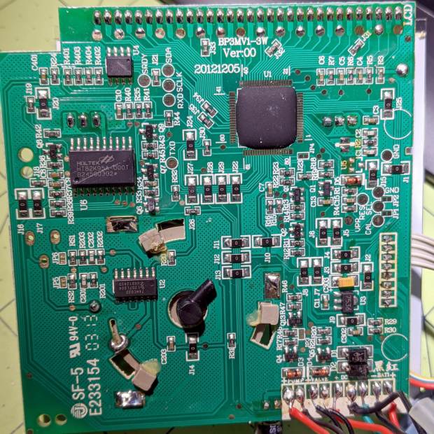
The business side of the PCB looks good:
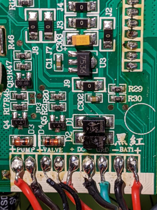
CVS Blood Pressure Monitor – PCB
The various wires and solder joints for the “high current” parts look OK, although the wires likely don’t go all the way through the PCB:
CVS Blood Pressure Monitor – PCB detail
Q4 and Q5 look like they switch the compressor pump motor and pressure-release valve. D3 and D4 should tamp down the inductive energy, but they look like they’re in series with the outputs. Yes, the Valve wires are both black.
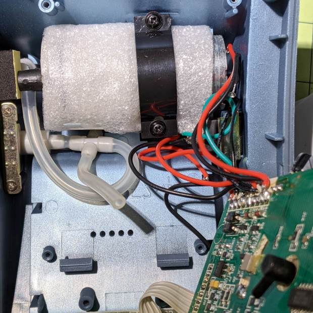
The motor has a foam vibration isolation wrap, which is a nice touch. Although you can’t see them well, all its wires & solder joints look like they’re in good shape:
CVS Blood Pressure Monitor – pump
The hose sticking out toward you plugs into the black right-angle fitting in the lower right corner of the picture. It’d help to have smaller fingers than mine, but I managed to get the hose off and on the fitting with only minor muttering.
Seeing nothing obviously wrong, I installed the same batteries, poked the switch to start a measurement, and the motor ran fine. Of course, the measurement failed because the cuff & pressure sensor weren’t connected.
Connect the hose, plug in the cuff & wrap it around my arm, poke the button, and everything works fine.
Reassemble everything and it still works fine.
I still think there’s a bad wire or solder joint in there somewhere, so this delightful “repair” can’t possibly last very long …
Mitchell 8.6 – Longitude computations of occultations 1872-1875
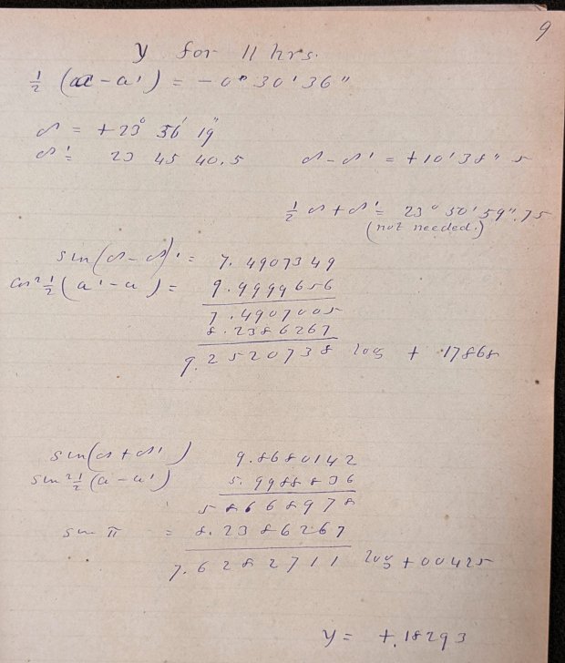
Here’s what “calculations” looked like in 1872:
Mitchell 8.6 p9 – Occultation of 1253 BAC at 11 hrs – calculation
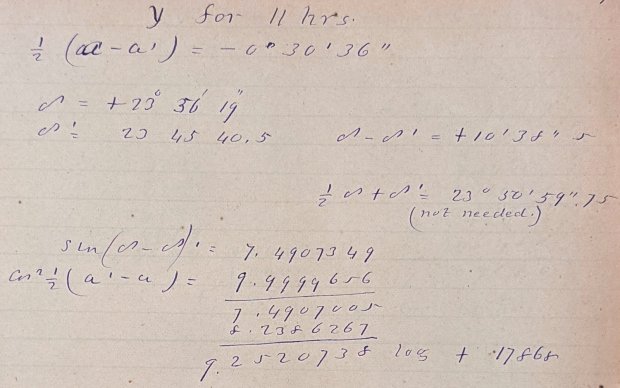
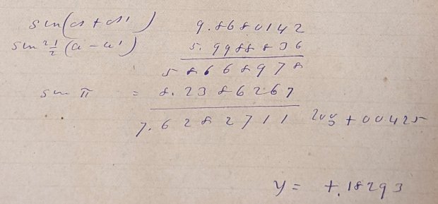
Yeah, grinding out trigonometry by hand using seven-place logarithms:
Mitchell 8.6 p9 – Occultation of 1253 BAC at 11 hrs – calculation detail 1
Not just by hand, but by hand with pen and ink:
Mitchell 8.6 p9 – Occultation of 1253 BAC at 11 hrs – calculation detail 2
Although you’ll find an occasional ink blot, she was probably using a fountain pen, rather than a dip pen, and made very few mistakes along the way. She often recorded direct instrument observations in pencil.
The next time you start pissing & moaning about how hard solid modeling is, suck it up.
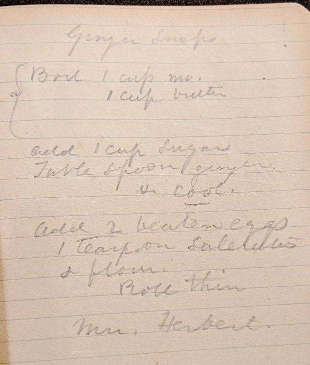
Bonus: a Ginger Snap recipe suggesting it wasn’t all toil & trouble in the observatory:
Mitchell 7.5 – Ginger Snap recipe
The mystery ingredient is saleratus, “aerated salt”, now known as baking soda; they used potassium bicarbonate before today’s sodium bicarbonate.
The quadrature detector, the black block on the left, is oriented with its lens (and, thus, the actual detectors) pointed away from the IR emitter. I thought it might be an assembly screwup, but it’s actually worse: the PCB layout is wrong.
A note from Tristan in NZ explains the situation:
So I have a later model than yours. It has a 2nd PCB chunk between where the legs normally would be. Just a floating piece with two holes for the legs, holding the legs from the board […] to the main board.It is also pointing the correct way (with the lens towards the three leg emitter).
Kensington scroll wheel revision2
The new quad detector has only three pins and no convex lens, but the active area now faces the emitter across the gap.
Because the interposer PCB occupies the space previously devoted to the emitter & detector leads, Kensington apparently soldered the new parts directly to the top surface without any clearance:
It’s like they failed to put through-vias to the rear or didn’t route them to the bottom another way, hence the solder is under the component
Tristan managed to wreck the detector while attempting to re-solder the intermittent joints, a situation I’m painfully familiar with. He replaced it with a quad detector harvested from a mid-90s optical mouse and it’s back in operation.
So I think the correct “fix” for the old-style PCBs (without the new interposer) is to unsolder the detector, rotate it so the lens faces the emitter, then somehow rewire the pins to the original pads. This won’t be easy and definitely won’t be pretty, but as long as it’s pointed in the right general direction it should work:
mine works off axis quite a bit
Should either of my Expert Mouse trackballs fail, now I know what to do
Many thanks to Tristan for reporting his findings!