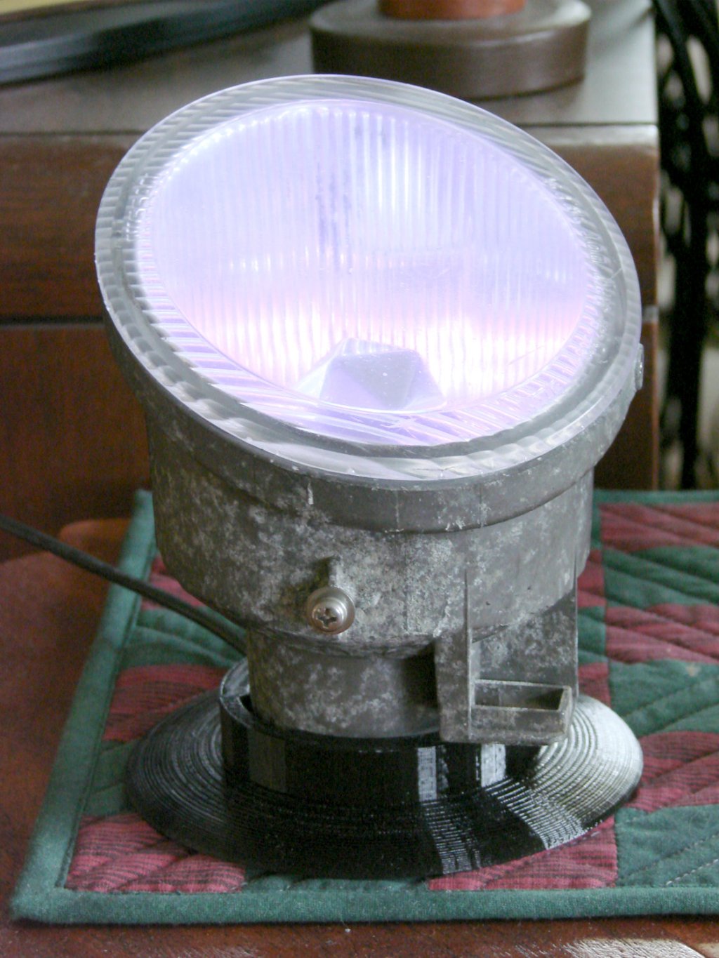
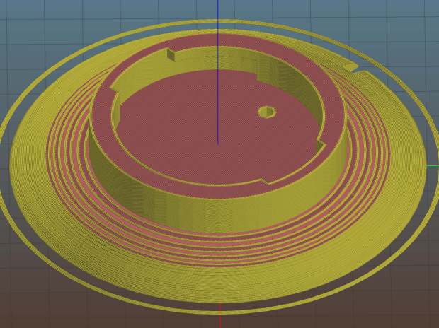
The upcycled Nissan fog lamp now has a desk stand:

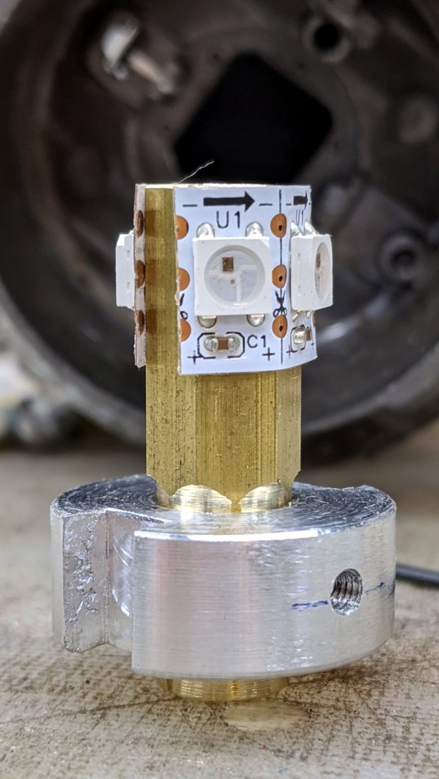
A knockoff Arduino Pro Mini atop a strip of foam tape drives the WS2812 RGB LEDs:
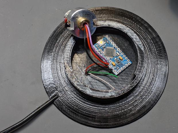
Next time, I’ll cut the wires another inch longer.
The firmware is a tidied-up version of the vacuum tube code, minus cruft, plus fixes, and generally better at doing what it does. The Pro Mini lacks a USB output, so this came from the same code running on a Nano:
14:44:04.169 -> Algorithmic Art
14:44:04.169 ->  RGB WS2812
14:44:04.169 -> Ed Nisley - KE4ZNU - April 2020
14:44:04.169 -> Lamp test: flash full-on colors
14:44:04.169 ->  color: 00ff0000
14:44:05.165 ->  color: 0000ff00
14:44:06.160 ->  color: 000000ff
14:44:07.155 ->  color: 00ffffff
14:44:08.151 ->  color: 00000000
14:44:09.180 -> Random seed: da98f7f6
14:44:09.180 -> Primes: 7 19 3
14:44:09.180 ->  Super cycle length: 199500 steps
14:44:09.180 -> Inter-pixel phase: 1 deg = 26 steps
14:44:09.180 ->  c: 0 Steps:  3500 Init:  1538 Phase:   2 deg PWM: 255
14:44:09.180 ->  c: 1 Steps:  9500 Init:  7623 Phase:   0 deg PWM: 255
14:44:09.213 ->  c: 2 Steps:  1500 Init:  1299 Phase:   6 deg PWM: 255
14:44:19.265 -> Color 2     steps 1500  at 15101    ms 50       TS 201
14:45:34.293 -> Color 2     steps 1500  at 90136    ms 50       TS 1701
14:45:43.085 -> Color 1     steps 9500  at 98940    ms 50       TS 1877
14:45:47.332 -> Color 0     steps 3500  at 103192   ms 50       TS 1962
14:46:49.324 -> Color 2     steps 1500  at 165170   ms 50       TS 3201
… much snippage …
17:26:52.896 -> Color 2     steps 1500  at 9769584  ms 50       TS 195201
17:28:07.926 -> Color 2     steps 1500  at 9844618  ms 50       TS 196701
17:29:11.000 -> Color 0     steps 3500  at 9907697  ms 50       TS 197962
17:29:22.974 -> Color 2     steps 1500  at 9919653  ms 50       TS 198201
17:30:27.941 -> Supercycle end, setting new color values
17:30:27.941 -> Primes: 17 7 3
17:30:27.941 ->  Super cycle length: 178500 steps
17:30:27.941 -> Inter-pixel phase: 1 deg = 23 steps
17:30:27.941 ->  c: 0 Steps:  8500 Init:  5415 Phase:   0 deg PWM: 255
17:30:27.974 ->  c: 1 Steps:  3500 Init:  3131 Phase:   2 deg PWM: 255
17:30:27.974 ->  c: 2 Steps:  1500 Init:   420 Phase:   5 deg PWM: 255
17:30:46.394 -> Color 1     steps 3500  at 10003091 ms 50       TS 369
17:31:21.964 -> Color 2     steps 1500  at 10038658 ms 50       TS 1080
The “Super cycle length” is the number of 50 ms steps until the colors start repeating, something over an hour in that sample. When the code reaches the end of the supercycle, it picks another set of three prime numbers, reinitializes the color settings, and away it goes.
The fog light looks pretty in action:

The four LEDs don’t produce the same light pattern as the halogen filament and they’re distinctly visible when you squint against the glare:

The shadow on the right comes from the larger hood support strut, the shadow on the left is the narrower strut, and the two other gaps show the beam angle gaps between the LEDs.
You’ll see plenty of residual sandpaper scratches on the lens: my surface (re)finishing hand is weak.
The LED beamwidth is so broad the “bulb” position inside the reflector doesn’t make much difference, particularly as it must, at most, wash a wall and ceiling at close range:

All in all, a much-needed dose of Quality Shop Time.
The Arduino source code as a GitHub Gist:
| // Neopixel Algorithmic Art | |
| // W2812 RGB Neopixel version | |
| // Ed Nisley – KE4ZNU | |
| #include <Adafruit_NeoPixel.h> | |
| #include <Entropy.h> | |
| //———- | |
| // Pin assignments | |
| const byte PIN_NEO = A3; // DO – data out to first Neopixel | |
| const byte PIN_HEARTBEAT = 13; // DO – Arduino LED | |
| #define PIN_MORSE 12 | |
| //———- | |
| // Constants | |
| // number of pixels | |
| #define PIXELS 4 | |
| // lag between adjacent pixels in degrees of slowest period | |
| #define PIXELPHASE 1 | |
| // update LEDs only this many ms apart (minus loop() overhead) | |
| #define UPDATEINTERVAL 50ul | |
| #define UPDATEMS (UPDATEINTERVAL – 0ul) | |
| // number of steps per cycle, before applying prime factors | |
| #define RESOLUTION 500 | |
| //———- | |
| // Globals | |
| Adafruit_NeoPixel strip = Adafruit_NeoPixel(PIXELS, PIN_NEO, NEO_GRB + NEO_KHZ800); | |
| uint32_t FullWhite = strip.Color(255,255,255); | |
| uint32_t FullOff = strip.Color(0,0,0); | |
| uint32_t MorseColor; | |
| struct pixcolor_t { | |
| unsigned int Prime; | |
| unsigned int NumSteps; | |
| unsigned int Step; | |
| float StepSize; | |
| float Phase; | |
| byte MaxPWM; | |
| }; | |
| unsigned long int TotalSteps; | |
| unsigned long int SuperCycleSteps; | |
| byte PrimeList[] = {3,5,7,11,13,17,19,29}; // small primes = faster changes | |
| // colors in each LED and their count | |
| enum pixcolors {RED, GREEN, BLUE, PIXELSIZE}; | |
| struct pixcolor_t Pixel[PIXELSIZE]; // all the data for each pixel color intensity | |
| uint32_t UniColor; | |
| unsigned long int MillisNow; | |
| unsigned long int MillisThen; | |
| //– Select three unique primes for the color generator function | |
| // Then compute all the step parameters based on those values | |
| void SetColorGenerators(void) { | |
| Pixel[RED].Prime = PrimeList[random(sizeof(PrimeList))]; | |
| do { | |
| Pixel[GREEN].Prime = PrimeList[random(sizeof(PrimeList))]; | |
| } while (Pixel[RED].Prime == Pixel[GREEN].Prime); | |
| do { | |
| Pixel[BLUE].Prime = PrimeList[random(sizeof(PrimeList))]; | |
| } while (Pixel[BLUE].Prime == Pixel[RED].Prime || | |
| Pixel[BLUE].Prime == Pixel[GREEN].Prime); | |
| if (false) { | |
| Pixel[RED].Prime = 1; | |
| Pixel[GREEN].Prime = 3; | |
| Pixel[BLUE].Prime = 5; | |
| } | |
| printf("Primes: %d %d %d\r\n",Pixel[RED].Prime,Pixel[GREEN].Prime,Pixel[BLUE].Prime); | |
| TotalSteps = 0; | |
| SuperCycleSteps = RESOLUTION; | |
| for (byte c = 0; c < PIXELSIZE; c++) { | |
| SuperCycleSteps *= Pixel[c].Prime; | |
| } | |
| printf(" Super cycle length: %lu steps\r\n",SuperCycleSteps); | |
| Pixel[RED].MaxPWM = 255; | |
| Pixel[GREEN].MaxPWM = 255; | |
| Pixel[BLUE].MaxPWM = 255; | |
| unsigned int PhaseSteps = (unsigned int) ((PIXELPHASE / 360.0) * | |
| RESOLUTION * (unsigned int) max(max(Pixel[RED].Prime,Pixel[GREEN].Prime),Pixel[BLUE].Prime)); | |
| printf("Inter-pixel phase: %d deg = %d steps\r\n",(int)PIXELPHASE,PhaseSteps); | |
| for (byte c = 0; c < PIXELSIZE; c++) { | |
| Pixel[c].NumSteps = RESOLUTION * Pixel[c].Prime; // steps per cycle | |
| Pixel[c].StepSize = TWO_PI / Pixel[c].NumSteps; // radians per step | |
| Pixel[c].Step = random(Pixel[c].NumSteps); // current step | |
| Pixel[c].Phase = PhaseSteps * Pixel[c].StepSize; // phase in radians for this color | |
| printf(" c: %d Steps: %5d Init: %5d Phase: %3d deg",c,Pixel[c].NumSteps,Pixel[c].Step,(int)(Pixel[c].Phase * 360.0 / TWO_PI)); | |
| printf(" PWM: %d\r\n",Pixel[c].MaxPWM); | |
| } | |
| } | |
| //– Helper routine for printf() | |
| int s_putc(char c, FILE *t) { | |
| Serial.write(c); | |
| } | |
| //—————— | |
| // Set the mood | |
| void setup() { | |
| pinMode(PIN_HEARTBEAT,OUTPUT); | |
| digitalWrite(PIN_HEARTBEAT,LOW); // show we arrived | |
| Serial.begin(57600); | |
| fdevopen(&s_putc,0); // set up serial output for printf() | |
| printf("Algorithmic Art\r\n RGB WS2812\r\nEd Nisley – KE4ZNU – April 2020\r\n"); | |
| Entropy.initialize(); // start up entropy collector | |
| // set up pixels | |
| strip.begin(); | |
| strip.show(); | |
| // lamp test: a brilliant white flash | |
| printf("Lamp test: flash full-on colors\r\n"); | |
| uint32_t FullRGB = strip.Color(255,255,255); | |
| uint32_t FullR = strip.Color(255,0,0); | |
| uint32_t FullG = strip.Color(0,255,0); | |
| uint32_t FullB = strip.Color(0,0,255); | |
| uint32_t FullOff = strip.Color(0,0,0); | |
| uint32_t TestColors[] = {FullR,FullG,FullB,FullRGB,FullOff}; | |
| for (byte i = 0; i < sizeof(TestColors)/sizeof(uint32_t) ; i++) { | |
| printf(" color: %08lx\r\n",TestColors[i]); | |
| for (int p=0; p < strip.numPixels(); p++) { | |
| strip.setPixelColor(p,TestColors[i]); | |
| } | |
| strip.show(); | |
| delay(1000); | |
| } | |
| // get an actual random number | |
| uint32_t rn = Entropy.random(); | |
| printf("Random seed: %08lx\r\n",rn); | |
| randomSeed(rn); | |
| // set up the color generators | |
| SetColorGenerators(); | |
| MillisNow = MillisThen = millis(); | |
| } | |
| //—————— | |
| // Run the mood | |
| void loop() { | |
| MillisNow = millis(); | |
| if ((MillisNow – MillisThen) >= UPDATEMS) { // time for another step? | |
| digitalWrite(PIN_HEARTBEAT,HIGH); | |
| TotalSteps++; | |
| strip.show(); // send out precomputed colors | |
| for (byte c = 0; c < PIXELSIZE; c++) { // compute next increment for each color | |
| if (++Pixel[c].Step >= Pixel[c].NumSteps) { | |
| Pixel[c].Step = 0; | |
| printf("Color %-5d steps %-5d at %-8ld ms %-8ld TS %-8lu\r\n", | |
| c,Pixel[c].NumSteps,MillisNow,(MillisNow – MillisThen),TotalSteps); | |
| } | |
| } | |
| // If all cycles have completed, reset the color generators | |
| if (TotalSteps >= SuperCycleSteps) { | |
| printf("Supercycle end, setting new color values\r\n"); | |
| SetColorGenerators(); | |
| } | |
| for (int p = 0; p < strip.numPixels(); p++) { // for each pixel | |
| byte Value[PIXELSIZE]; | |
| for (byte c=0; c < PIXELSIZE; c++) { // compute new colors | |
| Value[c] = (Pixel[c].MaxPWM / 2.0) * (1.0 + sin(Pixel[c].Step * Pixel[c].StepSize – p*Pixel[c].Phase)); | |
| } | |
| UniColor = strip.Color(Value[RED],Value[GREEN],Value[BLUE]); | |
| strip.setPixelColor(p,UniColor); | |
| } | |
| MillisThen = MillisNow; | |
| digitalWrite(PIN_HEARTBEAT,LOW); | |
| } | |
| } |