Ed Nisley's Blog: Shop notes, electronics, firmware, machinery, 3D printing, laser cuttery, and curiosities. Contents: 100% human thinking, 0% AI slop.
The CHDK firmware for Canon point-and-shoot cameras includes a USB remote trigger feature that depends on simply applying +5 V to the USB power leads, which is exactly what happens when you plug an ordinary USB cable into a PC.
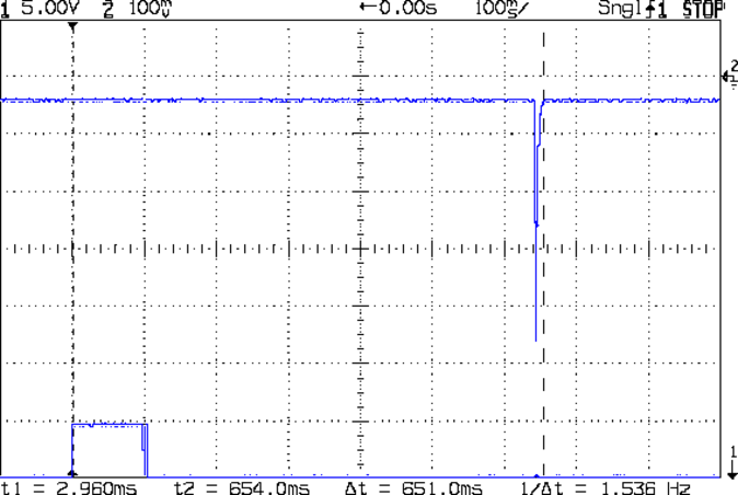
Chopping up a spare cable, adding header pins, attaching a bench supply, and whacking the pins with clip leads showed that the camera takes quite a while to haul itself to its feet and click the shutter:
Canon SX230HS – USB trigger – flash
That’s with:
Manual mode: preset shutter & aperture
Manual focus
Focus assist off
Image stabilization off
AF guide light off
Red eye reduction off
Flash enabled, medium intensity, precharged
Turning the flash off slightly reduces the delay, at least judging from when I hear the shutter click while watching the trace trundle across the screen. I may have forgotten to turn something else off, but I doubt it’ll get an order of magnitude faster.
I’d hoped to synchronize an outboard flash with the shutter, but watching a few traces shows that the time from trigger to flash isn’t very consistent; maybe 100 ms jitter, more or less.
The CHDK motion-sensing script works and is “lightning fast”, but it turns out that lightning strokes actually glow for tens to hundreds of milliseconds, so my 1 ms xenon flash will be over and done with by the time the script reacts and opens the camera shutter.
Other ways to synchronize an outboard flash with the shutter:
Fire the outboard flash from the camera flash, with the camera flash inside a shield
Use an absurdly long shutter time with the camera & objects inside a very, very dark enclosure
Use the CHDK motion detection script, but blink an LED into the lens to trigger the shutter, then fire the xenon flash to expose the image
Choice 1 has positive synchronization to the camera shutter, but the shutter delay jitter means the flash won’t happen after a fixed delay from the triggering event. Maybe it’s not as bad as I think.
Choice 2 requires that the shutter stay open longer than the maximum delay jitter, so the flash will happen at known time after the triggering event. I like that, but not the dark enclosure part.
Choice 3 depends on the timing jitter of the script, which should be on the order of a few tens of milliseconds. A shutter speed of 1/25 s = 40 ms might be Good Enough.
This obviously requires a bit of Arduino fiddling…
I’m thinking of taking strobe pictures again, but the results of the LED strobe tach experiment showed that I need many more LEDs, much brighter LEDs, or entirely different technology. The Big Box o’ Xenon Tubes disgorged some surplus camera flash units that seemed amenable to hackage.
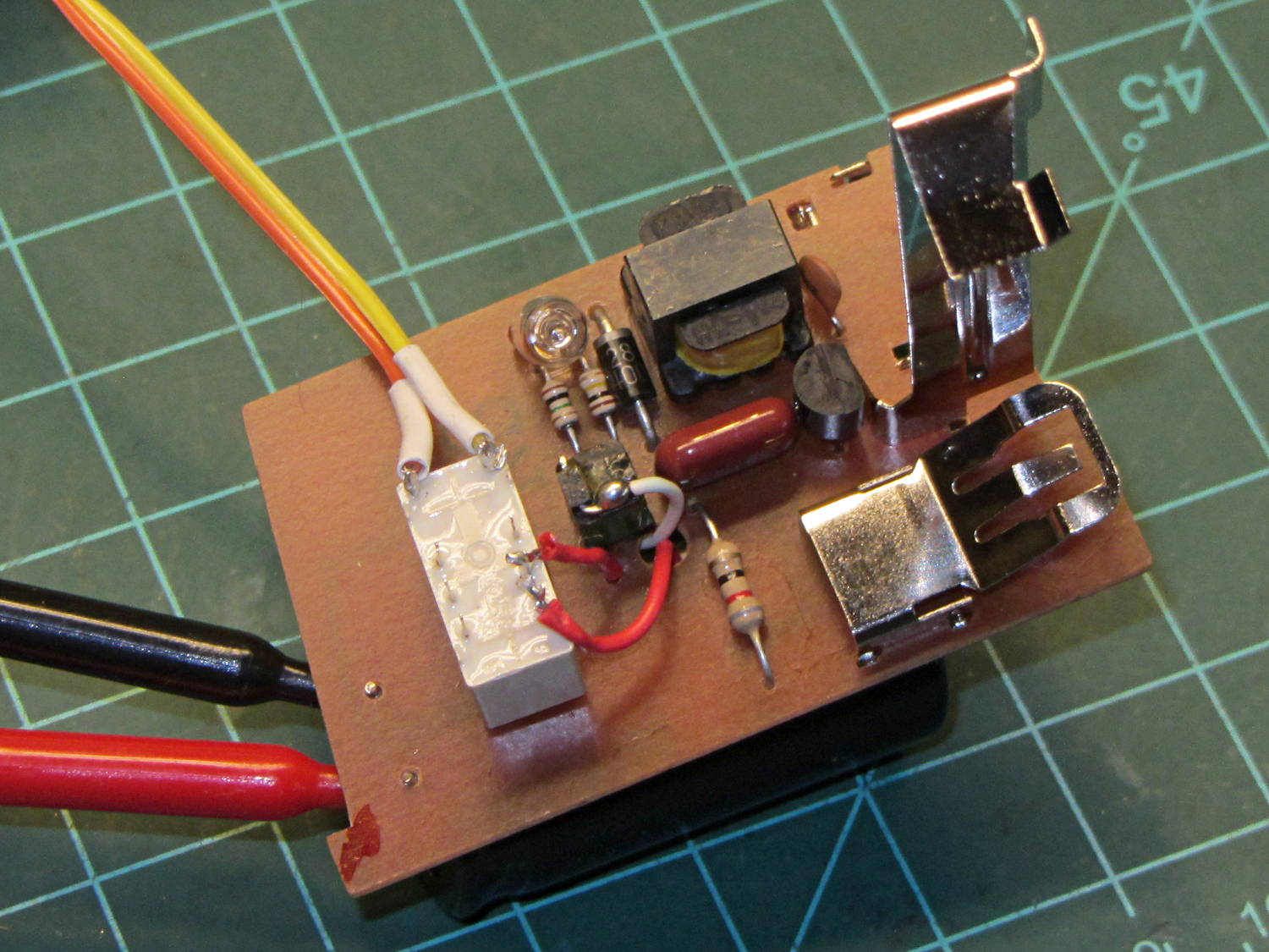
The canonical digital trigger uses an optocoupled triac, so I soldered a MOC3022, taken from a random assortment of various optocouplers, across the trigger leads:
Xenon flash – MOC3022 triac
Alas, that didn’t trigger the flash reliably. It may well be that the triac’s leakage current drains the small trigger capacitor below the voltage required to produce a suitable trigger pulse, but I was unwilling to poke around in the thing.
The clip leads go off to a DVM set to the 600 VDC range, which is, I think, the first time the range switch has ever lingered in that position. The 250 µF 330 V capacitor charges to about 300 V, depending on the mojo of the single AA cell powering it, and discharges to about 50 V after the arc quenches. The neon bulb lights when the capacitor goes above 280 V.
The reed relay assortment emitted an ancient Clare 1A05C relay with, as nearly as I could make out from the fragmentary datasheets available nowadays, barely adequate specs:
Xenon flash – PRME 1A05C relay
Unfortunately (and as I rather expected), the first shot welded the contacts together.
A somewhat larger Axicom (aka Tyco) V23079A1011B301 (I’m not making that up) relay had better specs: 220 VDC / 250 VAC / 2 A contacts. The DC rating isn’t relevant here, because the contacts will break only 50 V after the flash, and the AC rating says it’ll withstand well over 350 V.
As with the other gadgets, a blob of hot melt glue holds it in place:
Xenon flash – Axicom V23079 A1011-B301 relay
That worked wonderfully well:
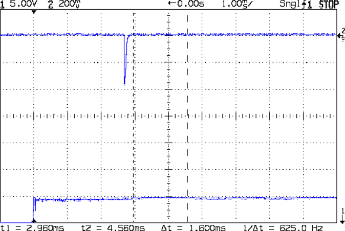
Xenon 280 V 250 uF
The upper trace comes from a PIN-10AP photodiode in the LED measurement fixture, minus the black cap holding the LED. The photodiode connects directly to the oscilloscope input, so we’re seeing its photovoltaic response rather than the photocurrent, but that’s good enough for now. The pulse is about 1.5 ms long at the 50% level (that’s 1 EV down from the peak) and the tail is pretty much gone by 3 ms.
The 3 ms delay after applying voltage to the coil (lower trace, showing what happens when you use a clip lead as a switch) is well within the 4 ms spec in the datasheet. The release time isn’t relevant, as the capacitor has discharged to 50 V and nothing exciting happens when the contacts open.
Charging the stock 250 µF cap to 280 V stores 10 J = 10 W·s:
10 J = (1/2) (250×10-6) (2802)
Discharged to 50 V, the cap has only 0.3 J left, so most of the energy goes into the arc.
Swapping a 1 µF 600 V film capacitor for the electrolytic cap narrows the pulse:
Xenon 350 V 1 uF
A 1 µF cap should reduce the stored energy by a factor of 250 to 0.4 J, but the booster charged it to 350 V = 0.6 J:
0.6 J = (1/2) (1×10⁻⁶) (3502)
The test setup, a term that barely applies in this situation, isn’t stable enough to say anything about the relative light output, but it’s certainly not an order of magnitude worse than the 10 J shot (some data and curves from an OEM). The pulse width is maybe 100 µs, just about what I used with the LEDs, but whether the lamp produces enough illumination remains to be seen; it should be brighter than the LEDs.
The boost circuit requires about ten seconds to recharge the 250 µF cap and maybe 250 ms for the 1 µF cap. The Axicom relay can operate at 50 Hz at no load, which definitely won’t constrain the flash rate. The trigger energy at the contacts should be about the same for either flash capacitor, because it comes from a much smaller capacitor charged to the same voltage; buzzing away at a high rep rate will chew up the contacts fairly quickly.
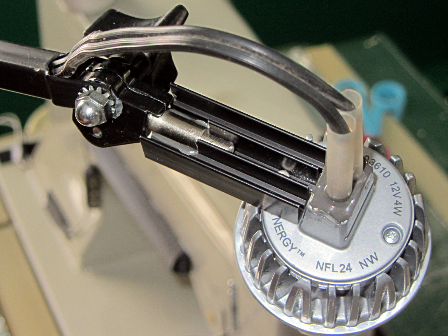
Quite a while ago, I rebuilt a gooseneck shop lamp with an LED floodlight module, the light from which appears in many pictures of the Sherline mill. That module has a sibling that I just combined with a defunct halogen desk lamp to produce a better task light for the bench; the original 12 VAC 50 W transformer now loafs along at 4 W and ballasts the lamp base against tipping.
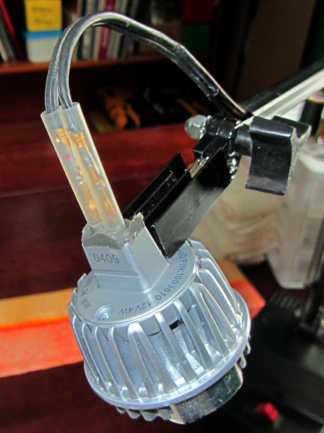
My initial idea, of course, was a 3D printed adapter from the existing arm hardware to the LED module, but PLA gets droopy at normal high-intensity LED heatsink temperatures. That led to doodling a metal bracket around the LED module flange, which led to pondering how annoying that would be to make, which led to the discovery that the screws holding the LED plug to the heatsink were ordinary M2x0.4 Philips head, which suggested I could just screw a bracket to the back of the module, which brought a recently harvested aluminum heatsink to hand, which led to the discovery that the tip of the pivot screw fit perfectly between the fins, which …
Shortly thereafter, I milled off the central fins to fit the shaft of the pivot screw, introduced the heatsink to Mr. Disk Sander to bevel the bottom, sawed the threads off the pivot, press-fit the two together, drilled a 2 mm cross-hole into the pivot, buttered it all up with epoxy, jammed a short M2 screw into the cross hole, and let the whole mess cure:
Desk Lamp LED Adapter – top view
The lamp modules were a surplus find, with one pin clipped nearly flush to the insulator. I soldered a pair of the same male pins as in the battery holders, with the matching female pins as a crude connector. The unshrunk heatstink tubing isn’t lovely, but got us to First Light:
Desk Lamp LED Adapter – front view
The original counterweight is, of course, much too heavy for the dinky LED module, so I’ll drill the mounting hole for the vertical arm further back on the beam to get another foot of reach. That will require more wire between the transformer to the lamp, soooo the connectors might just become soldered joints.
As you can tell from the background, Mary snatched the lamp from my hands and put it to immediate use in The Quilting Room.
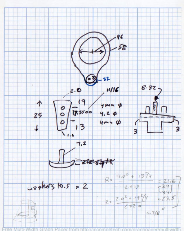
The original doodles bear no resemblance to the final product, but do have some key dimensions that (having discarded the unused hardware) I’ll likely never need again.
The pivot between the arm and the lamp housing, with an idea for the LED holder:
Desk Lamp Bracket Dimensions – doodle
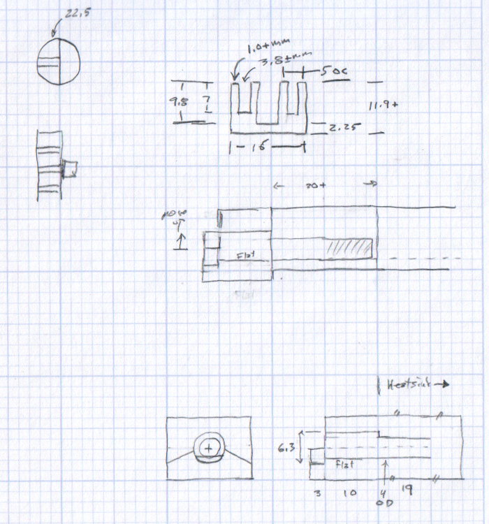
Details of the repurposed heatsink and the pivot bolt, with a block that never got built:
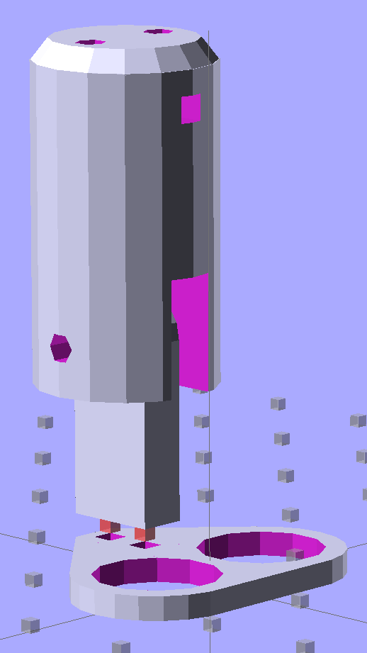
Some trial fitting with the prototype showed that there’s no possible way to route the connections through the socket, no matter how much I wanted that to happen, so I rotated the body to align the LEDs with the socket pin slots:
Sears Lamp LED Adapter – Show view
The body now builds with the flat end down, so the overall finish should be better:
Sears Lamp LED Adapter – Build view
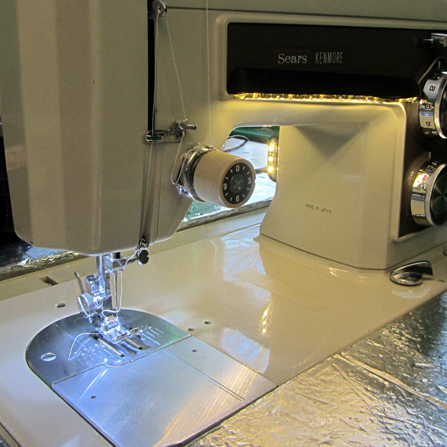
A test run shows why I really, really wanted cool white LEDs in the strips over the arm:
Kenmore 158 Sewing Machine – mixed LED lighting
The LED mount doesn’t have quite enough room inside the end cap for the holder to tilt as I wanted; the two 10 mm LEDs can be about 10 mm lower and slightly closer to the shaft driving the needle, which is what this rapid prototyping stuff is all about. Scrapping the existing lamp socket and (120 VAC!) wiring seems the best way to make this more useful.
Early reports on the arm LEDs indicate a requirement for more light, so the next iteration of those mounts will put two strips side-by-side…
Solder pretty cable with silver plating on the braid (it’s probably mil-spec Teflon dielectric RG-174 coaxial cable) to the LEDs
Conjure a coax power connector and wall wart
Apply foam squares to mounts
Affix to sewing machine
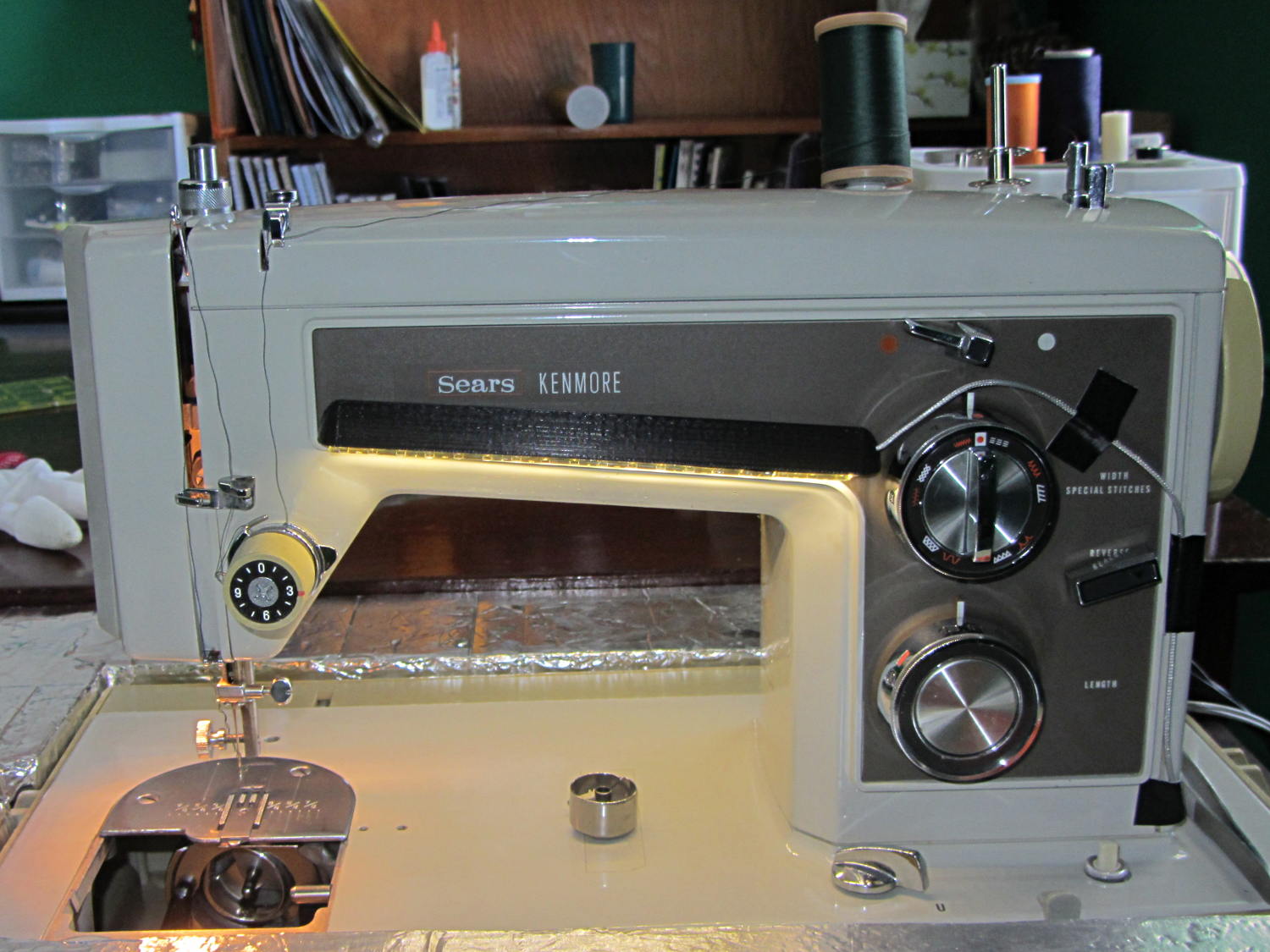
The front LEDs have a jaunty angle along the bottom of the plastic panel:
Kenmore Model 158 Sewing Machine – LED Lights – front
You can see why I want cool-white LEDs, rather than these warm-white ones, to match the daylight from the window to the right. The wash of orange light from the incandescent bulb inside the end bell has got to go, too.
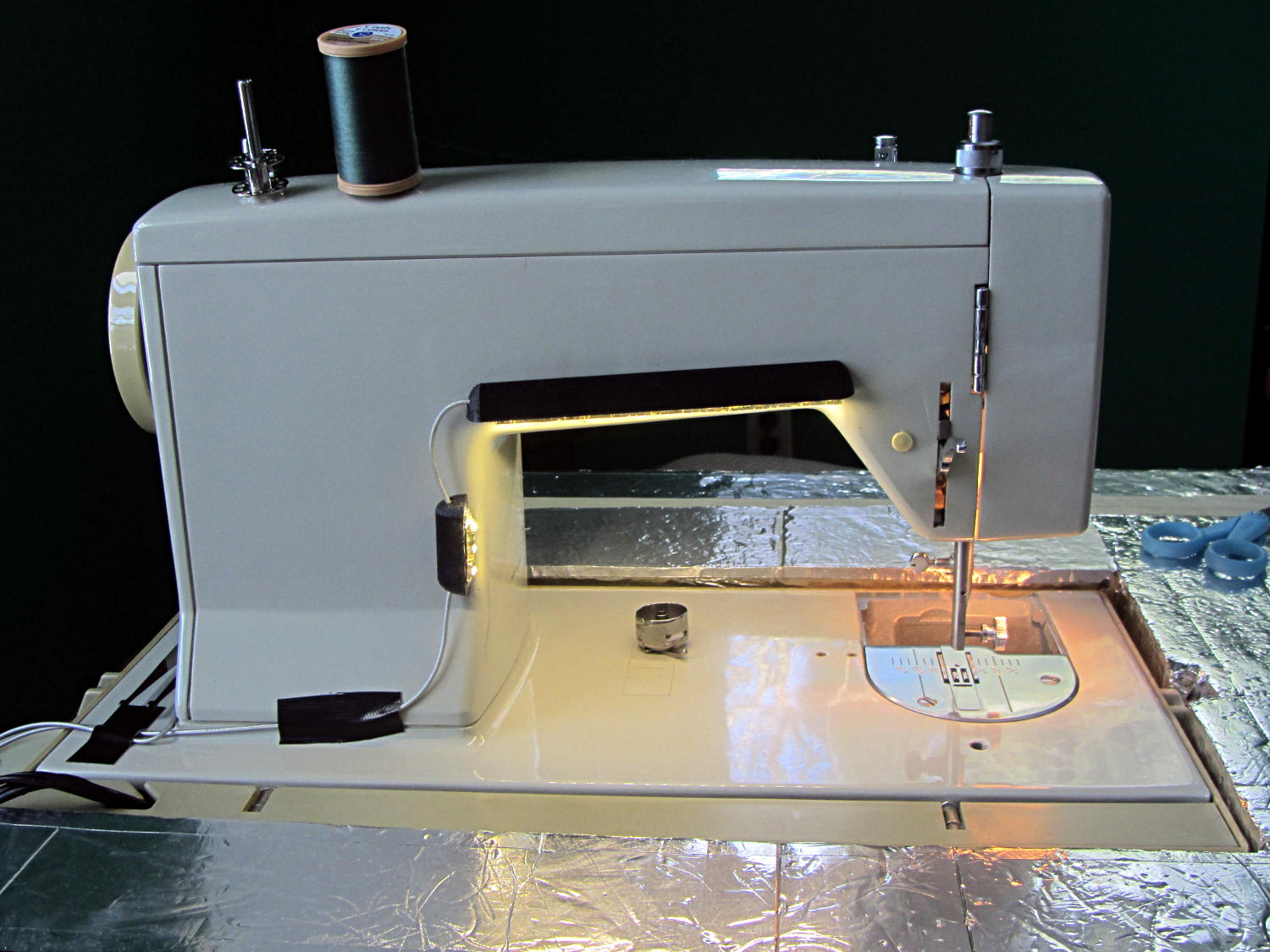
The rear LEDs over the arm may be slightly too close to the opening:
Kenmore Model 158 Sewing Machine – LED Lights – rear
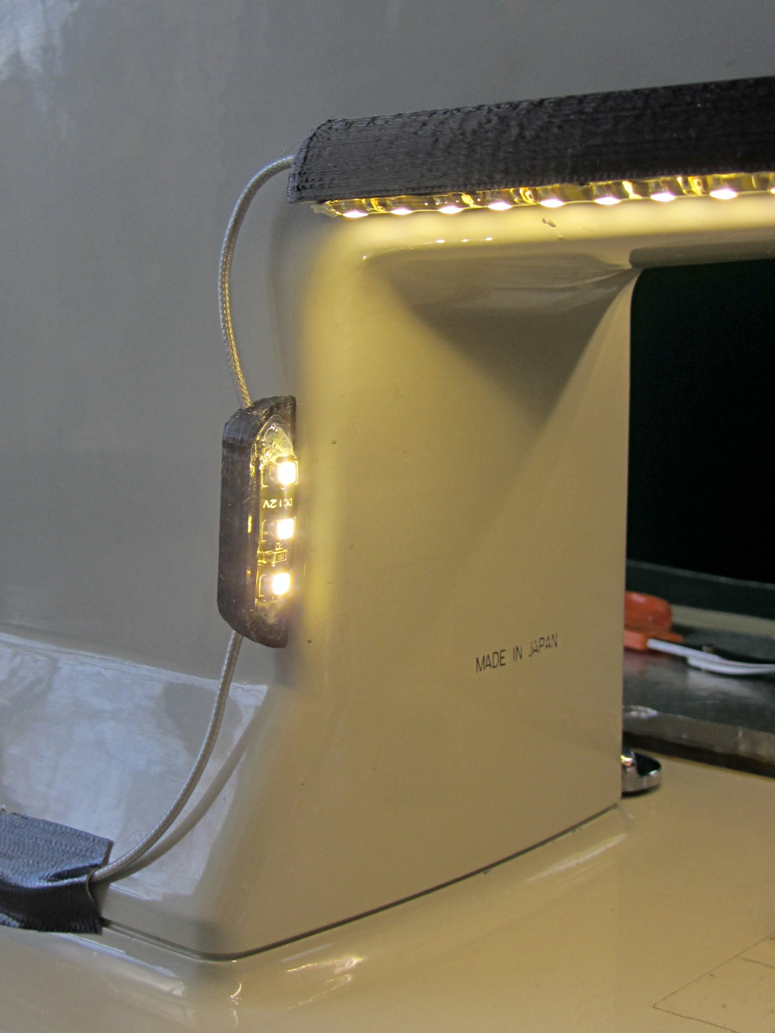
The single-segment strip on the side provides a bit more light for the needle across the opening:
Kenmore Model 158 Sewing Machine – LED Lights – rear detail
Now, I’ll grant you that the strips of of black Gorilla Tape aren’t particularly attractive, but the intent here is to find out whether the LEDs produce enough light, don’t snag the quilt, and generally meet requirements.
My old Thing-O-Matic has new life as the Frank-O-Squid at Squidwrench Galactic HQ, with all the original Makerbot electronics replaced by an Azteeg X3 controller. Over the last several weeks I’ve coaxed it into doing most of the right things at the proper speeds & feeds, so we can now move on to actually making stuff:
Frank-o-Squid in action
The warping on that little digital caliper thumbwheel holder show that I don’t have the tiny-object slowdown settings quite correct, but it’s getting close.
The Marlin firmware is on GitHub. I intended to set it up so that pulling changes from upstream Marlin would be easy, but totally blundered something along the way. I’ll eventually plug the changes from Configuration.h, Configuration_adv.h, and pins.h into a clean branch and start over, but, for now, we’re slowly diverging from consensus reality.
Although the platform still has the Z-min switch over on the right edge, neither the firmware nor Slic3r pay any attention to it. A stub in the startup G-Code sequence does a head fake toward the switch, but doesn’t actually probe it.
I scrapped the original craptastic Makerbot ATX power supply and replaced it with Makergear’s huge 12 V laptop brick that powered the original M2 platform, so the thermal switches on the extruder no longer do anything useful; it’s running bare, pretty much like all other 3D printers.
The Slic3r configuration exports thusly:
# generated by Slic3r 1.0.0RC1 on Mon Mar  3 07:48:29 2014
avoid_crossing_perimeters = 0
bed_size = 105,120
bed_temperature = 100
bottom_solid_layers = 3
bridge_acceleration = 0
bridge_fan_speed = 100
bridge_flow_ratio = 1
bridge_speed = 40
brim_width = 1.0
complete_objects = 0
cooling = 1
default_acceleration = 0
disable_fan_first_layers = 1000
duplicate = 1
duplicate_distance = 6
duplicate_grid = 1,1
end_gcode = ;---- end.gcode starts ----\n; TOM 286 - Al plates + Geared extruder\n; Ed Nisley - KE4ZNU - January 2014\n; Marlin with tweaks for Azteeg X3 with thermocouple\n;- inhale filament blob\nG91\nG1 E-5 F900\nG90\n;- turn off heaters\nM104 S0         ; extruder head\nM140 S0         ; HBP\n;- move to eject position\nG0 Z115 F1000   ; home Z to get nozzle away from object\n;G92 Z115      ; reset Z\nG1 X0 F6000     ; center X axis\nG1 Y35          ; move Y stage forward\n;---- end.gcode ends ----
external_perimeter_speed = 50%
external_perimeters_first = 0
extra_perimeters = 1
extruder_clearance_height = 20
extruder_clearance_radius = 20
extruder_offset = 0x0
extrusion_axis = E
extrusion_multiplier = 0.95
extrusion_width = 0.50
fan_always_on = 0
fan_below_layer_time = 1
filament_diameter = 2.95
fill_angle = 45
fill_density = 0.15
fill_pattern = honeycomb
first_layer_acceleration = 0
first_layer_bed_temperature = 100
first_layer_extrusion_width = 0.50
first_layer_height = 0.25
first_layer_speed = 10
first_layer_temperature = 210
g0 = 0
gap_fill_speed = 30
gcode_arcs = 0
gcode_comments = 0
gcode_flavor = reprap
infill_acceleration = 0
infill_every_layers = 2
infill_extruder = 1
infill_extrusion_width = 0.50
infill_first = 1
infill_only_where_needed = 1
infill_speed = 50
layer_gcode =
layer_height = 0.25
max_fan_speed = 100
min_fan_speed = 35
min_print_speed = 10
min_skirt_length = 3
notes =
nozzle_diameter = 0.4
only_retract_when_crossing_perimeters = 1
ooze_prevention = 0
output_filename_format = [input_filename_base].gcode
overhangs = 1
perimeter_acceleration = 0
perimeter_extruder = 1
perimeter_extrusion_width = 0.50
perimeter_speed = 30
perimeters = 1
post_process =
print_center = 0,0
raft_layers = 0
randomize_start = 1
resolution = 0.05
retract_before_travel = 0.0
retract_layer_change = 0
retract_length = 0.75
retract_length_toolchange = 10
retract_lift = 0
retract_restart_extra = 0
retract_restart_extra_toolchange = 0
retract_speed = 30
rotate = 0
scale = 1
skirt_distance = 2
skirt_height = 1
skirts = 1
slowdown_below_layer_time = 30
small_perimeter_speed = 50%
solid_fill_pattern = rectilinear
solid_infill_below_area = 5
solid_infill_every_layers = 0
solid_infill_extrusion_width = 0.50
solid_infill_speed = 150%
spiral_vase = 0
standby_temperature_delta = -5
start_gcode = ;---- start.gcode begins ----\n; TOM 286 - Al plates + Geared extruder + Zmin platform sense\n; Ed Nisley - KE4ZNU - January 2014\n; Marlin with tweaks for Azteeg X3 with thermocouple\n;\n; Set initial conditions\nG21                 ; set units to mm\nG90                 ; set positioning to absolute\n;----------\n; Begin heating\nM104 S[first_layer_temperature]         ; extruder head\nM140 S[first_layer_bed_temperature]	; start bed heating\n;----------\n; Home axes\nG28 X0 Y0 Z0\nG92 X-53.5 Y-58.5 Z114.5\n;----------\n; Initial nozzle wipe to clear snot for Z touchoff\nG1 X0 Y0 Z3.0 F1000     ; pause at center to build confidence\nG4 P1000\nG1 Z10                  ; ensure clearance\nG1 X39 Y-58.0 F1000    ; move to front, avoid wiper blade\nG1 X55                  ; to wipe station\nG1 Z6.0                 ; to wipe level\nM116                    ; wait for temperature settling\nG1 Y-45 F500            ; slowly wipe nozzle\n;-----------------------------------------------\n; Z platform height touchoff\n; Make sure the XY position is actually over the switch!\n; Home Z downward to platform switch\n; Compensate for 0.05 mm backlash in G92: make it 0.05 too low\nG1 X56.0 Y8.2 F5000\nG1 Z4.0 F1000     ; get over build platform switch\n;G1 Z0 F50                    ; home downward very slowly\n;G92 Z1.45                    ; set Z-min switch height\nG1 Z6.0 F1000                ; back off switch to wipe level\n;-----------------------------------------------\n; Prime extruder to stabilize initial pressure\nG1 X55 Y-45 F5000   ; set up for wipe from rear\nG1 Y-58.0 F500      ; wipe to front\nG91                 ; use incremental motion for extrusion\nG1 F100               ; set decent rate\nG1 E10              ; extrude enough to get good pressure\nG1 F2000            ; set for fast retract\nG1 E-1.0            ; retract\nG90                 ; back to absolute motion\nG1 Y-45 F1000       ; wipe nozzle to rear\n;----------\n; Set up for Skirt start in right front corner\n; Compensate for Z backlash: move upward from zero point\nG1 X40 Y-40 F5000\nG1 Z0.0 F1000     ; kiss platform\nG1 Z0.2 F1000       ; take up Z backlash to less than thread height\n;G92 E1.0            ; preset to avoid huge un-Reversal blob\n;G1 X0 Y0\n;---- start.gcode ends ----
start_perimeters_at_concave_points = 1
start_perimeters_at_non_overhang = 1
support_material = 0
support_material_angle = 0
support_material_enforce_layers = 0
support_material_extruder = 1
support_material_extrusion_width = 0.50
support_material_interface_extruder = 1
support_material_interface_layers = 3
support_material_interface_spacing = 0
support_material_pattern = honeycomb
support_material_spacing = 2.5
support_material_speed = 60
support_material_threshold = 0
temperature = 210
thin_walls = 1
threads = 2
toolchange_gcode =
top_infill_extrusion_width = 0.50
top_solid_infill_speed = 50%
top_solid_layers = 3
travel_speed = 150
use_firmware_retraction = 0
use_relative_e_distances = 0
vibration_limit = 0
wipe = 0
z_offset = 0
All of that should become three TOM286 - Default sub-profiles.
The Pronterface configuration looks like this:
set port /dev/ttyUSB0
set monitor True
set last_bed_temperature 100.0
set last_temperature 210.0
set baudrate 115200
set temperature_abs 210
set xy_feedrate 5000
set z_feedrate 1000
set build_dimensions 110.00x120.00x117.00+0.00+0.00+0.00+0.00+0.00+0.00
set extruders 1
set slic3rintegration True
set tempgauges True
set preview_extrusion_width 0.4
set e_feedrate 100
set last_extrusion 3
set last_file_path /home/ed/Documents/Thing-O-Matic/Calibration/Thread Thickness
set recentfiles ["/home/ed/Documents/Thing-O-Matic/Calibration/Thread Thickness/Caliper Thumbwheel Holder.gcode", "/home/ed/Documents/Thing-O-Matic/Calibration/Thread Thickness/Thinwall Open Box.gcode", "/home/ed/Documents/Thing-O-Matic/Calibration/Thread Thickness/Platform Level.gcode", "/home/ed/Documents/Thing-O-Matic/Calibration/Circle Diameter Calibration/Small Circle Cal - M2 0.2 mm.gcode", "/home/ed/Documents/Thing-O-Matic/Calibration/Circle Diameter Calibration/Small Circle Cal - TOM.gcode"]
As you can see, it’s all running from a directory on my old laptop. The next step involves migrating everything to a dedicated PC next to the printer, so nobody else need worry about this stuff…
Mary’s Sears Kenmore Model 158 sewing machine arm has a flat rear surface and a plastic plate on the front, so double-sided adhesive foam tape can hold a straight mount in place; we rejected putting strips under the arm to avoid snagging on the quilts as they pass by. So, with LEDs in hand, these are the mounts…
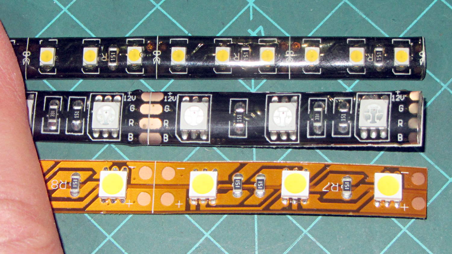
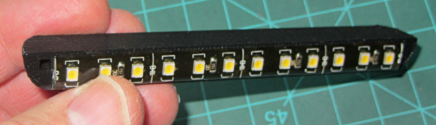
LED strip lights must have strain relief for their wires, as our Larval Engineer discovered the hard way on her longboard ground lighting project, and I wanted nice endcaps to avoid snagging on the fabric, so the general idea was a quarter-round rod with smooth endcaps and a hole to secure the wire. Some experiments showed that the acrylic (?) LED encapsulation directed the light downward, thus eliminating the need for a shade.
So, something like this will do for a first pass:
LED Strip Light Mount – bottom view
The overall dimensions for the LED mounts:
Length: N x 25 mm, plus endcap radii
Front-to-back width: 10 mm to allow for strip variation and 1 mm protection
Top-to-bottom height: 12 mm to fit double-sided foam sticky squares
Wire channels: 3 mm diameter or square cross-section
If there’s not enough light, I think a double-wide mount with two parallel LED strips would work.
After a bit of screwing around with additive endcaps that produced catastrophically non-manifold solid models, I figured out the proper subtractive way to build the mounts: the endcaps actually define the overall shape of the mount.
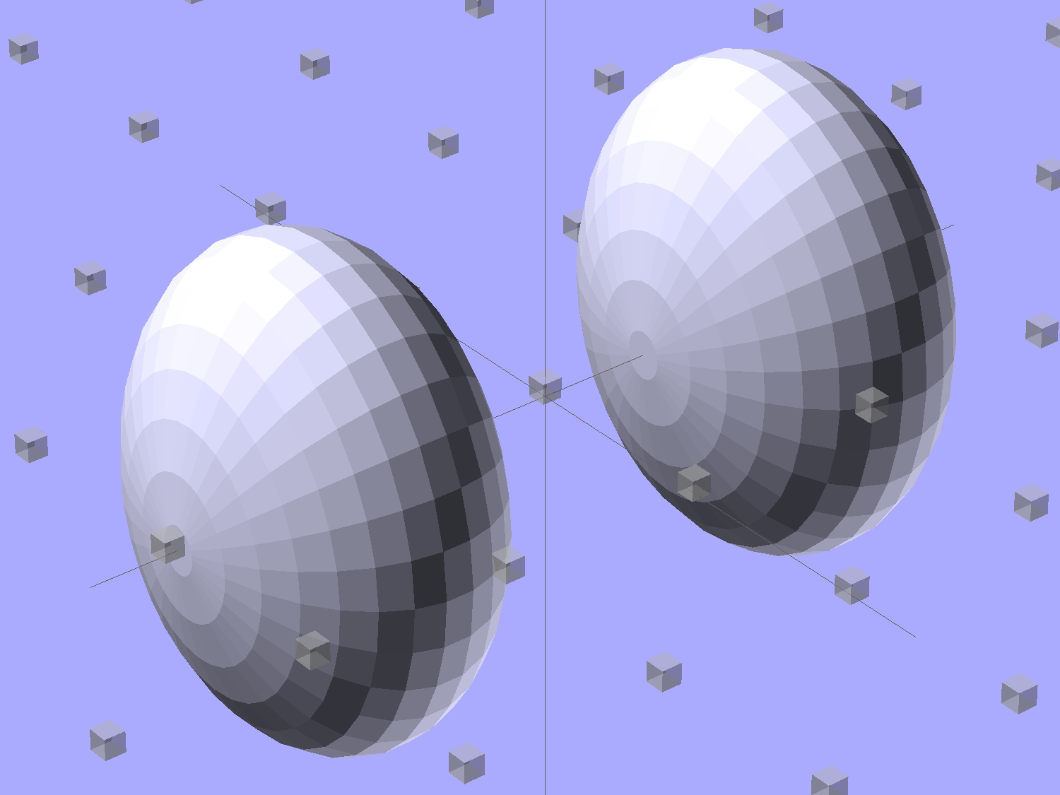
Start by placing a pair of spheroids, with radii matching the strip dimensions, so that their outer poles match the desired overall length:
Strip Light Mount – end cap spheroids – whole
The north/south poles must face outward, so that the equal-angle facets along the equators match up with what will become the mount body: rotate the spheroids 90° around the Y axis. The centers lie at the ends of the LED segments; the model shown here has a single 25 mm segment.
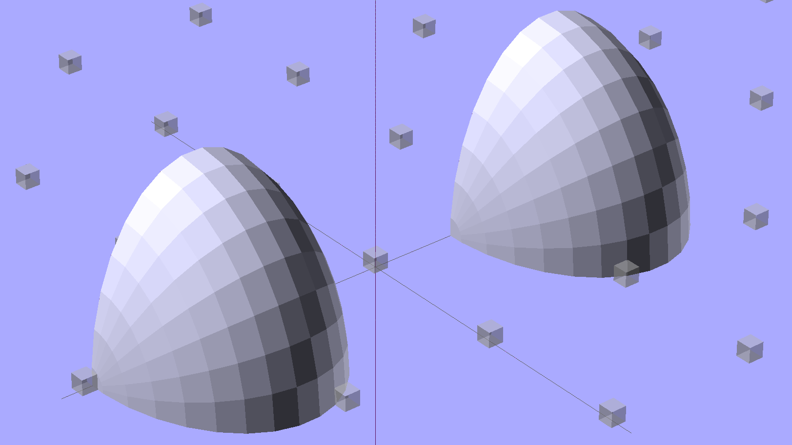
Then hack off three quadrants:
Strip Light Mount – end cap spheroids
That leaves two orange-segment shapes that define the endcaps:
Strip Light Mount – end caps – shaped
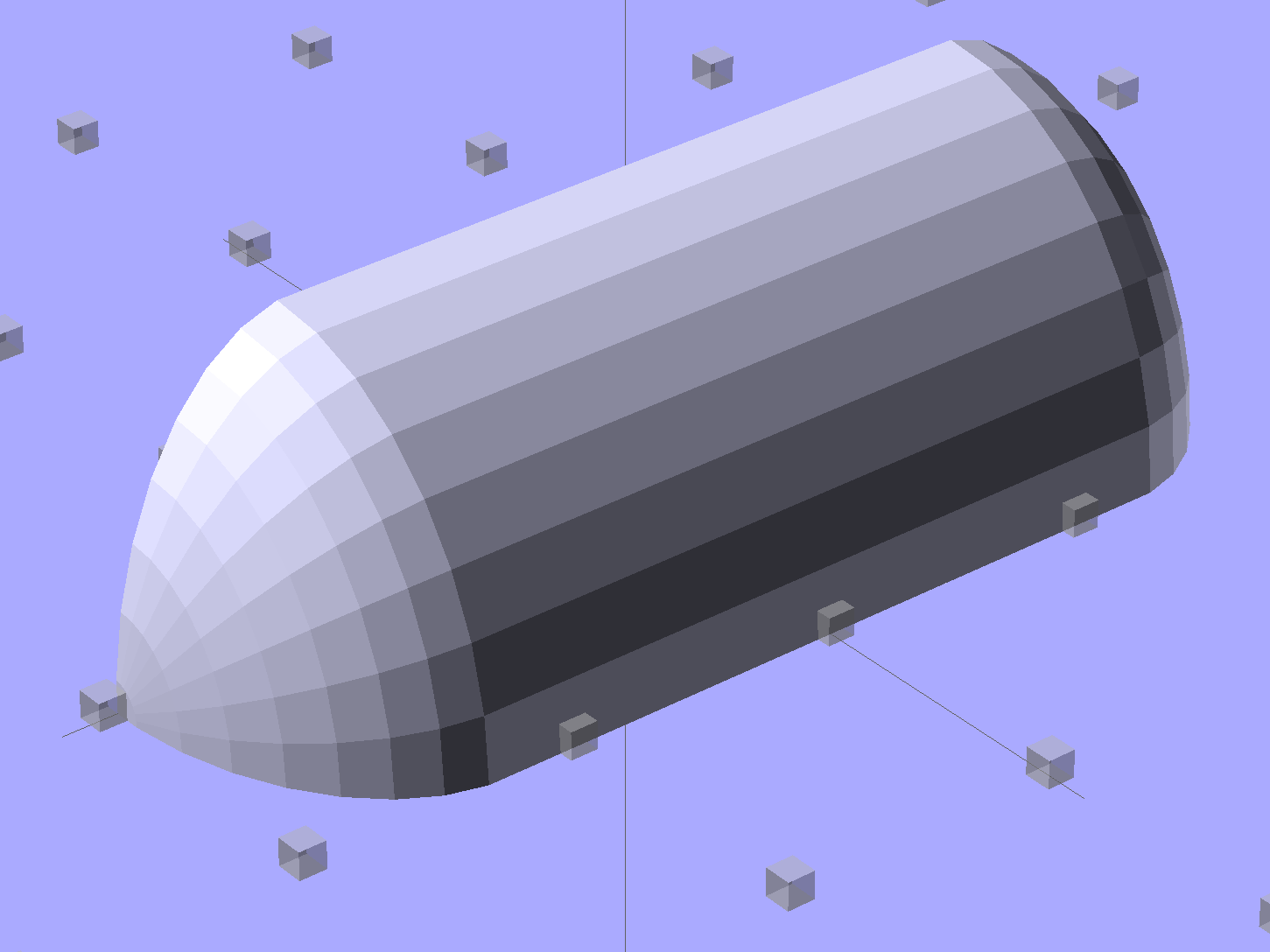
Here’s the key step that took me far too long to figure out. Shrinkwrapping the endcaps with the hull() function finesses the problem of matching the body facets to the endcap facets:
Strip Light Mount – end caps – hull
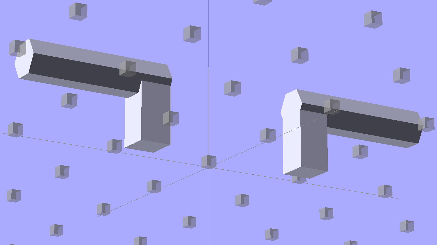
Model the wire channels as positive volumes that will be subtracted from the mount. The Channels layout shows both channels separated by a short distance:
Strip Light Mount – positive wire channels
The horizontal hexagons started as squares, but that looked hideous on the rounded endcaps.
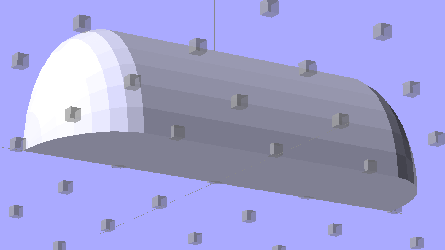
Seen from the bottom, the mount starts like this:
Strip Light Mount – no wiring channels
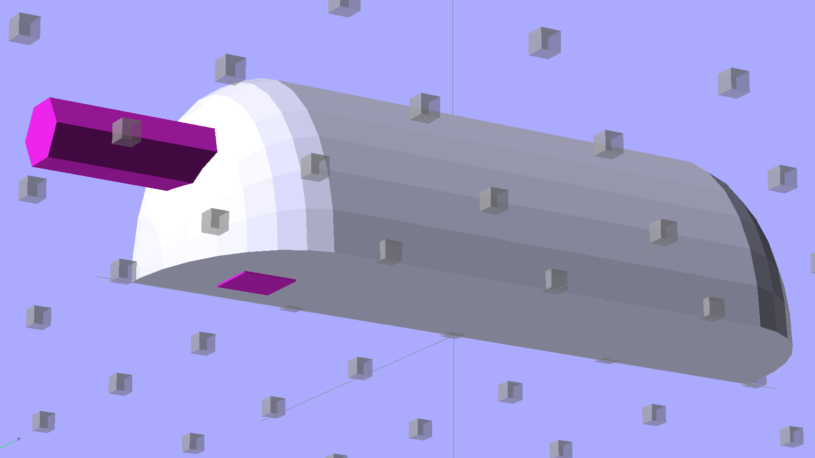
Position and subtract a wire channel:
Strip Light Mount – visible wire channel
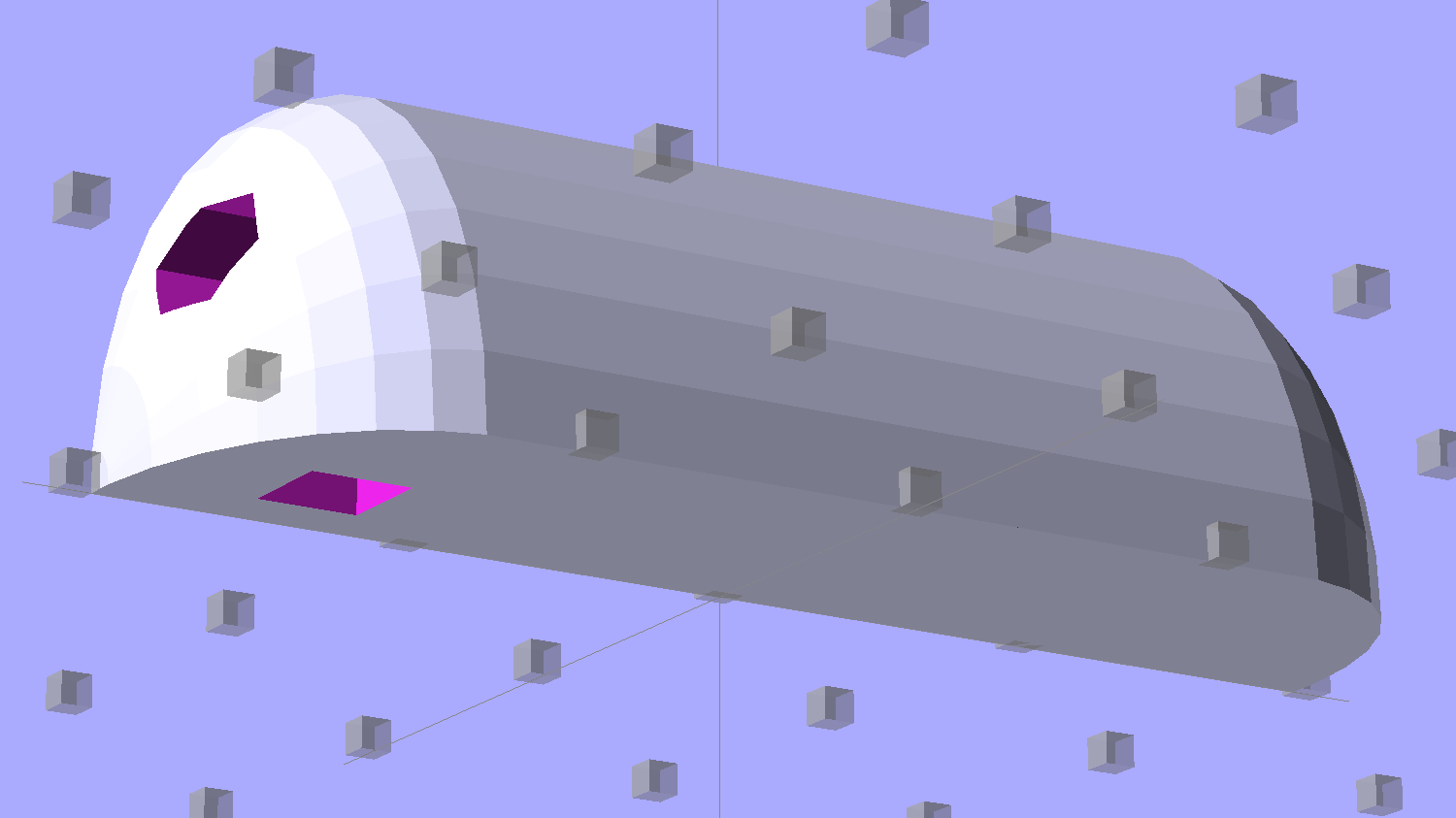
Which leaves the final solid model as a single, manifold object:
Strip Light Mount – complete
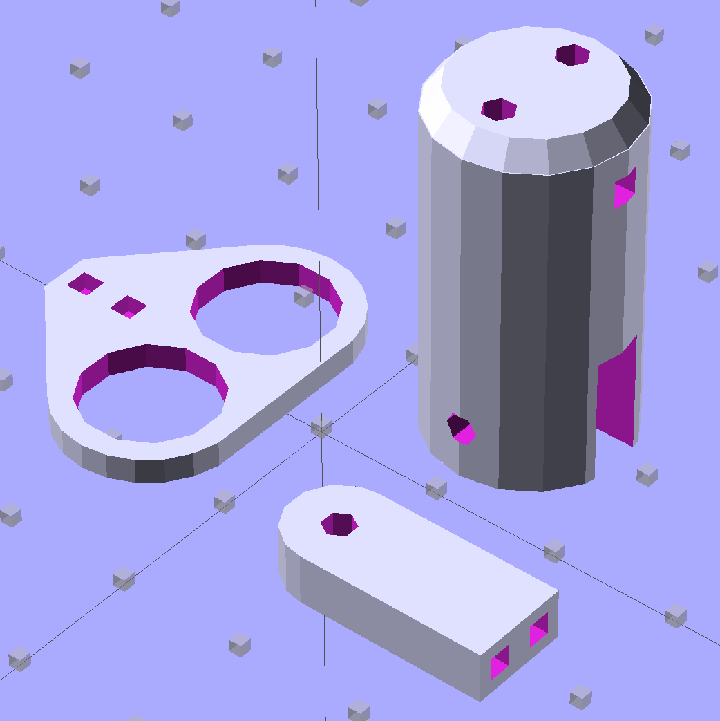
The module generating the mount takes three parameters: the number of LED segments and two string variables that determine whether to punch a channel in each endcap. Instantiate the module three times with suitable parameters to get a trio of LED mounts, all laid out for 3D printing:
Strip Light Mount – build layout
They built just exactly like those models would suggest; the M2 produces dependable results.
The OpenSCAD source code:
// LED Strip Lighting Brackets for Kenmore Model 158 Sewing Machine
// Ed Nisley - KE4ZNU - February 2014
Layout = "Strip"; // Build Show Channels Strip
//- Extrusion parameters must match reality!
// Print with 2 shells and 3 solid layers
ThreadThick = 0.20;
ThreadWidth = 0.40;
HoleWindage = 0.2; // extra clearance
Protrusion = 0.1; // make holes end cleanly
AlignPinOD = 1.70; // assembly alignment pins: filament dia
inch = 25.4;
function IntegerMultiple(Size,Unit) = Unit * ceil(Size / Unit);
//----------------------
// Dimensions
Segment = [25.0,10.0,3.0]; // size of each LED segment
WireChannel = 3.0; // wire routing channel
StripHeight = 12.0; // sticky tape width
StripSides = 8*4;
DefaultLayout = [1,"Wire","NoWire"];
EndCap = [(2*WireChannel + 1.0),Segment[1],StripHeight]; // radii of end cap spheroid
EndCapSides = StripSides;
CapSpace = 2.0; // build spacing for endcaps
BuildSpace = 1.5*Segment[1]; // spacing between objects on platform
//----------------------
// Useful routines
module PolyCyl(Dia,Height,ForceSides=0) { // based on nophead's polyholes
Sides = (ForceSides != 0) ? ForceSides : (ceil(Dia) + 2);
FixDia = Dia / cos(180/Sides);
cylinder(r=(FixDia + HoleWindage)/2,
h=Height,
$fn=Sides);
}
module ShowPegGrid(Space = 10.0,Size = 1.0) {
RangeX = floor(100 / Space);
RangeY = floor(125 / Space);
for (x=[-RangeX:RangeX])
for (y=[-RangeY:RangeY])
translate([x*Space,y*Space,Size/2])
%cube(Size,center=true);
}
//-- The negative space used to thread wires into the endcap
module MakeWireChannel(Which = "Left") {
HalfSpace = EndCap[0] * ((Which == "Left") ? 1 : -1);
render(convexity=2)
translate([0,EndCap[1]/3,0])
intersection() {
union() {
cube([2*WireChannel,WireChannel,EndCap[2]],center=true);
translate([-2*EndCap[0],0,EndCap[2]/2])
rotate([0,90,0]) rotate(180/6)
PolyCyl(WireChannel,4*EndCap[0],6);
}
translate([HalfSpace,0,(EndCap[2] - Protrusion)]) {
cube(2*EndCap,center=true);
}
}
}
//-- The whole strip, minus wiring channels
module MakeStrip(Layout = DefaultLayout) {
BarLength = Layout[0] * Segment[0]; // central bar length
hull()
difference() {
for (x = [-1,1]) // endcaps as spheroids
translate([x*BarLength/2,0,0])
resize(2*EndCap) rotate([0,90,0]) sphere(1.0,$fn=EndCapSides);
translate([0,0,-EndCap[2]])
cube([2*BarLength,3*EndCap[1],2*EndCap[2]],center=true);
translate([0,-EndCap[1],0])
cube([2*BarLength,2*EndCap[1],3*EndCap[2]],center=true);
}
}
//-- Cut wiring channels out of strip
module MakeMount(Layout = DefaultLayout) {
BarLength = Layout[0] * Segment[0];
difference() {
MakeStrip(Layout);
if (Layout[1] == "Wire")
translate([BarLength/2,0,0])
MakeWireChannel("Left");
if (Layout[2] == "Wire")
translate([-BarLength/2,0,0])
MakeWireChannel("Right");
}
}
//- Build it
ShowPegGrid();
if (Layout == "Channels") {
translate([ EndCap[0],0,0]) MakeWireChannel("Left");
translate([-EndCap[0],0,0]) MakeWireChannel("Right");
}
if (Layout == "Strip") {
MakeStrip(DefaultLayout);
}
if (Layout == "Show") {
MakeMount(DefaultLayout);
}
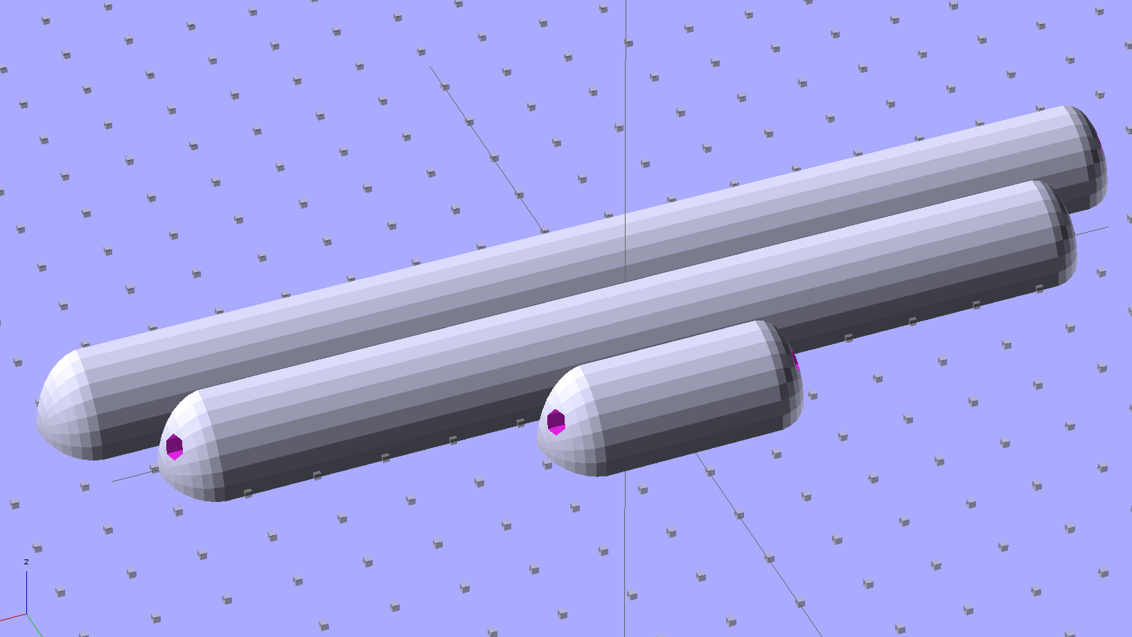
if (Layout == "Build") {
translate([0,BuildSpace,0]) MakeMount([1,"Wire","Wire"]); // rear left side, vertical
translate([0,0,0]) MakeMount([5,"Wire","NoWire"]); // rear top, across arm
translate([0,-BuildSpace,0]) MakeMount([6,"NoWire","Wire"]); // front top, across arm
}
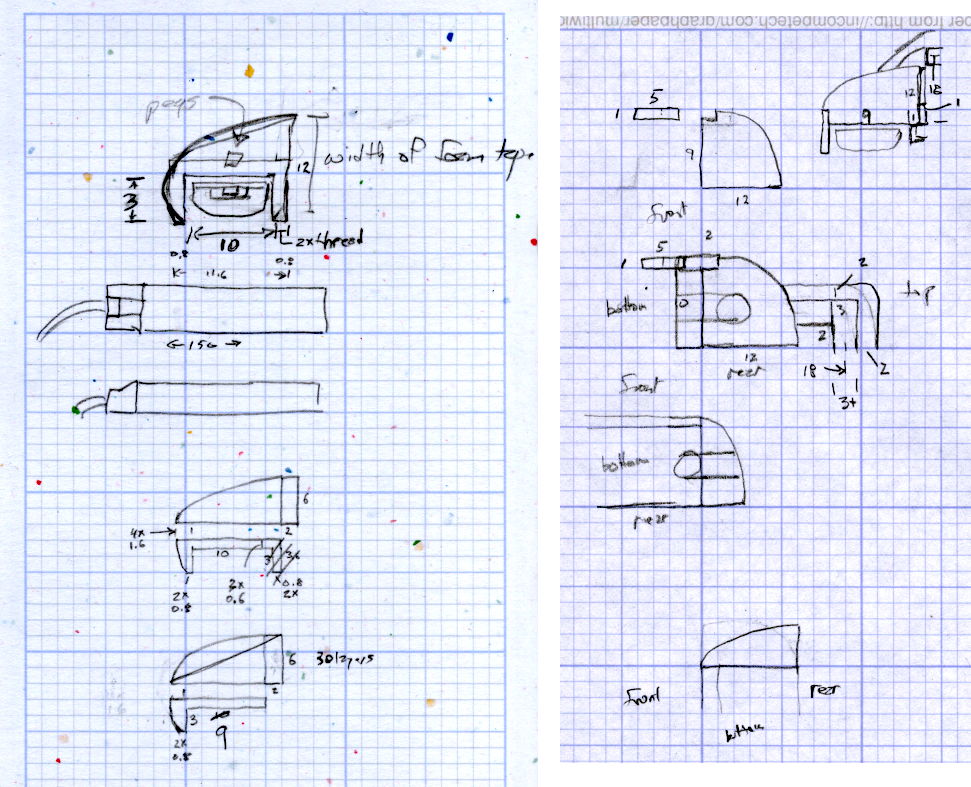
The original design doodles, which bear a vague resemblance to the final mounts:
LED Strip Light Mounts – Original Design Sketches
The little snood coming out of the top would hide a wire going through a hole drilled in the capital-S of “Sears” on the front panel, but I came to my senses long before implementing that idea…