Because the ET227 transistor acts as a current limiter, the motor current waveform has flat tops at the level set by the DAC voltage. However, the current depends strongly on the temperature of all those transistor junctions, with some commutation noise mixed in for good measure, so the firmware must measure the actual current to know what’s going on out there.
Here’s one way to pull that off:
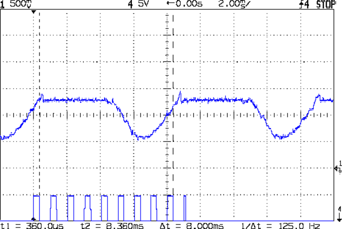
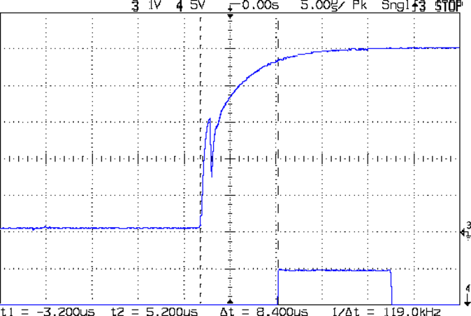
The upper waveform shows the motor current sporting flat tops at 650 mA.
The lower waveform marks the current measurement routine, with samples taken just before the falling edge of the first nine pulses. The (manually tweaked) delay between the samples forces them to span one complete cycle of the waveform, but they’re not synchronized to the power line. Remember that the motor runs from a full wave rectifier, so each “cycle” in that waveform is half of a normal power line cycle.
Given an array containing those nine samples, the routine must return the maximum value of the waveform, ignoring the little glitch at the start of the flat top and taking into consideration that the waveform won’t have a flat top (or much of a glitch) when the current “limit” exceeds the maximum motor current.
After a bit of fumbling around with the scope and software, the routine goes like this:
- Collect samples during one current cycle
- Sort in descending order
- Ignore highest sample
- Return average of next two highest samples
Given that the array has only nine samples, I used a quick-and-dirty bubble sort. The runt pulse at the end of the series in the bottom waveform brackets the sort routine, so it’s not a real time killer.
Seeing as how this is one of the very few occasions I’ve had to sort anything, I wheeled out the classic XOR method of exchanging the entries. Go ahead, time XOR against swapping through a temporary variable; it surely doesn’t make any difference at all on an 8-bit microcontroller.
The sampling code, with all the tracing stuff commented out:
//------------------
// Sample current along AC waveform to find maximum value
//	this is blocking, so don't call it every time around the main loop!

#define NUM_I_SAMPLES	9

unsigned int SampleCurrent(byte PinNum) {

unsigned int Samples[NUM_I_SAMPLES];
unsigned int AvgSample;
byte i,j;

//	digitalWrite(PIN_SYNC,HIGH);
	for (i=0; i < NUM_I_SAMPLES; i++) {				// collect samples
//		digitalWrite(PIN_SYNC,HIGH);
		Samples[i] = ReadAI(PinNum);
//		digitalWrite(PIN_SYNC,LOW);
		delayMicroseconds(640);
	}
//	digitalWrite(PIN_SYNC,LOW);

//	digitalWrite(PIN_SYNC,HIGH);							// mark start of sorting
	for (i=0; i < (NUM_I_SAMPLES - 1); i++)
		for (j=0 ; j < (NUM_I_SAMPLES - 1 - i); j++)
			if (Samples[j] < Samples[j+1]) {
				Samples[j] ^= Samples[j+1];					// swap entries!
				Samples[j+1] ^= Samples[j];
				Samples[j] ^= Samples[j+1];
			}
//	digitalWrite(PIN_SYNC,LOW);								// mark end of sorting

//	printf("Samples: ");
//	for (i=0; i < NUM_I_SAMPLES; i++)
//		printf("%5d,",Samples[i]);

	AvgSample = (Samples[1] + Samples[2])/2;				// discard highest sample
//	printf(" [%5d]\r\n",AvgSample);

	return AvgSample;

}