The LED mounting plate inside the sewing machine’s end cap sits 30° from the vertical axis of the needle. Even though the surface-mount LED emitters have a broad pattern, it seemed reasonable to aim them toward the needle to put the brightest spot where it’s needed.
The LEDs must have enough heatsinking to pull 2+ W out of the solder pads, so I figured I’d just epoxy them firmly to the mounting plate, rather than try to gimmick up a circuit board that would interpose a fiberglass slab in the thermal path.
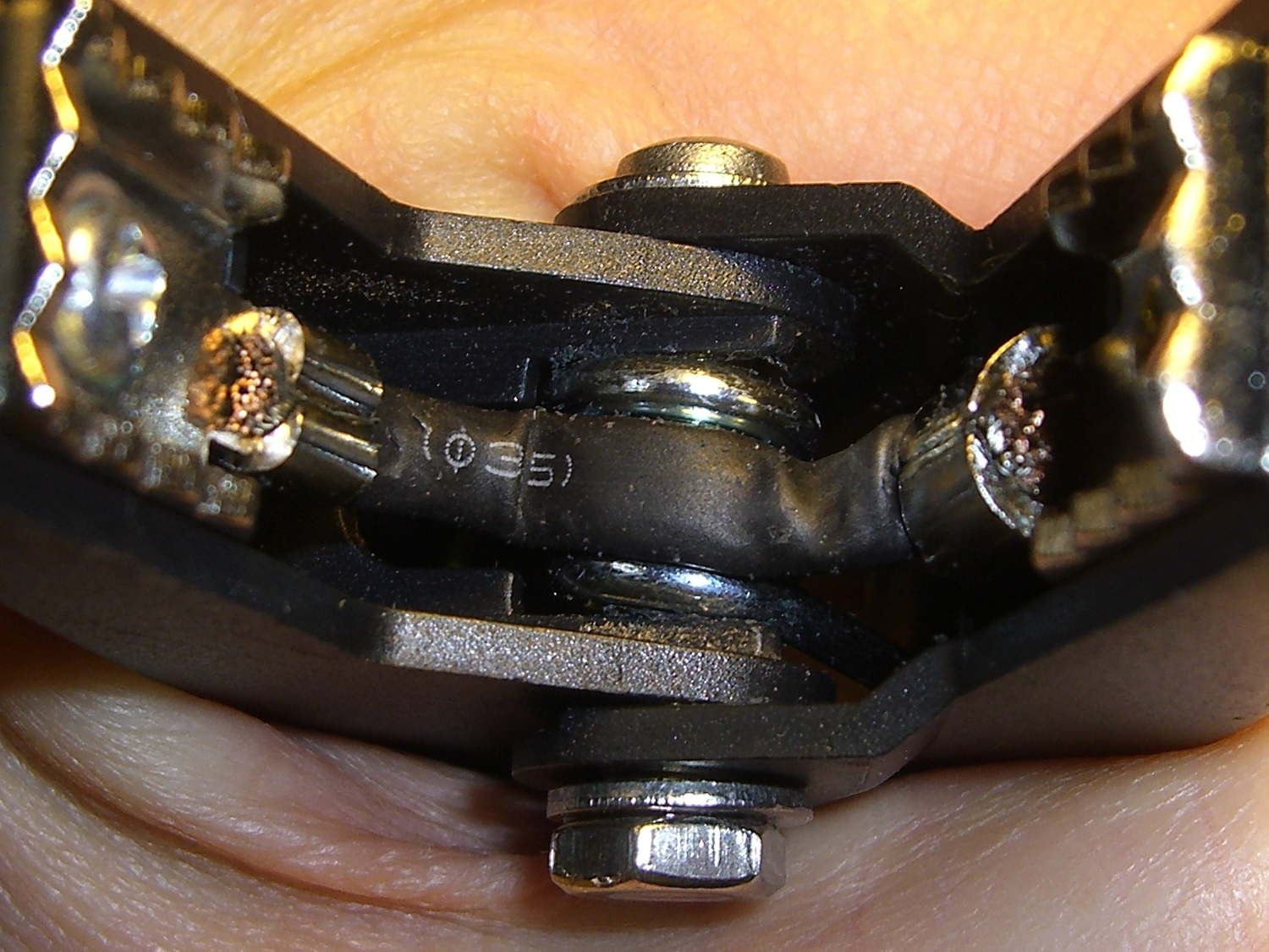
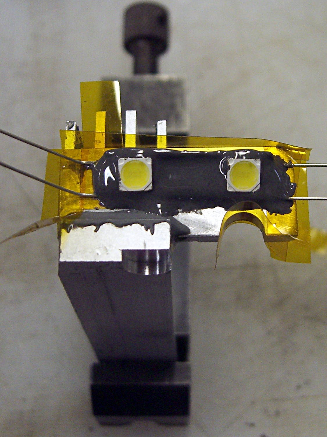
Combine those two requirements and you (well, I) get a wire fixture that provides both power and alignment:

The LED body is 5 mm square, sin(30°) = 0.5, and the rear wire raises contact end by 2.5 mm. This still isn’t an exact science; if the center of the beam lands in the right time zone, that’s close enough.
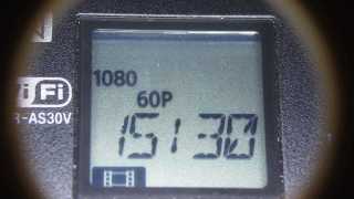
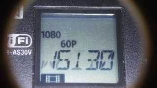
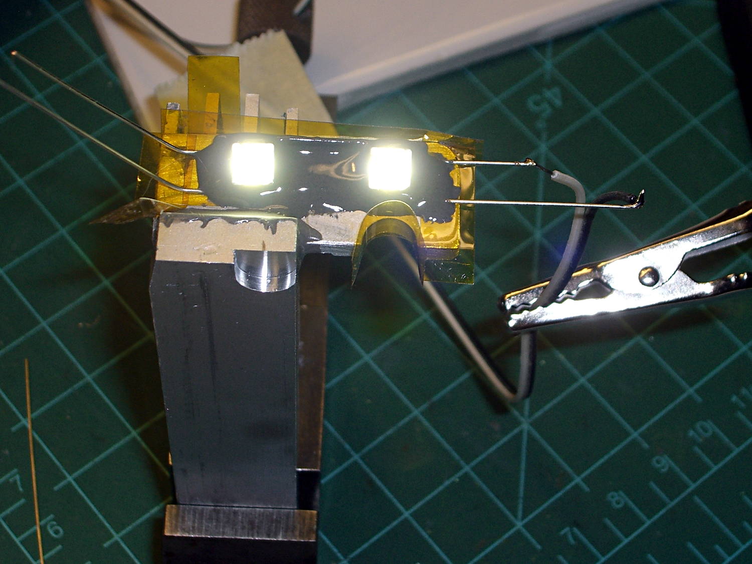
Testing the LED assembly at low current before entombing it shows the emitters have six chips in series (clicky for more dots):
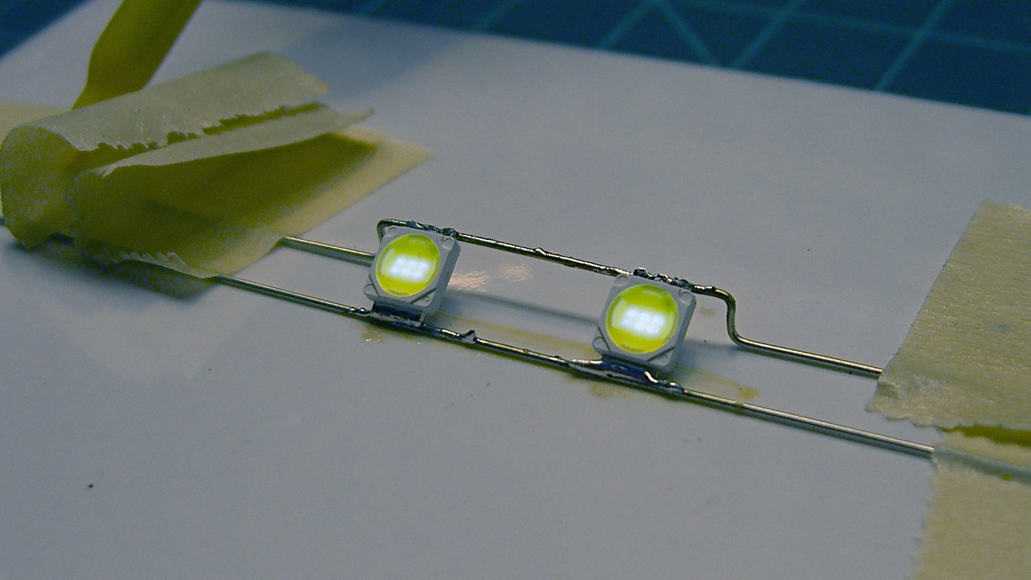
The grotendous solder job follows my “The Bigger the Blob, the Better the Job” principle, modulated by the difficulty of getting a smooth finish on bare wires. Indeed, the first wires I painstakingly bent, set up, and soldered turned out to have an un-solderable surface, much like the header pins from a while ago. That hank of wire now resides in the copper cable recycling bucket; you’re looking at Version 1.1.
Two strips of Kapton tape under the ends of the wires hold them off the (scoured and wiped clean!) aluminum plate, with more tape forming a dam around the nearest edges:
Despite being steel-filled, JB Weld remains nonconductive, the epoxy-filled gap under the wires insulates them from the plate, the wires aren’t shorted together, and there’s a great thermal bond to the heatsink. Good stuff, that JB Weld!
A view from the back side shows the epoxy sagging over the wires before I added another blob:
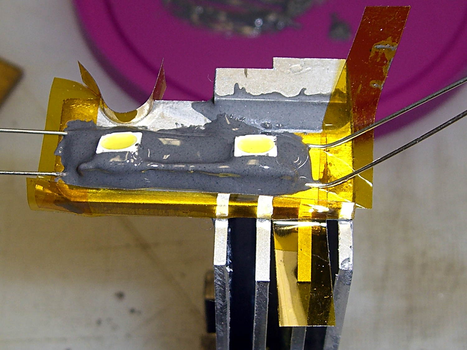
The LED assembly just sits there, without being anchored, until the epoxy cures. The epoxy remains thick enough (in the rather chilly Basement Laboratory) so that it doesn’t exactly pour, can be eased into place without too much muss & fuss, and stays pretty much where it’s put.
After the epoxy stiffened a bit, I gingerly positioned stranded wires not-quite-touching the LED wires and applied a dot of solder to each. Powering the LEDs from a bench supply at 500 mW each took the chill off the heatsink and encouraged proper curing:
Fast forward to the next day, return the heatsink to the Sherline, and drill a hole for the power cable. It’s centered between the wires in Y and between the fins in X, which is why I couldn’t drill before mounting the LEDs:

It’s not like I’m building this from any specs…
Trim the wires, solder the cable in place, cover the wire ends & joints with JB KwikWeld epoxy, and it’s done:
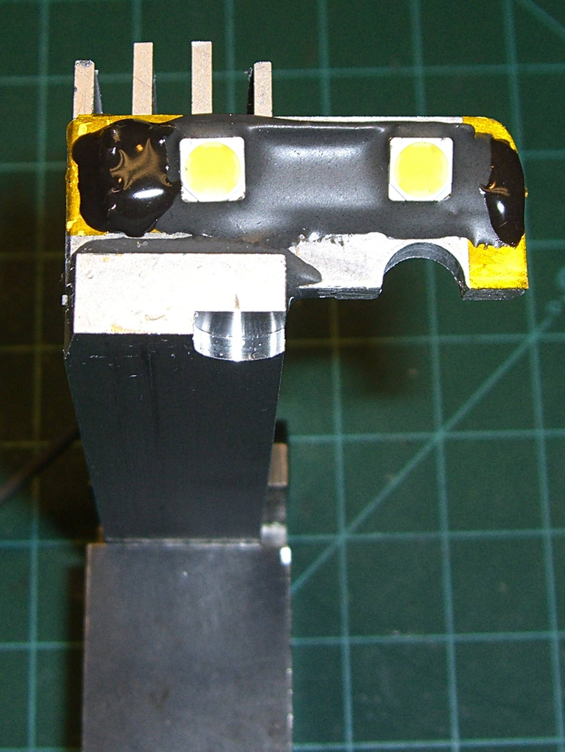
With the LEDs running their 230 mA rated current, the entire heatsink gets pleasantly warm and the mounting plate isn’t much warmer than that. I loves me a good JB Weld job…
However, I suspect they’ll shine too brightly at full throttle, which means an adjustable power supply looms on the horizon…