Ed Nisley's Blog: Shop notes, electronics, firmware, machinery, 3D printing, laser cuttery, and curiosities. Contents: 100% human thinking, 0% AI slop.
For a pure indicator, it’d be easier to slap a spot on the screen with the Adafruit GFX library’sfillRect() function. If you’re setting up a generic button handler, then button bitmap images make more sense.
Being that type of guy, I want a visible indication that the firmware continues trudging around the Main Loop. The standard Arduino LED works fine for that (unless you’re using hardware SPI), but the Adafruit 2.8 inch Touch-screen TFT LCD shield covers the entire Arduino board, so I can’t see the glowing chip.
Given a few spare pixels and the Adafruit GFX library, slap a mood light in the corner:
Adafruit TFT – heartbeat spot
The library defines the RGB color as a 16 bit word, so this code produces a dot that changes color every half second around the loop() function:
millis() produces an obvious counting sequence of colors. If that matters, you use random(0x10000).
A square might be slightly faster than a circle. If that matters, you need an actual measurement in place of an opinion.
Not much, but it makes me happy…
There’s an obvious extension for decimal values: five adjacent spots in the resistor color code show you an unsigned number. Use dark gray for black to prevent it from getting lost; light gray and white would be fine. Prefix it with a weird color spot for the negative sign, should you need such a thing.
Hexadecimal values present a challenge. That’s insufficient justification to bring back octal notation.
In this day and age, color-coded numeric readouts should be patentable, as casual searching didn’t turn up anything similar. You saw it here first… [grin]
Now that I think about it, a set of tiny buttons that control various modes might be in order.
I ran across your blog on Smart Beaconing and saw something that needed correction.
You state the Turn Slope is in units Degrees / MPH
This is incorrect. Although the term Turn Slope is not a real slope (such as rise/run classically) that is what the originators used albeit incorrectly. They do however correctly attribute the units to MPH * Degrees (a product and hence not really a slope).
In their formula they calculate a turn threshold as:
turn_threshold = min_turn_angle + turn_slope / speed
Looking at the units we see:
= Degrees + (MPH * Degrees) / MPH
which yields
= Degrees + Degrees
Which makes sense. It is too bad that the originators used the wrong term of Turn Slope which confuses most people. A better term would have been Turn Product.
In looking back over that post, I have no idea where or how I got the wrong units, other than by the plain reading of the “variable name”.
As he explained in a followup note:
As for units… I was introduced to making unit balance way back in 1967-1968 science class in HS by a really fine science teacher. It has served me all my life and I’m thankful for that training.
I have ever since told that teacher so!
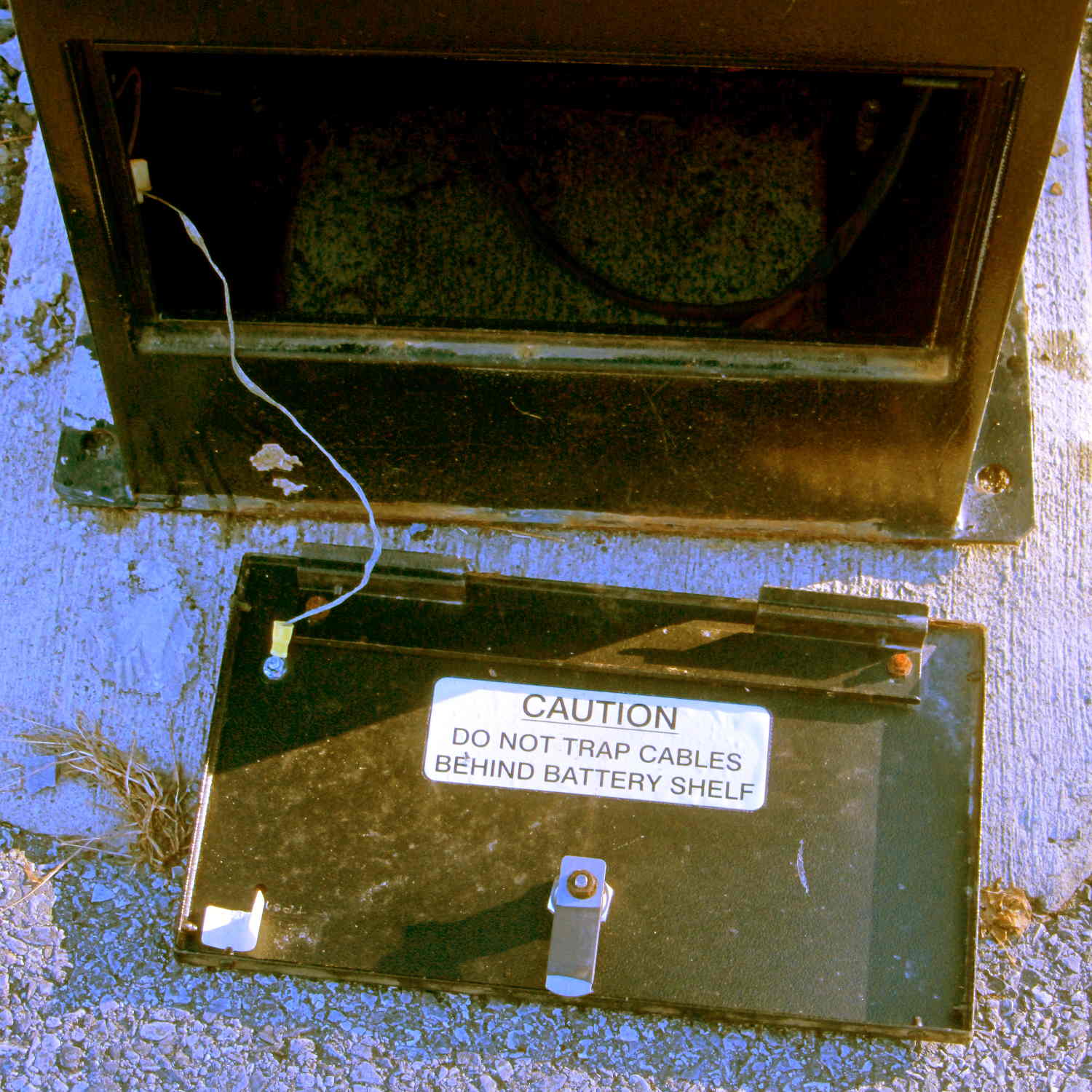
A while back, our Larval Engineer rammed an engineering physics class head-on and sent me a meme image, observing that I’d trained her well: if the units don’t work out, then you’re doing it wrong.
So we took an out-and-back walk across the Walkway Over the Hudson, after which I spotted this amusing sight:
Parking Meter – empty battery box
The horrible color balance comes from using a preset tuned for the M2’s new LED lights, rather than letting the camera figure things out on its own, then fighting it down after cropping.
Anyhow, we did a bit over two miles of walking with outdoor temperature just over freezing. The camera lives in the left cargo pocket of my pants and the spare NB-5L battery in the camera case faces outward. Neither battery would power the camera at ambient temperature; evidently, being that cold reduced their output voltage below the level that the camera would accept.
With a cold battery, the camera grunted, displayed a message about replacing the battery, and promptly shut itself off. Warming one of the batteries boosted its terminal voltage enough to take the picture, which accounts for not getting the proper color balance: I was fully occupied just getting the camera working.
Back home and warmed up, the camera said both batteries were fully charged. They came from the BNF27 lot that produced low terminal voltages, so I’ll reserve them for warmer weather and use the BNI13 lot during the next few months.
The cardboard package liner claims the lithium-ion battery inside our Larval Engineer’s shiny new InstaBoost jump starter is good for 10.8 A·h and and the minuscule inscription on the case truncates it to 10 A·h. Given what I’ve seen for other batteries, either value would be true when measured under the most favorable conditions, but these curves still came as a bit of a surprise (clicky for more dots):
Pilot Instaboost
The three short, abruptly dropping curves come from the main terminals, with the battery clamps attached to similar clamps (with a glitch when they shifted position) plugged into my CBA II/IV battery tester, showing that the InstaBoost shuts off after a few minutes, regardless of load. That makes good sense: don’t connect a lithium battery to a lead-acid battery for more than a few minutes!
The two longer curves come from the 12 V jack on the side and show that it will run until the battery goes flat. Evidently, the internal battery protection circuit cuts out at less than the 10 V minimum I used for these tests.
I didn’t bother testing the USB charging outlet, as I assume it would produce 5 V at 1 A for slightly less than twice as long.
Under the most favorable conditions I could come up with, the actual battery capacity of 3.5 A·h is a third of what it should be. I’d expect that from the usual eBay supplier, not Lowe’s.
Given the cheapnified clamps, perhaps Pilot deliberately gutted the battery capacity to save a few bucks. After all, the customers will never notice. Will they?
Except…
Another customer took his apart and found three 3.6 A·h “high output” (whatever that means) lithium cells in series. In that configuration, the individual cell capacity does not add and the pack should produce about 3.6 A·h. Those curves show it produces slightly less than that when discharged to 10 V, which means the thing works exactly like you’d expect. Indeed, it’s better than a typical second-tier product and much better than typical eBay crap.
The most charitable explanation would be that somebody screwed up, multiplied the number of cells by their individual capacity, put that number in the specs, and everyone downstream ran with it. If the cells were in parallel, then the total capacity in ampere·hours would equal the sum of the cell capacity.
If you change the specs to match the as-built hardware, then, apart from those cheapnified clamps, it’s working just fine…
Even though the current has the usual exponential relationship to the terminal voltage, the slope at 200 mA (100 mA each, assuming they share & share alike) remains low enough that I (think I) can get away with just dialing in a voltage and leaving it at that; changes due to small temperature variations won’t cause meaningful differences in the current.
That’s easier than building an adjustable current regulator, anyway.
The heap disgorged two cheap DC-to-DC boost converters from halfway around the planet, with about the right specs:
So I wired one up to the bench supply, set it for 12 V, turned it on, and wham it maxed out the supply at 3 A with no load on the converter’s output.
Huh.
Adding a suitable load resistor brought the input current down, but the voltage adjustment trimpot didn’t have much effect and the bench supply would still wham hit 3 A with no provocation, so the load resistor didn’t actually make any difference. Eventually, I figured out that simply pressing my finger on the trimpot caused the output to vary wildly.
Given that fairly broad hint, this became obvious:
Boost Converter – trimpot pins
Evidently, I had used the other converter for the previous tests. Huh.
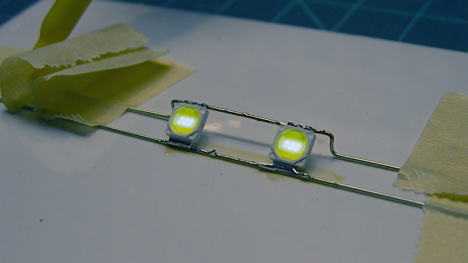
With that trimpot pin soldered in place, the converter worked fine. Eyeballometrically speaking, the LEDs seem bright enough at 100 mA total (50 mA each) for my purposes, which happens at 18-ish V. Dissipating only 2 W won’t require nearly as much heatsink as they’re presently mounted on, although I should wait for warmer weather before concluding that they’re doing OK while crammed inside the end cap.
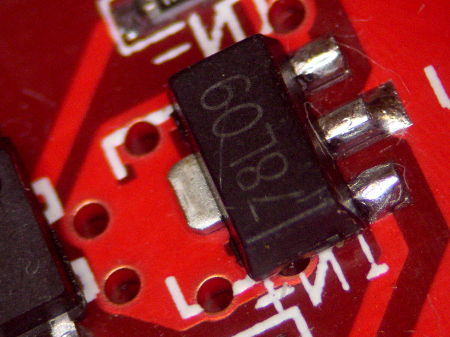
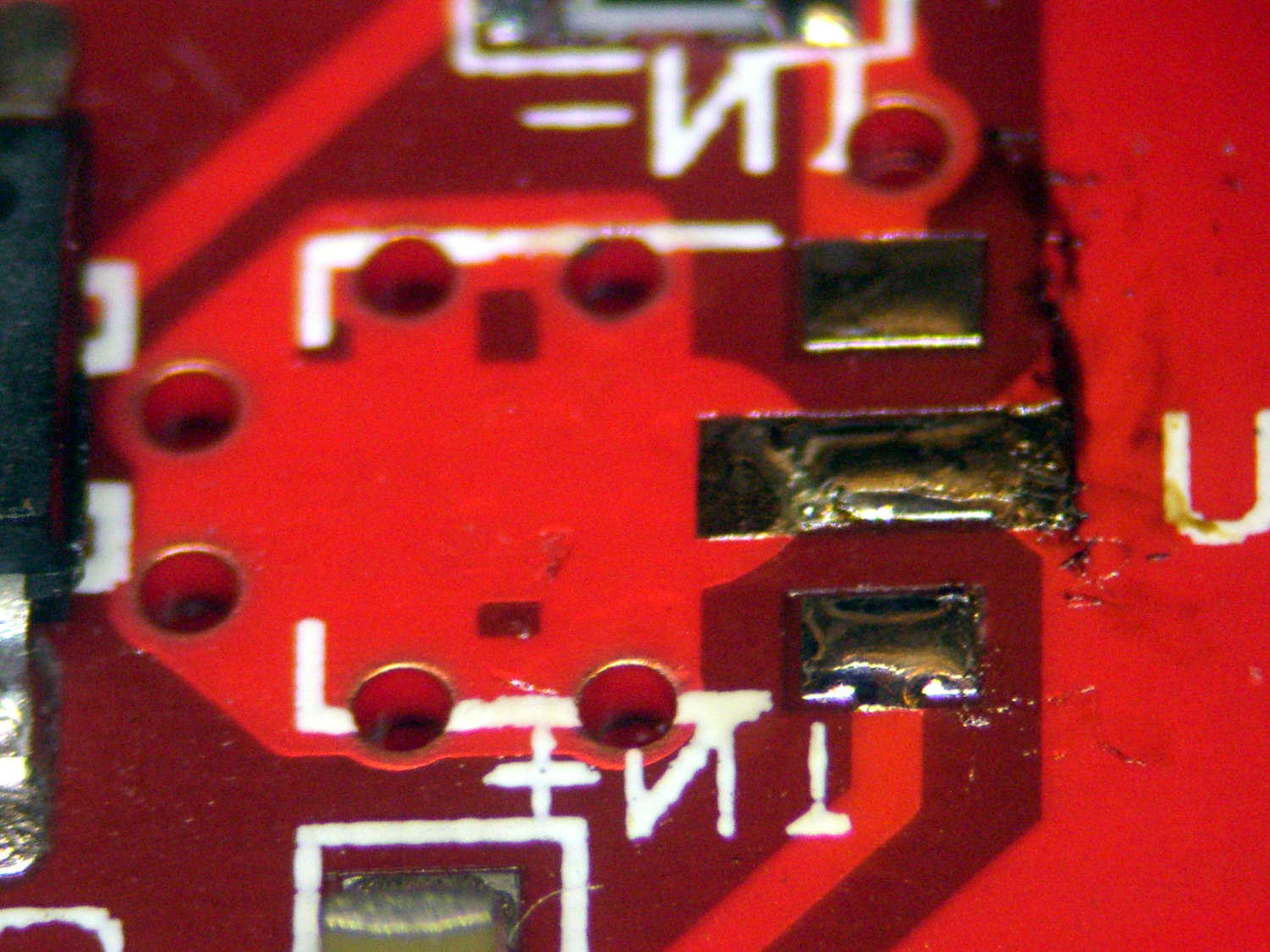
Before declaring victory, I took a closer look at the board and found this mmm oversight:
Boost Converter – masked 78L09 tab
Notice the big pad under the 78L09 regulator, with six thermal vias to an expansive copper pour on the other side of the board, completely covered with red solder mask.
Removing the regulator show the regulator’s footprint didn’t include the tab:
Boost Converter – 78L09 footprint
Maybe they decided, after a careful analysis, that the regulator couldn’t possibly dissipate enough power to warrant the additional solder required for the entire thermal pad. Heck, pocket a fraction of a yuan on ten million boards and you’re livin’ large.
Scraping the mask off, fluxing everything in sight, and soldering the regulator down probably won’t make any difference:
Boost Converter – scraped and soldered
Yes, The Bigger The Blob, The Better The Job strikes again. It does make me feel better and that’s all that counts.