Ed Nisley's Blog: Shop notes, electronics, firmware, machinery, 3D printing, laser cuttery, and curiosities. Contents: 100% human thinking, 0% AI slop.
I should mention the lamp test in case it comes in useful later on…
	digitalWrite(PIN_HEARTBEAT,LOW);	// turn off while panel blinks

	analogWrite(PIN_DIMMING,LEDS_ON);	// enable LED array

	for (byte i=0; i<NUMROWS; i++) {
		for (byte j=0; j<NUMCOLS; j++) {
			LEDs[i].ColR = LEDs[i].ColG = LEDs[i].ColB = 0x80 >> j;
			for (byte k=0; k<NUMROWS; k++) {
				UpdateLEDs(k);
				delay(25);
				if (GeigerTicked) {
					GeigerTicked = false;
					TogglePin(PIN_HEARTBEAT);
				}
			}
		LEDs[i].ColR = LEDs[i].ColG = LEDs[i].ColB = 0;
		}
	}
	UpdateLEDs(NUMROWS-1);			// clear the last LED
Updating / multiplexing all the rows inside the inner loop with a 25 ms pause produces distinct flashes and demonstrates that each LED operates separately from all the others:
Lamp Test
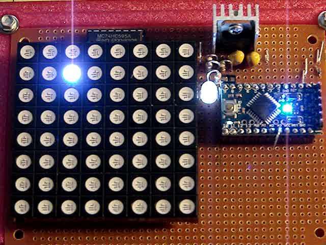
The lamp test ends with all the LEDs turned off, but having the array gradually fill with light looked odd.
After some tinkering, I added the GeigerTicked conditional to handshake with the Geiger pulse interrupt handler, thus producing a nice random time at the end of the loop. Feed that mostly random time into the hash function, use the hash as the random number seed, then set all the LEDs using random(2) function calls:
	randomSeed(jenkins_one_at_a_time_hash((char *)GeigerTime,4));

	for (byte Row=0; Row<NUMROWS; Row++) {
		for (byte Col=0; Col<NUMCOLS; Col++) {		// Col runs backwards, but we don't care
			LEDs[Row].ColR |= random(2) << Col;
			LEDs[Row].ColG |= random(2) << Col;
			LEDs[Row].ColB |= random(2) << Col;
		}
		UpdateLEDs(Row);
	}

	GeigerTicks = 0;				// reset counter
	GeigerTicked = false;			// resume capture
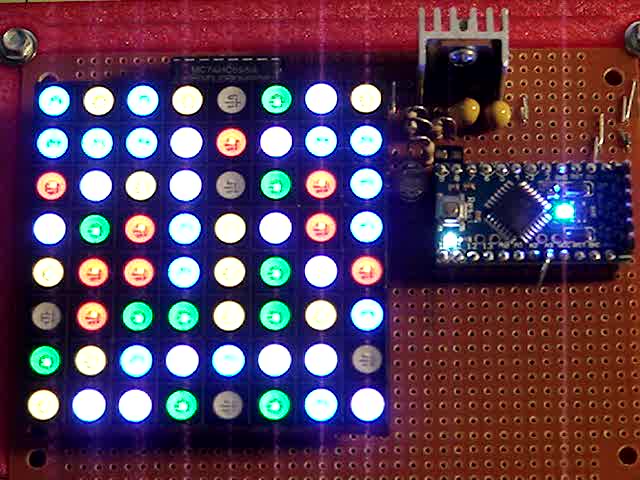
Which produced a more-or-less random fill that looked better:
Random Preload – bright
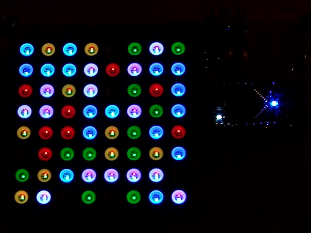
Underexposed to reduce the burnout (after a few Geiger events):
Random Preload – dim
There should be about eight of each color and, hey, it’s close enough.
In need of a quick-and-easy way to generate interesting data that would make an LED array do something and, what with radioactivity being the canonical source for random numbers, an ancient Aware Electronics RM-60 (*) emerged from the heap. The manual will get you up to speed on radiation detection, if you can read past the DOS-era program description.
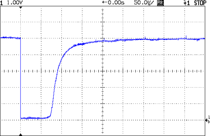
It produces a 100 µs (-ish) pulse for each detection:
Aware RM-60 Geiger Pulse
The minimum period seems to be around 500 µs, but I lack a sufficiently fierce radioactive source to verify that in any finite amount of time.
Seeing as how all we need is a little randomness, measuring the time when a pulse occurs will suffice; we’re not talking hardcore crypto.
With the pulse arriving on the Arduino D2 input, define an interrupt handler that sets a flag, bumps a counter, and records the current time in microseconds:
void GeigerHandler(void) {
	if (!GeigerTicked) {				// stop recording until loop() extracts the data
		GeigerTicked = true;
		GeigerTicks++;
		GeigerTime = micros();
	}
}
Define D2 as an input, turn on the pullup, and trigger that handler on the falling edge of the pulse:
pinMode(PIN_GEIGER,INPUT_PULLUP);	// RM-60 has its own pullup, but add this one, too

attachInterrupt((PIN_GEIGER - 2),GeigerHandler,FALLING);
Because an absolute timestamp of each event will produce an obviously non-random sequence of monotonically increasing numbers, I ran each four byte timestamp through a simple hash function to whiten the noise:
Then the only thing left to do is spin around the loop() while waiting for a particle to arrive:
	if (GeigerTicked) {
		digitalWrite(PIN_HEARTBEAT,HIGH);				// show a blip
		analogWrite(PIN_DIMMING,LEDS_OFF);				// turn off LED array to prevent bright glitch

		Hash = jenkins_one_at_a_time_hash((char *)&GeigerTime,4);	// whiten the noise

		GeigerTicked = false;							// flag interrupt handler to resume recording
//			printf("%9ld %08lx %08lx ",GeigerTicks,GeigerTime,Hash);
		SetLED(Hash);
	}
(*) Circuit Cellar readers of long memory will recognize the RM-60 as the McGuffin for the Radioactive Randoms column in 1990 that explained features of interrupt-driven code in a Micromint BASIC-52 board. Decades later, the hardware & software served as Prior Art in a patent suit that forced me to write some Rules of Engagement. Selah.
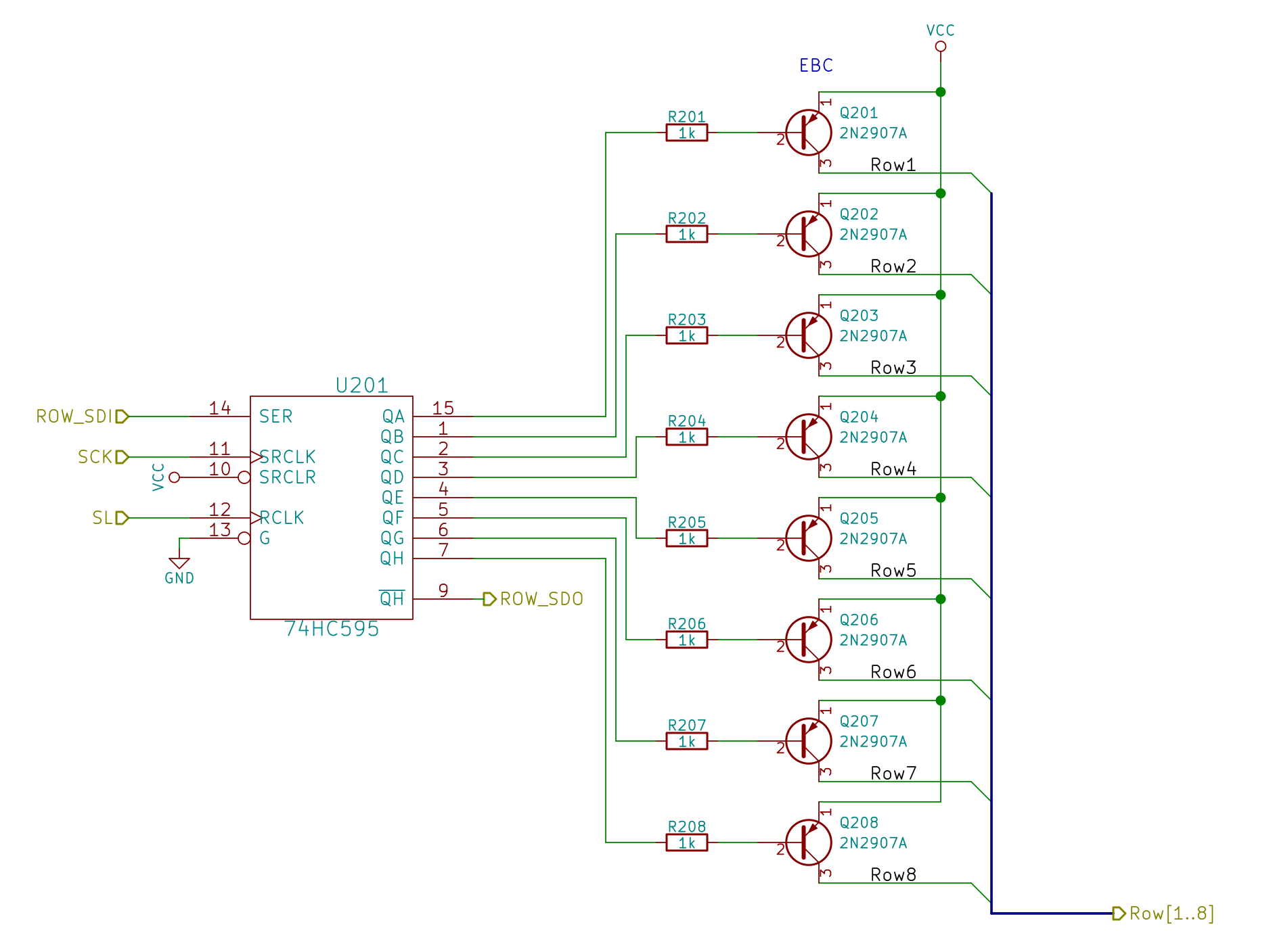
The LED panel requires multiplexing: turning on one of the PNP transistors activates a single row, with the column shift registers determining which of the 24 LEDs in that row will light up. Because each row remains lit until the next one appears, it will be about 1/8 as bright as a “DC” display.
Random LED Dots – Row Drivers
Although the hardware allows turning on more than one row at a time, that’s a Bad Idea that will produce Bad Results: the column shift registers can’t sink that much current.
Bitmapping the whole array requires 8 x 4 = 32 bytes, which isn’t all that much for an ATmega328 with 2 KB of RAM and nothing else on its mind:
I decided to use positive logic in the array, then invert the bits on their way to the SPI hardware.
Setting a single LED to a color value requires chopping the color into its three component RGB bits, clearing the appropriate bits in the array, then stuffing the new ones in place:
The Value comes from a radiation-based random number source that produces 32 bits at a time. I suppose you could just slap 24 of the bits into the column values in a row selected by three other bits to update All! The! Dots! in one shot, but it seemed less exciting to update a single LED on each iteration; the update timing is also an interesting random quantity.
Each iteration of the main() loop squirts the (inverted) bits for a single row through the SPI hardware:
void WaitSPIF(void) {
	while (! (SPSR & (1 << SPIF))) {
//		TogglePin(PIN_HEARTBEAT);
		continue;
	}
}

byte SendRecSPI(byte Dbyte) {			// send one byte, get another in exchange
	SPDR = Dbyte;
	WaitSPIF();
	return SPDR;						// SPIF will be cleared
}

void UpdateLEDs(byte i) {

	SendRecSPI(~LEDs[i].ColB);			// low-active outputs
	SendRecSPI(~LEDs[i].ColG);
	SendRecSPI(~LEDs[i].ColR);
	SendRecSPI(~LEDs[i].Row);

	analogWrite(PIN_DIMMING,LEDS_OFF);	// turn off LED to quench current
	PulsePin(PIN_LATCH);				// make new shift reg contents visible
	analogWrite(PIN_DIMMING,LEDS_ON);

}
I don’t do anything with the returned bytes, but perhaps that’ll be a way to get some random numbers into the program later on.
It turned out that all the green LEDs in a column with one lit LED glowed very, very dimly if they weren’t turned off for a while; a few microseconds while pulsing the shift register parallel load clock seems to work reasonably well. I think the glow comes from microamp-level leakage current through the turned-off PNP transistors, but I haven’t tracked it down yet.
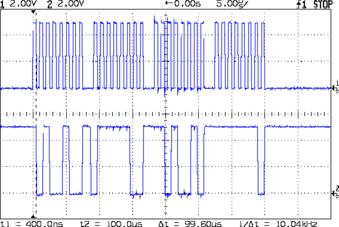
The hardware SPI runs at 1 µs/bit with short gaps while cuing up the next byte:
Hardware SPI – SCLK SDAT
The last byte out (over on the right) contains the row select bits, of which only one can be active (low) at a time.
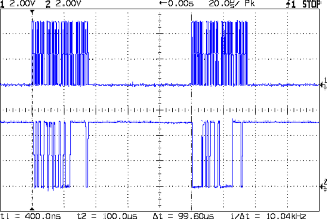
The main() loop doesn’t have much else to do, so the rows refresh at 10 kHz:
Hardward SPI – Refresh
That means the LEDs in each row are active for only 100 µs and, given a whole-panel refresh of 1250 kHz (!), the LEDs appear to shimmer slightly during eye saccades. It’s a much nicer effect than the flicker produced by slower refresh intervals and has much the same eye-magnet attraction as coherent laser light.
The code emits a scope sync pulse just after Row 7 goes out the door, so you can get ready for the next iteration:
Using SPI for the outputs means the Arduino Pro Mini doesn’t need all that many other connections:
Random LED Dots – Power – Arduino Pro Mini
You should use a regulated 5 V DC supply and discard the regulator; I was planning something else that didn’t come to pass. Backfeeding the Pro Mini’s regulator seems to be No Problem. Do not attempt to feed the LEDs from the Pro Mini’s regulator, OK?
The white heartbeat LED replaces the standard Arduino D13 LED that the hardware uses for the SPI clock output.
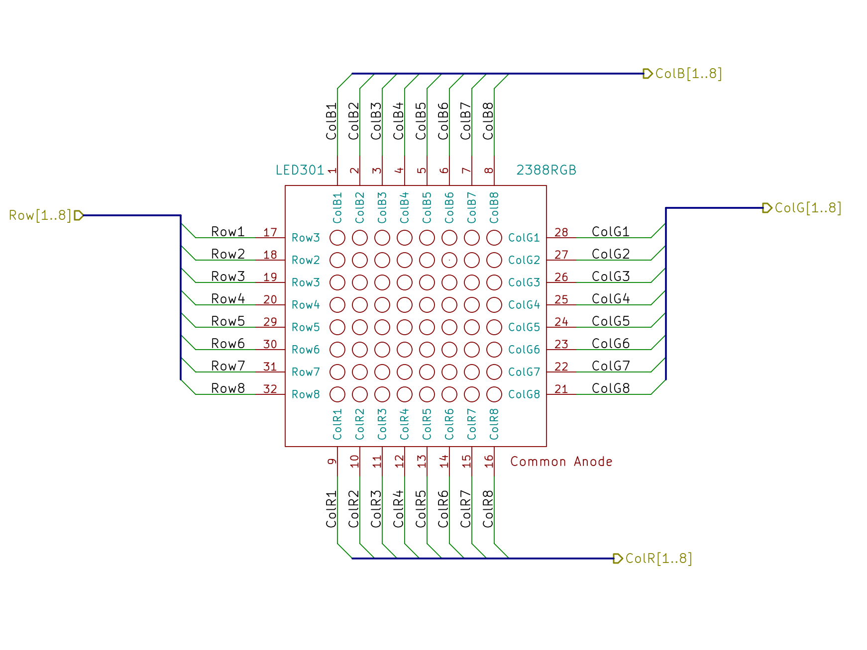
The LED panel has common-anode rows and separate RGB columns. This part layout makes it look far more symmetrical than it should be, but it’d be a page wide with all 24 column lines along the bottom, where they should be:
Random LED Dots – 2388RGB LED panel
The row drivers use 2N2907A PNP transistors from my lifetime supply:
Random LED Dots – Row Drivers
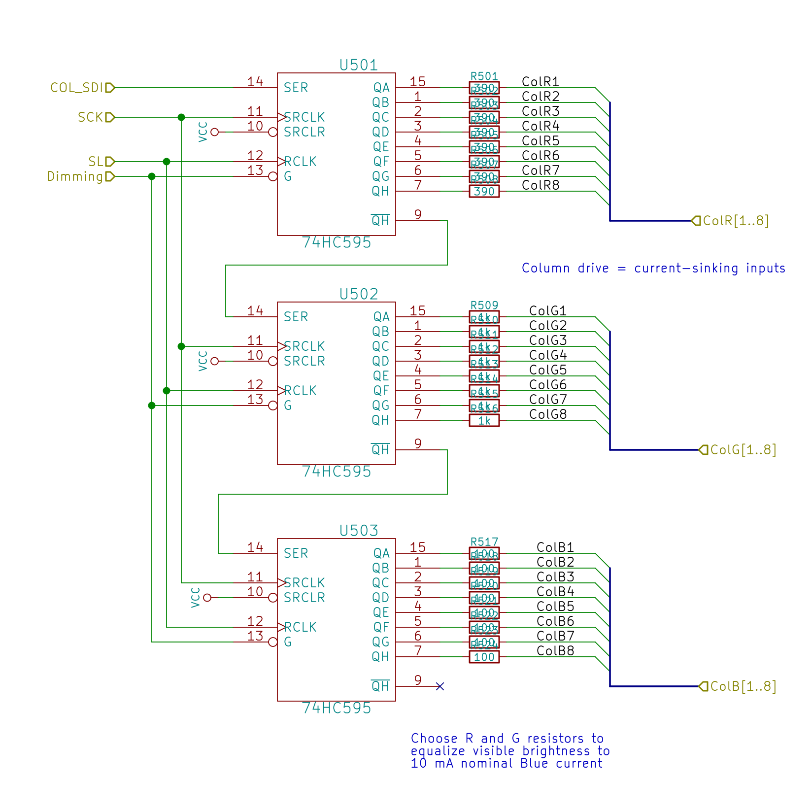
The column drivers abuse 74HC595 shift registers (because SPI) as current sinks:
Random LED Dots – RGB Column Drivers
This thing will become a desk toy, so the LEDs need be only bright enough for direct viewing at short range. The panel (or some similar panel) can run at 50 mA continuous current, enough to put spots on your retinas, so throttling it back seemed prudent.
In any event, the shift registers can’t handle all that much current, so I set the blue LEDs at a nominal 10 mA and picked the other ballast resistors to produce more-or-less the same brightness. In round numbers, the red LEDs run at 5 mA and the green at 3 mA:
Random LED Dots – LED colors – detail
An all-on blue row will dump 80 mA (more or less) into a single 74HC595, which seems to be within its specs, and the registers for the other colors will loaf along at a few tens of mA. In real life, you’d use actual LED drivers, perhaps with PWM intensity control, and be done with it. Here, I’m going cheap and easy with eight colors, one of which is off.
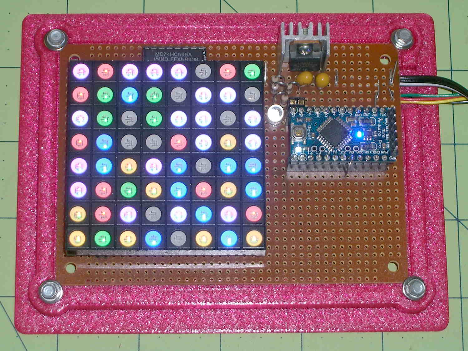
The LED chips sit at the bottom of a white funnel (OK, a frustum) under a clear flat lens, with the red and blue chips washing the closest sides. All-on white sites (R+G+B, lower left) came out slightly blue overall, with a reddish tinge toward the top. Magenta sites (R+B, upper left) seem slightly more reddish than they should be. Cyan sites (G+B, middle right) have too little green.
The granularity of SMD resistor values in my heap limits the amount of fine tuning; I am so not going to stack SMD resistors for color adjustment.
None of that matters in this application, of course.
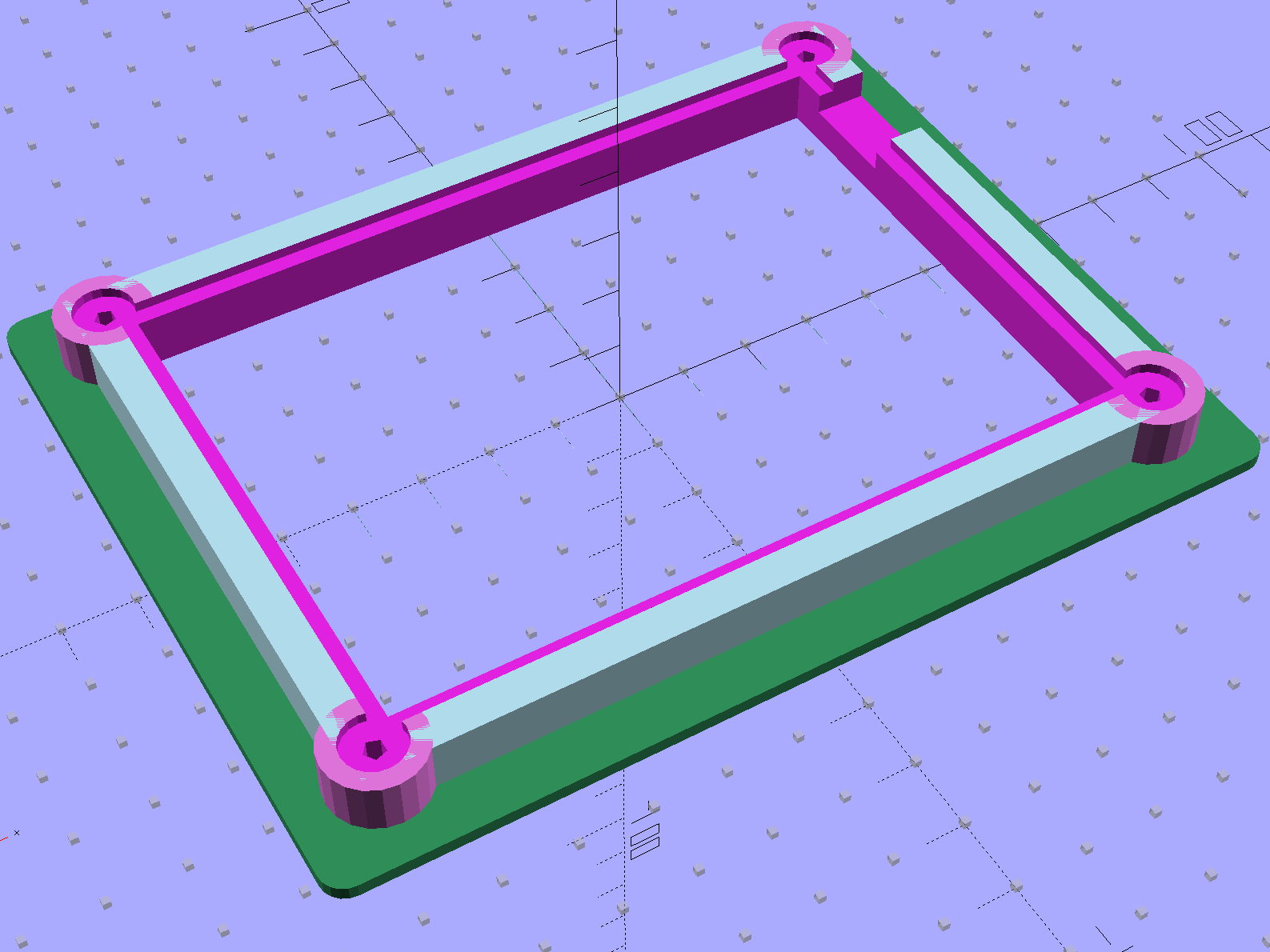
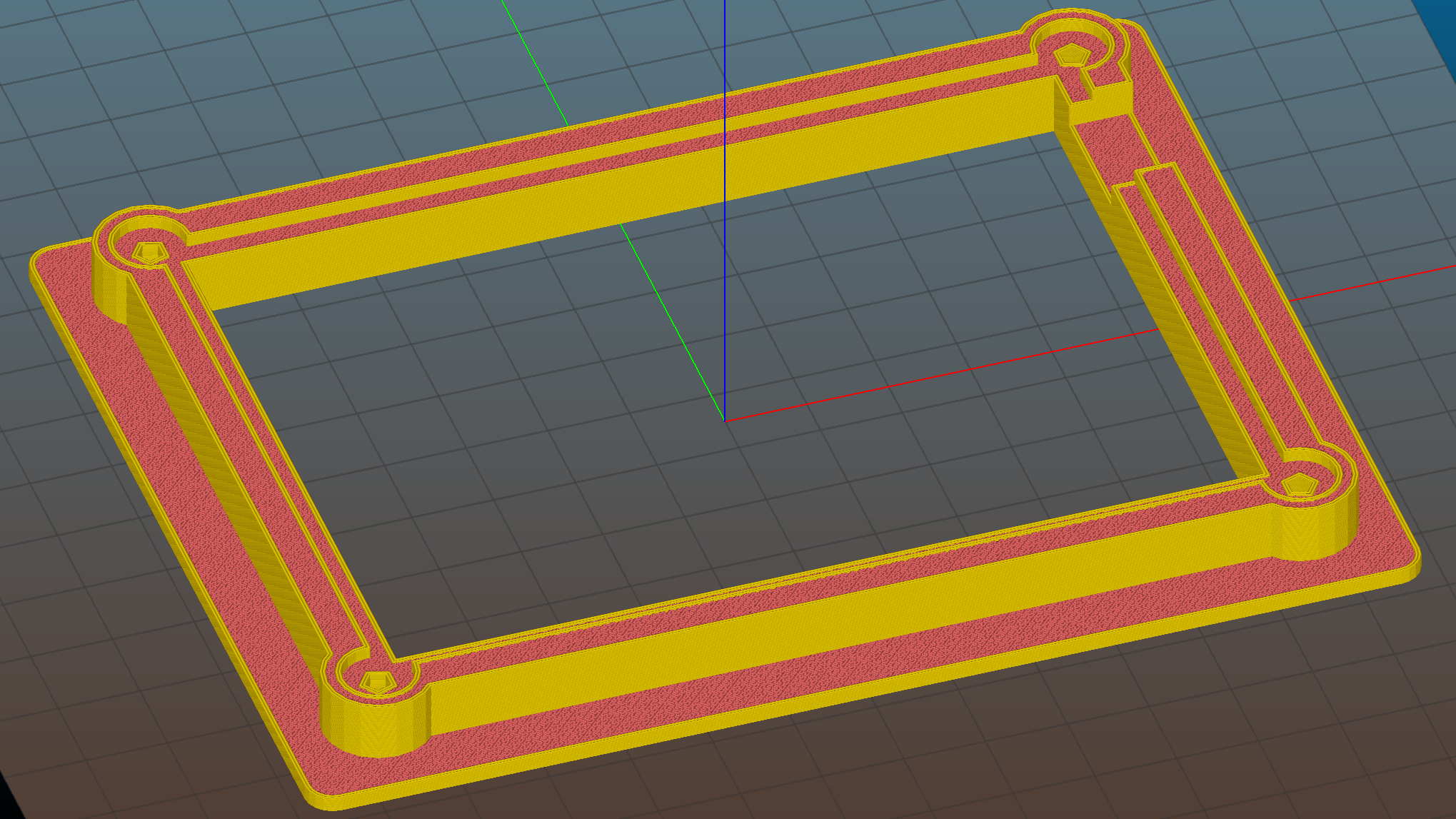
Quite some time ago, Sophi gave me a common-anode RGB LED panel and told me to make something of it. In a spate of desk-clearing, I hammered out a quick-and-dirty multiplexed display from found materials: 2N2907 transistors as row source drivers and 74HC595 shift registers abused as column sink drivers, plus the obligatory Arduino Pro Mini and 3D printed holder:
Random LED Dots – circuit board
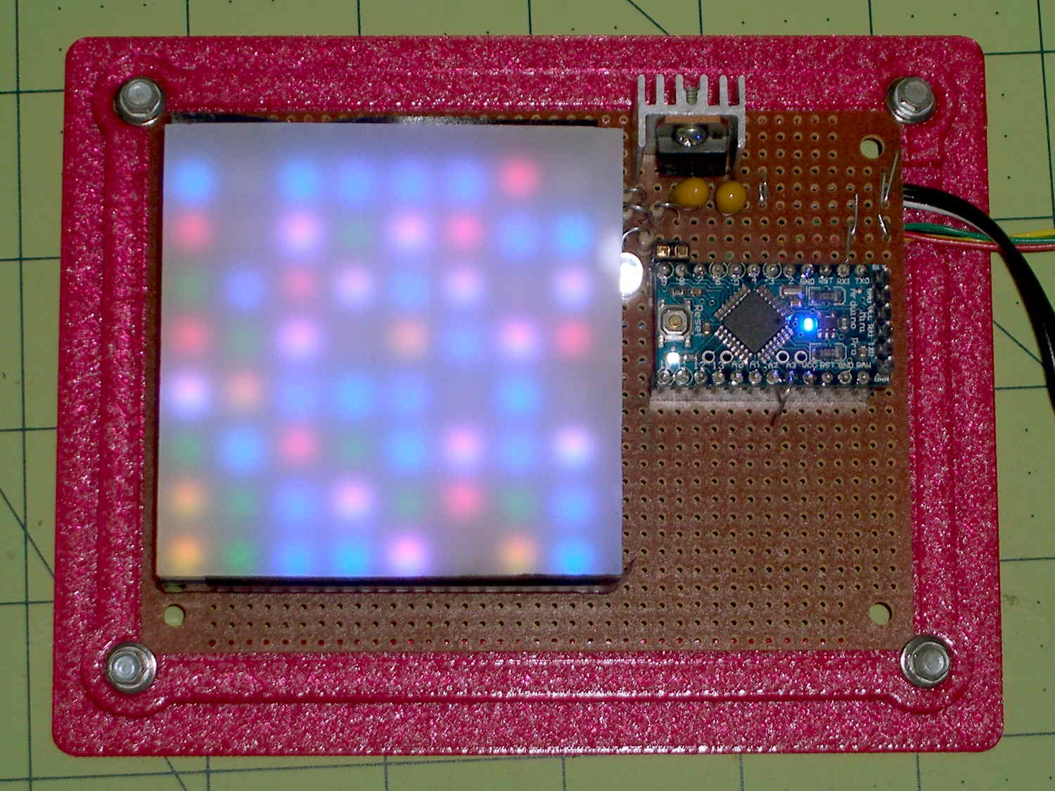
A sheet of milk-white acrylic diffuses the glittery LED dots into pastel disks. I think it might look better without the diffuser; it certainly has a harder-edged tech look:
Random LED Dots – overview – no diffuser
A neutral-density filter would boost the contrast without hiding any of the details.
It obviously needs an enclosure, but, around here, that’s in the nature of fine tuning.
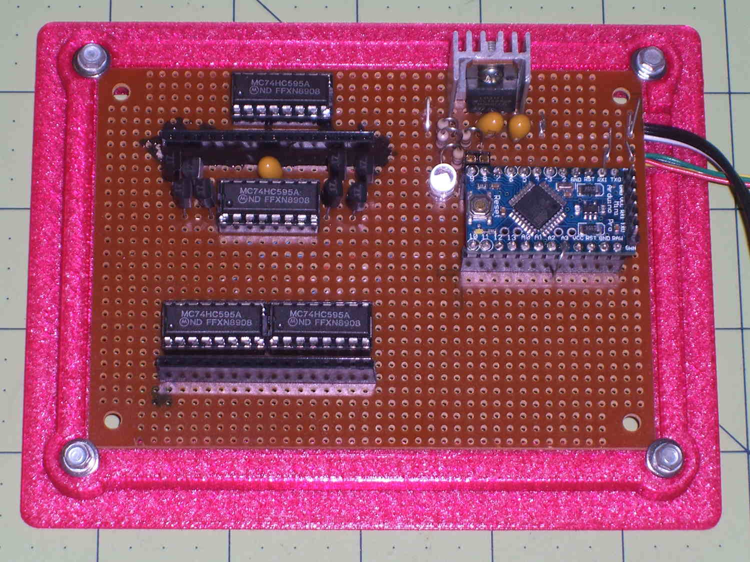
The transistors and shift registers cower under the panel:
Random LED Dots – circuit layout – top
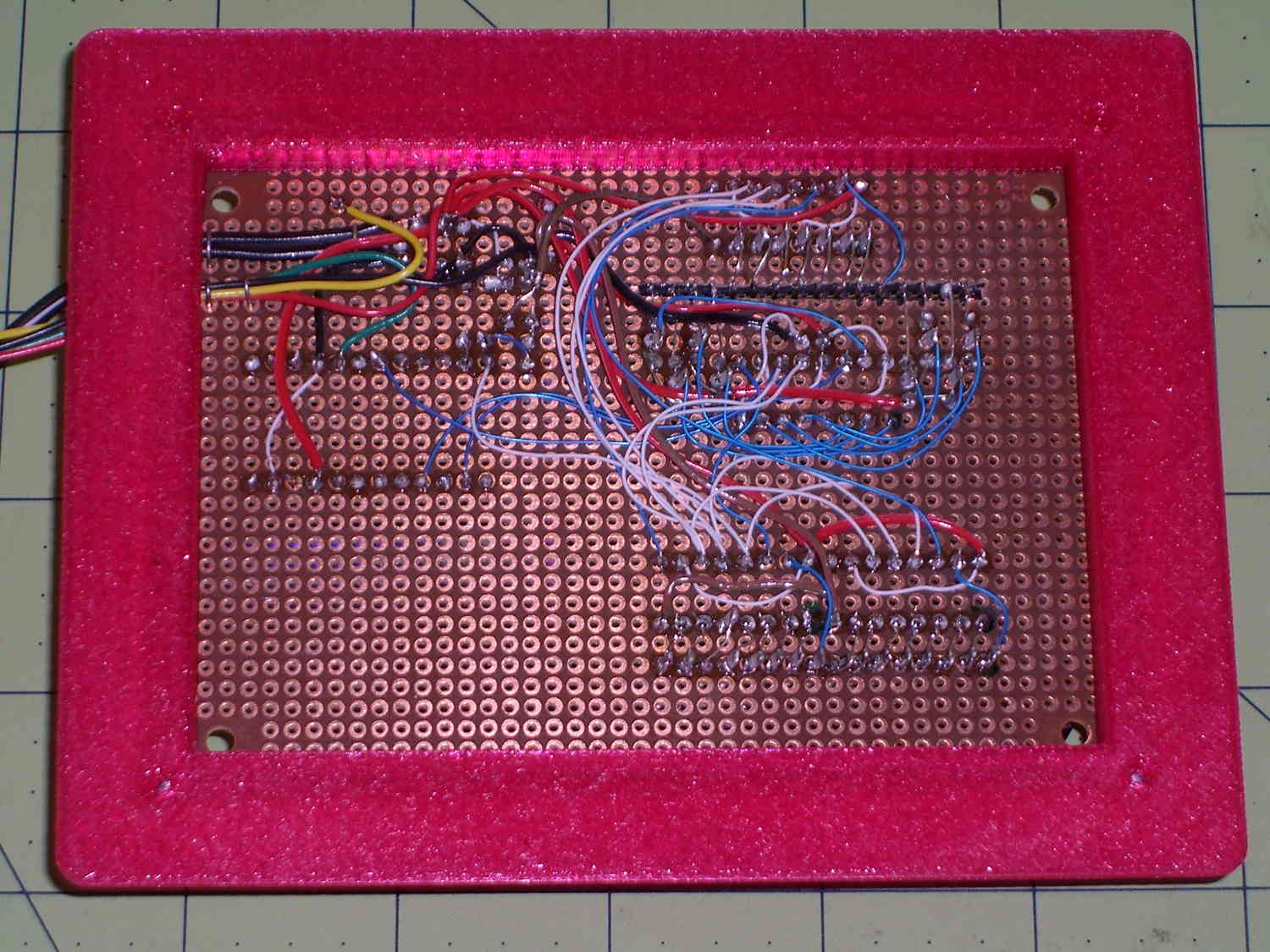
The bottom view exposes the hand wiring, plus the slot required to adapt the LED panel’s non-100-mil layout to the protoboard’s holes. I chopped out the slot with a Dremel saw, attached socket strips to the panel, and epoxied the floating strip in place:
Random LED Dots – circuit layout – bottom
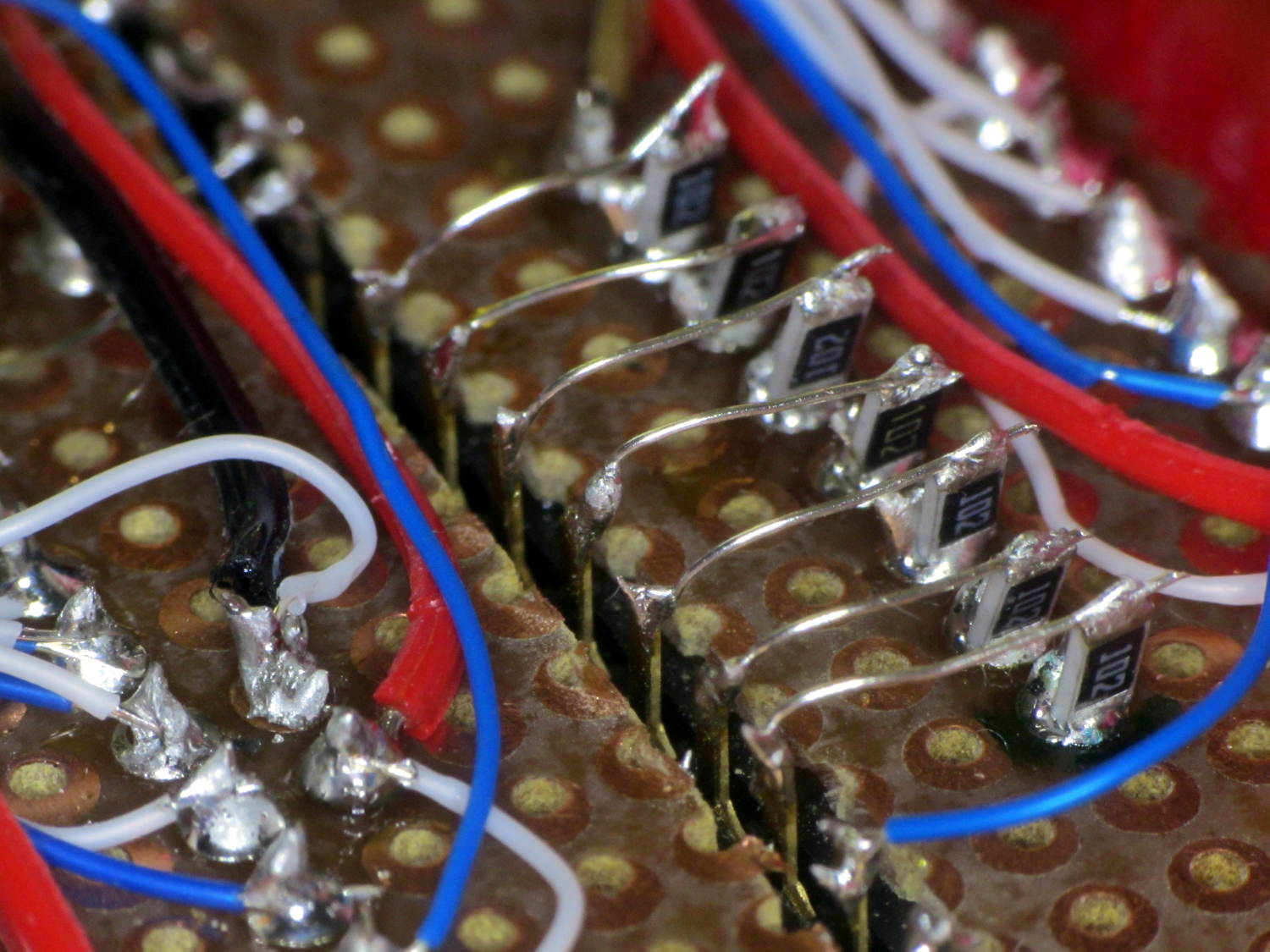
The prospect of wiring 32 discrete resistors filled me with dread, so I just tombstoned SMD resistors onto the protoboard solder blobs:
Random LED Dots – circuit layout – RB SMD resistors
The slot required slightly longer bridge wires:
Random LED Dots – circuit layout – G SMD resistors
The layout, such as it is, made those short, direct wires possible. A PCB with SMD chips would be even better.
MHVLUG meetings end around 8 pm and, depending on this-and-that, the bell atop Old Main on the Vassar College campus will be tolling the hour as we emerge. Here’s a scene-setting photo from Wikimedia, taken from about where I parked the car:
Vassar College Old Main Building
Although the bell didn’t have its usual steady rhythm after the most recent meeting, I didn’t expect this:
Bell Ringers atop Vassar Old Main
The tree grows in the near foreground, not over Old Main.
Two of them realized the risk of permanent hearing damage, but do you see the real hazard?