Ed Nisley's Blog: Shop notes, electronics, firmware, machinery, 3D printing, laser cuttery, and curiosities. Contents: 100% human thinking, 0% AI slop.
From a datalogger hanging on a string in the well pit, about three feet underground, in December:
Well Pit – 2014-12 – min size
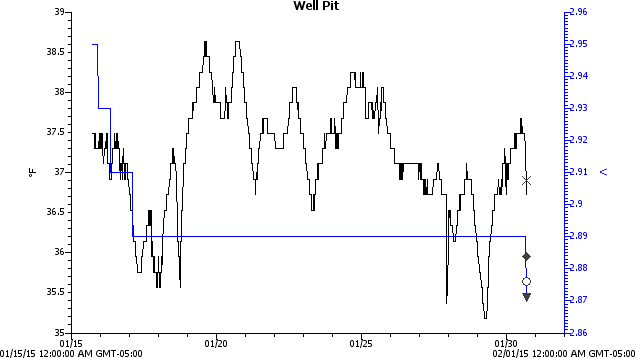
The temperatures continue downward in January:
Well Pit – 2015-01 – min size
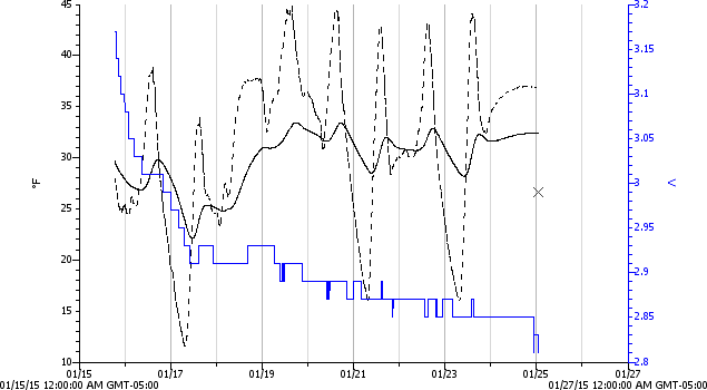
The corresponding attic air temperature record for January ends early:
Attic – Insulated Box – Maxell battery failure
When the air temperature dropped to +11 °F in the early hours of 17 January 2015, the well pit hit 35.5 °F. It was just over 35 °F in the wee hours of 29 January 2015, but the attic logger gave up as the battery voltage declined to 2.8 V.
Evidently, the new Maxell CR2032 lithium cells don’t do well in extreme cold. They’re rated to -20 °C = -4 °F, but that spec applies for a very low load that surely doesn’t include blinking a red LED.
I’ll take a look at that logger in a few days, then hack a pair of AA cells on the back if it’s dead again. Alkaline cells aren’t very good in cold weather, either, but they may have a better minimum voltage.
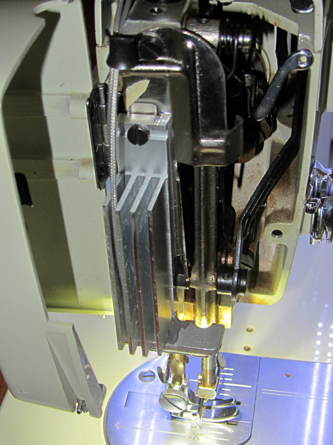
The Kenmore 158 sewing machine crash test dummy has plenty of light:
Kenmore 158 LED Lighting – first light
Well, as long as you don’t mind the clashing color balance. The needle LEDs turned out warmer than I expected, but Mary says she can cope. I should build a set of warm-white LED strips when it’s time to refit her real sewing machine and add another boost supply to drive them at their rated current.
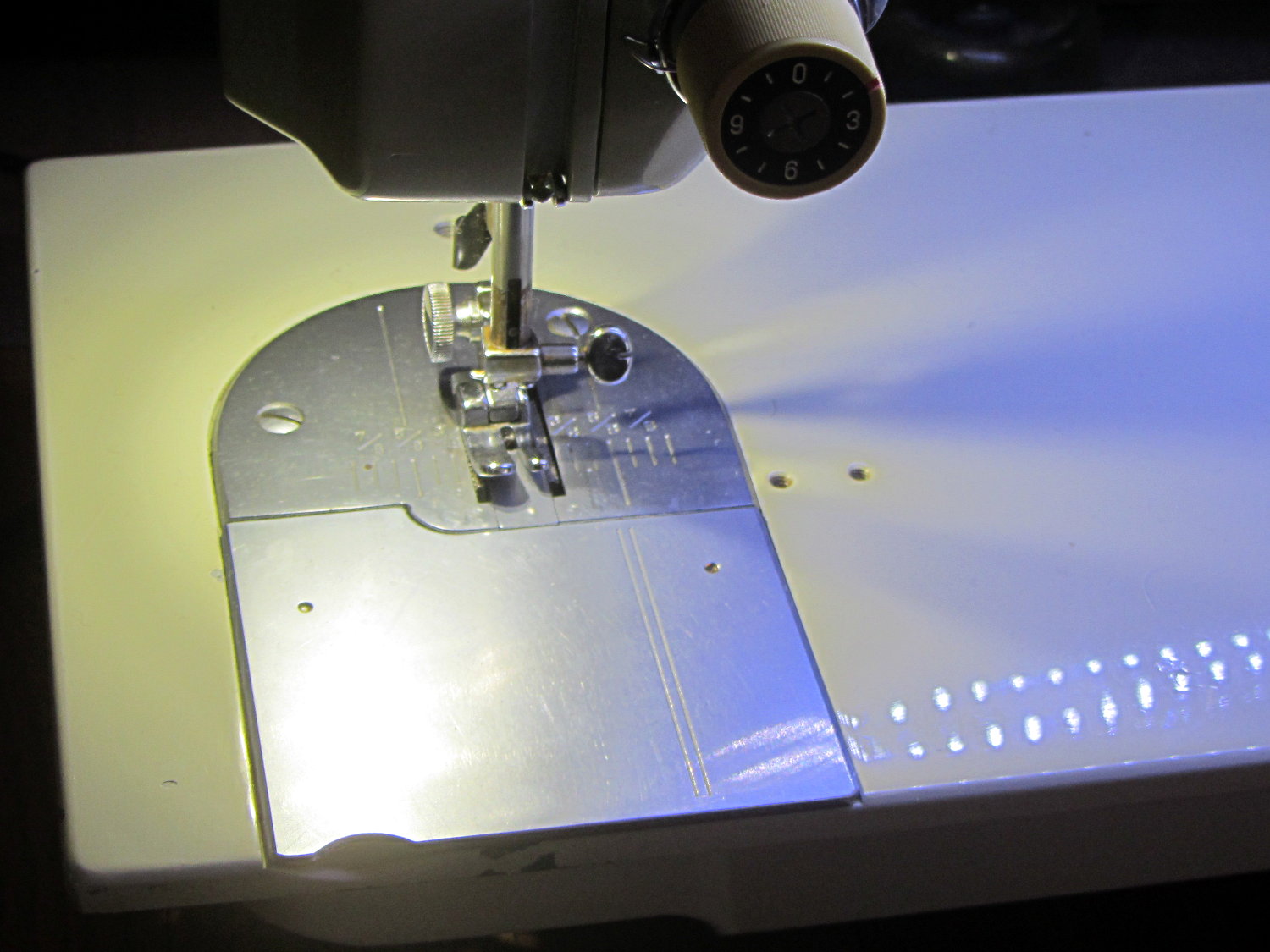
Much to our relief, the two LEDs at the needle don’t cast offensively dark shadows:
The DC-DC boost power supply for the LED needle lights has four mounting holes, two completely blocked by the heatsink and the others against components with no clearance for screw heads, soooo …
3D printing to the rescue:
Boost converter – installed
Now that the hulking ET227 operates in saturation mode, I removed the blower to make room for the power supply. Two strips of double-stick foam tape fasten the holder to the removable tray inside the Dell GX270’s case.
It’s basically a rounded slab with recesses for the PCB and clearance for solder-side components:
Boost converter mount – as printed
The solid model shows the screw holes sitting just about tangent to the PCB recess:
XW029 Booster PCB Mount
That’s using the new OpenSCAD with length scales along each axis; they won’t quite replace my layout grid over the XY plane, but they certainly don’t require as much computation.
I knew my lifetime supply of self-tapping hex head 4-40 screws would come in handy for something:
Boost converter in mount
The program needs to know the PCB dimensions and how much clearance you want for the stuff hanging off the bottom:
PCBoard = [66,35,IntegerMultiple(1.8,ThreadThick)];

BottomParts = [[1.5,-1.0,0,0],	// xyz offset of part envelope
				[60.0,37.0,IntegerMultiple(3.0,ThreadThick)]];	// xyz envelope size (z should be generous)
That’s good enough for my simple needs.
The hole locations form a list-of-vectors that the code iterates through:
That’s the first occasion I’ve had to try iterating a list and It Just Worked; I must break the index habit. The newest OpenSCAD version has Python-ish list comprehensions which ought to come in handy for something.
The “Z coordinate” of each hole position gives its rotation, so I could snuggle them up a bit closer to the edge by forcing the proper polygon orientation. The square roots in the second two holes make them tangent to the corners of the PCB, rather than the sides, which wasn’t true for the first picture. Fortunately, the washer head of those screws turned out to be just big enough to capture the PCB anyway.
Given the data structures defining the buttons, this code in the main loop() detects a touch, identifies the corresponding button, and does what’s needed:
if (CleanTouch(&pt)) {
	BID = FindHit(pt);
	if (BID) {
		HitButton(BID);
	}
	while(ts.touched())				// stall waiting for release
		ts.getPoint();
}
The CleanTouch() function handles touch detection, cleanup, and rotation, delivering a coordinate that matches one of the LCD pixels. Given that you’re using a fingertip, errors caused by poor calibration or nonlinearities Just Don’t Matter.
This function matches that coordinate against the target region of each button, draws a white rectangle on the first matching button, and returns that button ID:
byte FindHit(TS_Point hit) {

byte i;
TS_Point ul,lr;

#define MARGIN 12

//	printf("Hit test: (%d,%d)\r\n",hit.x,hit.y);

	for (i=0; i<NumButtons ; i++) {
		ul.x = Buttons[i].ulX + Buttons[i].szX/MARGIN;
		ul.y = Buttons[i].ulY + Buttons[i].szY/MARGIN;
		lr.x = Buttons[i].ulX + ((MARGIN - 1)*Buttons[i].szX)/MARGIN;
		lr.y = Buttons[i].ulY + ((MARGIN - 1)*Buttons[i].szY)/MARGIN;
//		printf(" i: %d BID: %d S: %d ul=(%d,%d) sz=(%d,%d)\r\n",
//			   i,Buttons[i].ID,Buttons[i].Status,ul.x,ul.y,lr.x,lr.y);
		if ((hit.x >= ul.x && hit.x < lr.x) &&
			(hit.y >= ul.y && hit.y <= lr.y)) {
			// should test for being disabled and discard hit
//			printf(" Hit i: %d ",i);
			break;
		}
	}

	if (i < NumButtons) {
		tft.drawRect(ul.x,ul.y,lr.x-ul.x,lr.y-ul.y,ILI9341_WHITE);
		return Buttons[i].ID;
	}
	else {
		printf(" No hit!\r\n");
		return 0;
	}

}
You can enable as much debugging as you need by fiddling with the commented-out lines.
After some empirical fiddling, a non-sensitive margin of 1/12 the button size helped prevent bogus hits. There’s no real need to draw the target rectangle, other than for debugging:
Kenmore 158 UI buttons – hit target
The target shows the button graphics aren’t quite centered, because that’s how the ImageMagick script placed them while generating the shadow effect, but it still works surprisingly well. The next version of the buttons will center the graphics, specifically so I don’t have to explain what’s going on.
Because the margin is 1/12 the size of the button, it rounds off to zero for the tiny button in the upper right corner, so that the touch target includes the entire graphic.
The return value will be zero if the touch missed all the buttons, which is why a button ID can’t be zero.
Given the button ID, this function un-pushes the other button(s) in its radio button group, then pushes the new button:
byte HitButton(byte BID) {

byte i,BX;
byte Group;

	if (!BID)											// not a valid ID
		return 0;

	BX = FindButtonIndex(BID);
	if (BX == NumButtons)								// no button for that ID
		return 0;

	Group = Buttons[BX].Group;

//	printf(" Press %d X: %d G: %d\r\n",BID,BX,Group);

// If in button group, un-push other buttons

	if (Group) {
		for (i=0; i<NumButtons; i++) {
			if ((Group == Buttons[i].Group) && (BT_DOWN == Buttons[i].Status)) {
				if (i == BX) {							// it's already down, fake going up
					Buttons[i].Status = BT_UP;
				}
				else {									// un-push other down button(s)
//					printf(" unpress %d X: %d \r\n",Buttons[i].ID);
					Buttons[i].pAction(Buttons[i].ID);
				}
			}
		}
	}

	Buttons[BX].pAction(BID);

	return 1;
}
The ID validation shouldn’t be necessary, but you know how things go. A few messages in there would help debugging.
The default button action routine that I use for all the buttons just toggles the button’s Status and draws the new button graphic:
void DefaultAction(byte BID) {

byte i,BX;

	if (!BID) {											// not a valid ID
		printf("** Button ID zero in DefaultAction\r\n");
		return;
	}

	BX = FindButtonIndex(BID);
	if (BX == NumButtons) {								// no button for that ID
		printf("** No table entry for ID: %d\r\n",BID);
		return;
	}

	Buttons[BX].Status = (Buttons[BX].Status == BT_DOWN) ? BT_UP : BT_DOWN;

	printf("Button %d hit, now %d\r\n",BID,Buttons[BX].Status);
	DrawButton(BID,Buttons[BX].Status);

}
The little color indicator button has a slightly different routine to maintain a simple counter stepping through all ten resistor color codes in sequence:
void CountColor(byte BID) {

byte i,BX;
static byte Count = 0;

	if (!BID) {											// not a valid ID
		printf("** Zero button ID\r\n");
		return;
	}

	BX = FindButtonIndex(BID);
	if (BX == NumButtons) {								// no button for that ID
		printf("** No entry for ID: %d\r\n",BID);
		return;
	}

	Buttons[BX].Status = BT_DOWN;						// this is always pressed

	Count = (Count < 9) ? ++Count : 0;					// bump counter & wrap

//	printf("Indicator %d hit, now %d\r\n",BID,Count);
	DrawButton(BID,Count);

}
The indicator “button” doesn’t go up when pressed and its function controls what’s displayed.
I think the button action function should have an additional parameter giving the next Status value, so that it knows what’s going on, thus eliminating the need to pre-push & redraw buttons in HitButton(), which really shouldn’t peer inside the button data.
It needs more work and will definitely change, but this gets things started.
The trouble with grafting a fancy LCD on an 8 bit microcontroller like an Arduino is that there’s not enough internal storage for button images and barely enough I/O bandwidth to shuffle bitmap files from the SD card to the display. Nevertheless, that seems to be the least awful way of building a serviceable UI that doesn’t involve drilling holes for actual switches, indicators, and ugly 2×20 character LCD panels.
Rather than hardcoding the graphics into the Arduino program, though, it makes sense to build a slightly more general framework to handle button images and overall UI design, more-or-less independently of the actual program. I haven’t been able to find anything that does what I need, without doing a whole lot more, sooooo here’s a quick-and-dirty button framework.
Calling it a framework might be overstating the case: it’s just a data structure and some functions. It really should be a separate library, but …
After considerable discussion with the user community, the first UI can control just three functions:
Needle stop position: up, down, don’t care
Operating mode: follow pedal position, triggered single-step, normal run
Speed: slow, fast, ultra-fast
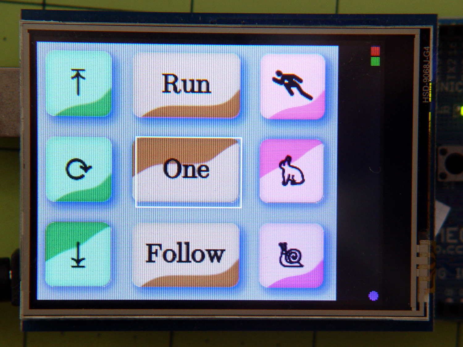
That boils down into a simple nine-button display, plus a tiny tenth button (in brown that looks red) at the top right:
The two upper button are “up”, with light glinting from upward-bulging domes
The lower button is “down”, with light glinting from its pushed-in dome
Frankly, that works poorly for me and the entire user community. The whole point of this framework is to let me re-skin the UI without re-hacking the underlying code; the buttons aren’t the limiting factor right now.
Anyhow.
The three buttons in each column are mutually exclusive radio buttons, but singleton checkbox buttons for firmware switches / modes would also be helpful, so there’s motivation to be a bit more general.
A struct defines each button:
enum bstatus_t {BT_DISABLED,BT_UP,BT_DOWN};

typedef void (*pBtnFn)(byte BID);		// button action function called when hit

struct button_t {
	byte ID;					// button identifier, 0 unused
	byte Group;					// radio button group, 0 for none
	byte Status;				// button status
	word ulX,ulY;				// origin: upper left
	word szX,szY;				// button image size
	pBtnFn pAction;				// button function
	char NameStem[9];			// button BMP file name - stem only
};
The ID uniquely identifies each button in the rest of the code. That should be an enum, but for now I’m using an unsigned integer.
The Group integer will be zero for singleton buttons and a unique nonzero value for each radio button group. Only one button in each Group can be pressed at a time.
The Status indicates whether the button can be pushed and, if so, whether it’s up or down. Right now, the framework doesn’t handle disabled buttons at all.
The next four entries define the button’s position and size.
The pAction entry contains a pointer to the function that handles the button’s operation. It gets invoked whenever the touch screen registers a hit over the button, with an ID parameter identifying the button so you can use a single function for the entire group. I think it’ll eventually get another parameter indicating the desired Status, but it’s still early.
The NameStem string holds the first part of the file name on the SD card. The framework prefixes the stem with a default directory (“/UserIntf/”), suffixes it with the Status value (an ASCII digit ‘0’ through ‘9’), tacks on the extension (“.bmp”), and comes up with the complete file name.
An array of those structs defines the entire display:
Those values produce the screen shown in the picture. The first three buttons should be members of radio button group 1, but they’re singletons here to let me test that path.
Contrary to what you see, the button ID values need not be in ascending order, consecutive, or even continuous. The IDs identify a specific button, so as long as they’re a unique number in the range 1 through 255, that’s good enough. Yes, I faced down a brutal wrong-variable error and then fixed a picket-fence error.
The file name stems each refer to groups of BMP files on the SD card. For example, NdUp (“Needle stop up”) corresponds to the three files NdUp0.bmp, NdUp1.bmp, and NdUp2.bmp, with contents corresponding to the bstatus_t enumeration.
The constant elements of that array should come from a configuration file on the SD card: wrap a checksum around it, stuff it in EEPROM, and then verify it on subsequent runs. A corresponding array in RAM should contain only the Status values, with the array index extracted from the EEPROM data. That would yank a huge block of constants out of the all-too-crowded RAM address space and, even better, prevents problems from overwritten values; a trashed function pointer causes no end of debugging fun.
A more complex UI would have several such arrays, each describing a separate panel of buttons. There’s no provision for that right now.
For a pure indicator, it’d be easier to slap a spot on the screen with the Adafruit GFX library’sfillRect() function. If you’re setting up a generic button handler, then button bitmap images make more sense.