Ed Nisley's Blog: Shop notes, electronics, firmware, machinery, 3D printing, laser cuttery, and curiosities. Contents: 100% human thinking, 0% AI slop.
I embossed the studs into a pad of Geek Scratch Paper, eyeballed the stud-to-stud spacing from a cheap ruler, back-calculated the BCD, rounded it from 2.742 to the obvious 2.75, then fed that into the first BCD calculator that appeared in the obvious search.
The can is just over 3.5 inch OD and stands 1.5 inch tall.
The can will run at +24 V in relation to the rest of the circuitry, so the studs must be insulated from the PCB’s copper pours. That, most likely, will require some 3D printed doodads.
The circuitry must live inside a grounded metallic can that excludes random electric fields. Somewhere in the pile, I have a few sheets of Mu-metal that, while grossly overqualified for the task (even without heat treatment), should solder up nicely…
Armed with bags of electronic parts and boxes of meters, I’ll be helping folks at the CNC Workshop understand the electrical limitations of the Arduino microcontrollers they’re building into projects.
That might be rosin left over from soldering, but you’d think they would have rinsed it off to reduce the leakage. Some cleaning will be in order.
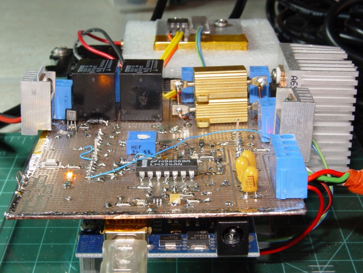
A picture in The Fine Manual for the CD-V-710 Model 5 Radiation Survey Meter showed that the circuit board used point-to-point wiring, with the range switch soldered directly to that bent metal contact:
Another page gave some useful values and a simplified schematic:
Victoreen CD-V-710 Model 5 Manual – Page 5
Never fear, the manual also has the full schematic; they don’t write manuals like that any more.
The chamber bias voltage was +22.5, from one carbon-zinc battery available back in the 1950s. You can still get 22.5 V batteries at about ten bucks a pop, but 24 V from a pair of cheap & readily available 12 V A23 alkaline batteries should be close enough. There’s no current drain, so the batteries should last their entire shelf life.
The “HI-MEG” resistor represents a trio of glass-body resistors selected by the range switch:
R5 = 100 GΩ → 0.5 R/h
R6 = 10 GΩ→ 5 R/h
R7 = 1 GΩ→ 50 R/h
As the saying goes, if you must select R7 in an actual emergency, you should sit down, put your head between your legs, and kiss your ass goodbye.
The steel-wall chamber responds only to gamma radiation, with a nominal current of 5 pA at 0.5 R/h. However, given an op amp like the LMC6081 with 10 fA bias current, maybe building an electrometer-style amplifier that can respond to background gamma radiation or maybe secondary gamma rays from cosmic ray air showers would be feasible; I haven’t done anything like that in a while and even a faceplant would be interesting.
Alas, radium-226 and its progeny, including radon-222 decay through alpha and beta emission that’s specifically excluded by the can.
This is not a new idea, by any means, as shown by some extensive discussion and well-done circuitry. Any amplifier that works with the Victoreen can will certainly work with a homebrew ionization chamber.
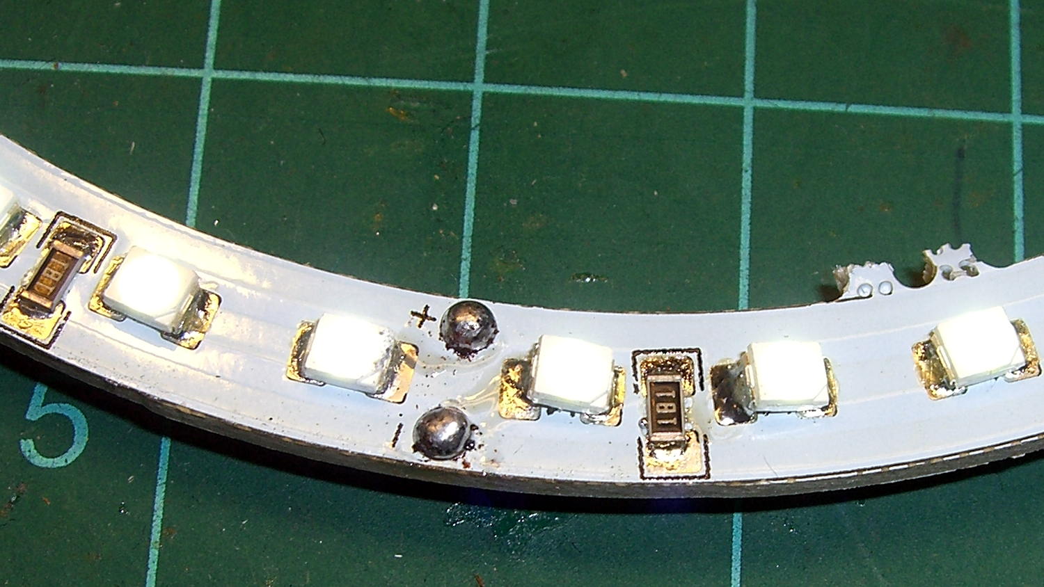
I picked up a pair of 125 mm OD white LED rings for the hand magnifier project from the usual eBay source, which arrived with the expected level of build quality:
LED Ring – SMD soldering
But, hey, all the LEDs lit up more-or-less uniformly.
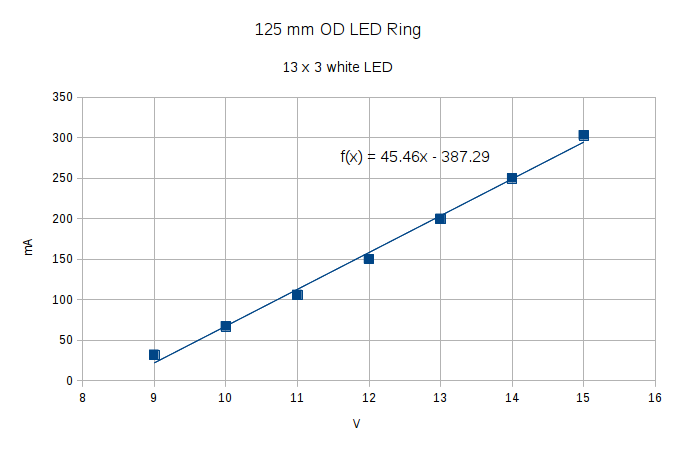
With 20 mA in each of 13 parallel strings of 3 white LEDs, the ring should draw 260 mA. It’s nominally a 12 V device sorta-kinda intended for automotive “angel eye” use, where the actual battery charging voltage runs around 14 V. The 180 Ω ballast resistors seem to be sized with that in mind:
LED Ring – SMD soldering
The reciprocal of that 45.5 mA/V slope is 220 V/mA = 220 Ω, which is close enough to the actual (we presume from their marking) 180 Ω resistors for comfort.
Driving it at 14 V to get 250 mA dissipates 3.5 W and makes it pleasantly warm.
For use with a magnifying lens, I think it deserves a brightness control. Perhaps hacking a bigger trimpot with a knob onto a cheap & tiny boost converter will suffice.
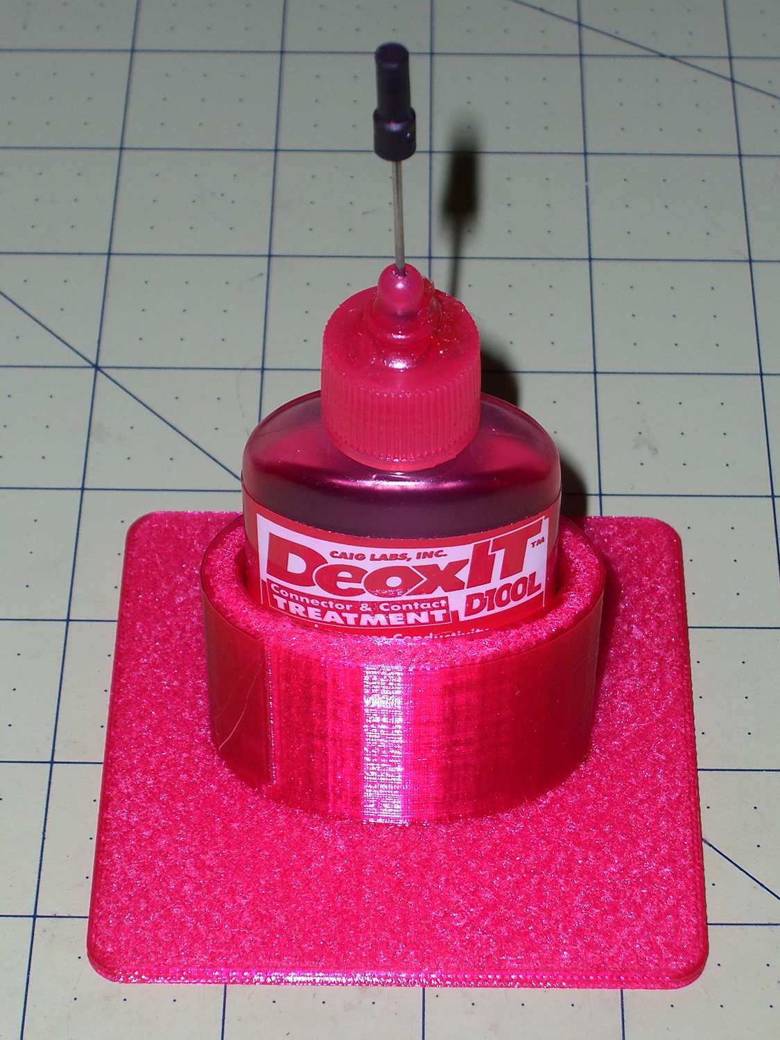
Having found my lifetime supply of DeoxIT slouched against something that didn’t appreciate a thin coating of red oil:
Caig DeoxIT bottle holder
The solid model consists of two squashed cylinders atop a slab:
DeoxIT Bottle Holder
Applying the resize() operator to both cylinders separately, before the difference() operation, maintains a uniform (and grossly overqualified) 5 mm wall thickness, which you wouldn’t get by squashing them after the difference().
The 2.5 mm slab gets nice, rounded corners from a hull() shrinkwrapping a quartet of squat cylinders; Slic3r applies Hilbert Curve infill to the top & bottom surfaces to produce a nice pattern. I admit to being easily pleased.
The OpenSCAD source code took about ten minutes to write and two hours to print:
I should mention the lamp test in case it comes in useful later on…
	digitalWrite(PIN_HEARTBEAT,LOW);	// turn off while panel blinks

	analogWrite(PIN_DIMMING,LEDS_ON);	// enable LED array

	for (byte i=0; i<NUMROWS; i++) {
		for (byte j=0; j<NUMCOLS; j++) {
			LEDs[i].ColR = LEDs[i].ColG = LEDs[i].ColB = 0x80 >> j;
			for (byte k=0; k<NUMROWS; k++) {
				UpdateLEDs(k);
				delay(25);
				if (GeigerTicked) {
					GeigerTicked = false;
					TogglePin(PIN_HEARTBEAT);
				}
			}
		LEDs[i].ColR = LEDs[i].ColG = LEDs[i].ColB = 0;
		}
	}
	UpdateLEDs(NUMROWS-1);			// clear the last LED
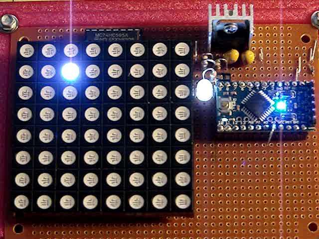
Updating / multiplexing all the rows inside the inner loop with a 25 ms pause produces distinct flashes and demonstrates that each LED operates separately from all the others:
Lamp Test
The lamp test ends with all the LEDs turned off, but having the array gradually fill with light looked odd.
After some tinkering, I added the GeigerTicked conditional to handshake with the Geiger pulse interrupt handler, thus producing a nice random time at the end of the loop. Feed that mostly random time into the hash function, use the hash as the random number seed, then set all the LEDs using random(2) function calls:
	randomSeed(jenkins_one_at_a_time_hash((char *)GeigerTime,4));

	for (byte Row=0; Row<NUMROWS; Row++) {
		for (byte Col=0; Col<NUMCOLS; Col++) {		// Col runs backwards, but we don't care
			LEDs[Row].ColR |= random(2) << Col;
			LEDs[Row].ColG |= random(2) << Col;
			LEDs[Row].ColB |= random(2) << Col;
		}
		UpdateLEDs(Row);
	}

	GeigerTicks = 0;				// reset counter
	GeigerTicked = false;			// resume capture
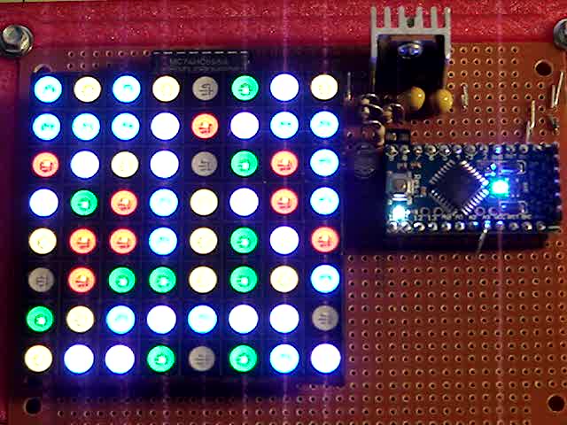
Which produced a more-or-less random fill that looked better:
Random Preload – bright
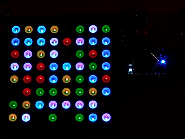
Underexposed to reduce the burnout (after a few Geiger events):
Random Preload – dim
There should be about eight of each color and, hey, it’s close enough.
In need of a quick-and-easy way to generate interesting data that would make an LED array do something and, what with radioactivity being the canonical source for random numbers, an ancient Aware Electronics RM-60 (*) emerged from the heap. The manual will get you up to speed on radiation detection, if you can read past the DOS-era program description.
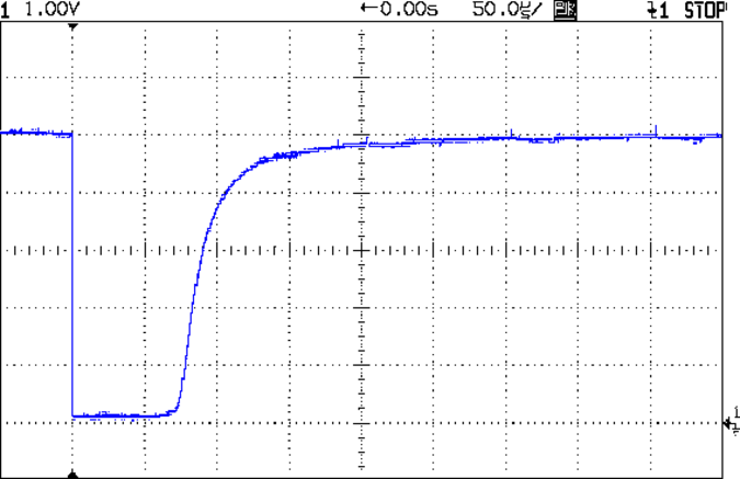
It produces a 100 µs (-ish) pulse for each detection:
Aware RM-60 Geiger Pulse
The minimum period seems to be around 500 µs, but I lack a sufficiently fierce radioactive source to verify that in any finite amount of time.
Seeing as how all we need is a little randomness, measuring the time when a pulse occurs will suffice; we’re not talking hardcore crypto.
With the pulse arriving on the Arduino D2 input, define an interrupt handler that sets a flag, bumps a counter, and records the current time in microseconds:
void GeigerHandler(void) {
	if (!GeigerTicked) {				// stop recording until loop() extracts the data
		GeigerTicked = true;
		GeigerTicks++;
		GeigerTime = micros();
	}
}
Define D2 as an input, turn on the pullup, and trigger that handler on the falling edge of the pulse:
pinMode(PIN_GEIGER,INPUT_PULLUP);	// RM-60 has its own pullup, but add this one, too

attachInterrupt((PIN_GEIGER - 2),GeigerHandler,FALLING);
Because an absolute timestamp of each event will produce an obviously non-random sequence of monotonically increasing numbers, I ran each four byte timestamp through a simple hash function to whiten the noise:
Then the only thing left to do is spin around the loop() while waiting for a particle to arrive:
	if (GeigerTicked) {
		digitalWrite(PIN_HEARTBEAT,HIGH);				// show a blip
		analogWrite(PIN_DIMMING,LEDS_OFF);				// turn off LED array to prevent bright glitch

		Hash = jenkins_one_at_a_time_hash((char *)&GeigerTime,4);	// whiten the noise

		GeigerTicked = false;							// flag interrupt handler to resume recording
//			printf("%9ld %08lx %08lx ",GeigerTicks,GeigerTime,Hash);
		SetLED(Hash);
	}
(*) Circuit Cellar readers of long memory will recognize the RM-60 as the McGuffin for the Radioactive Randoms column in 1990 that explained features of interrupt-driven code in a Micromint BASIC-52 board. Decades later, the hardware & software served as Prior Art in a patent suit that forced me to write some Rules of Engagement. Selah.