[Update: Wecome Hackaday! You may want to look at:
- Sakura drawing pen adapters
- Chiplotle driver modifications
- Supershape formula parameters
- Supershape demo
- The Python / Chiplotle code as a GitHub gist
Searching for 7475a will bring up many, many other posts]
After mentioning that I wished I still had my HP 7475A plotter, Dithermaster sent me one from his heap. As he explained, a mouse family had used it as a combination hotel-granary-latrine:
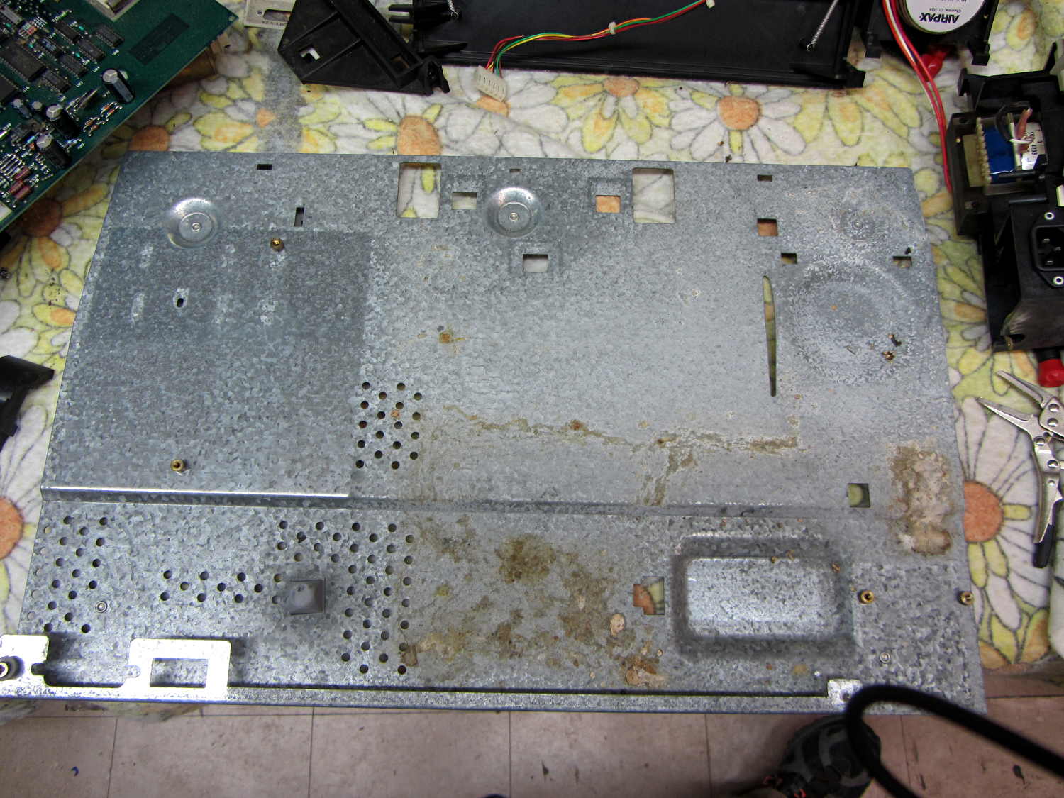
For whatever it’s worth, if you must get a bazillion seeds out of a plotter, ship it halfway across the continent: UPS performs a lengthy three-axis vibration test that shakes all the loose bits through the vents.
You’ll probably want the original HP 7475A documentation from the (unofficial) HP Computer Museum before digging in. Not mentioned anywhere: the two washers at the rear edge of the case are not identical. The one holding the power supply in place is slightly longer than the one at the serial connector. Mine are now color-coded to their locations.
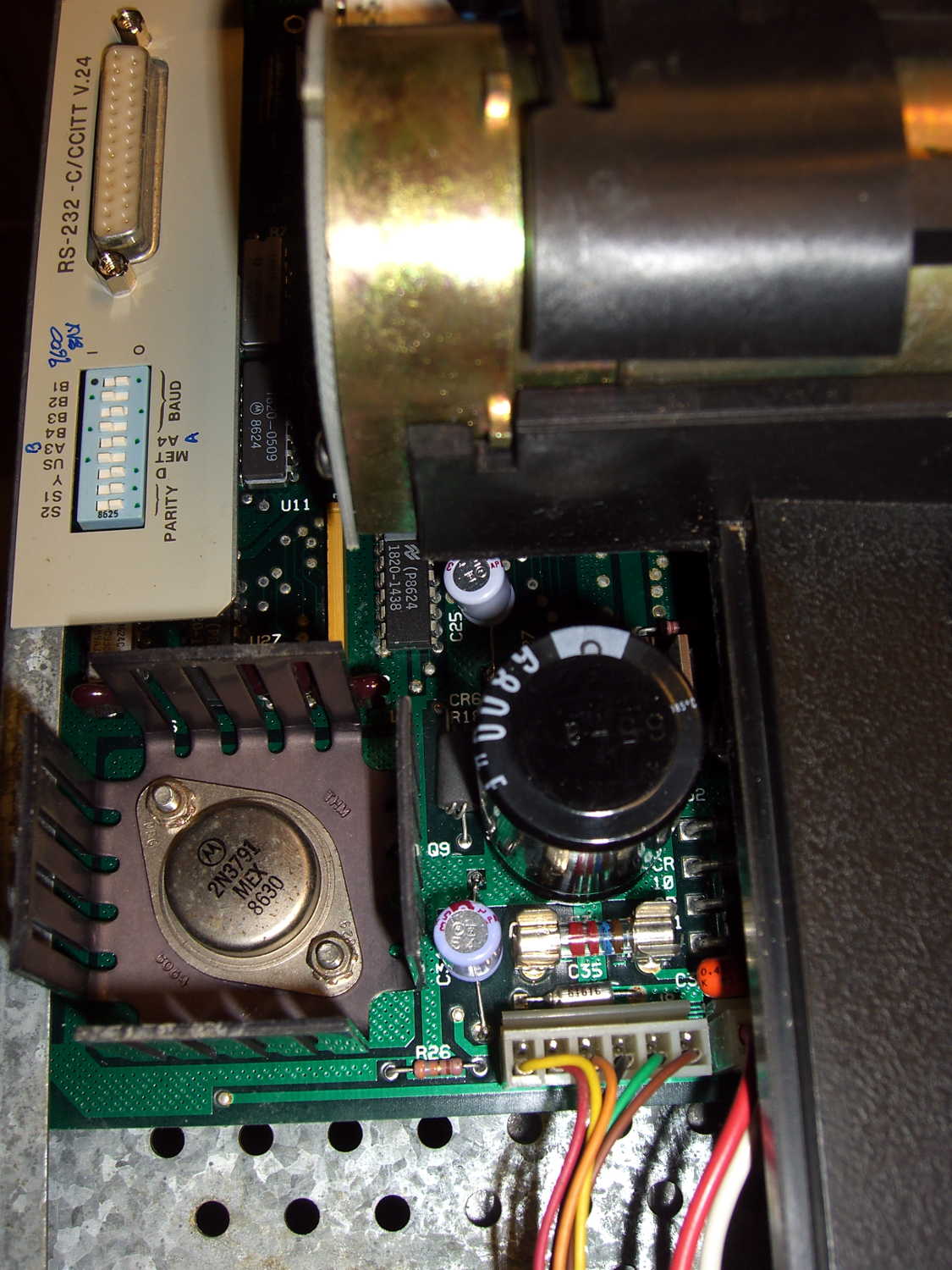
A critter whizzed on U13, the serial adapter chip, just beyond the big black filter capacitor:
I rinsed everything (except, no fool I, the membrane keypad at the front of the PCB) with warm water, flushed the latrine areas with dilute baking soda (alkaline, to neutralize the urea), rinsed with hot water, blew-dry with compressed air, then let the pieces sit for a few days.
After reassembly, the plotter didn’t start up. It’s a third of a century old, what did you expect?
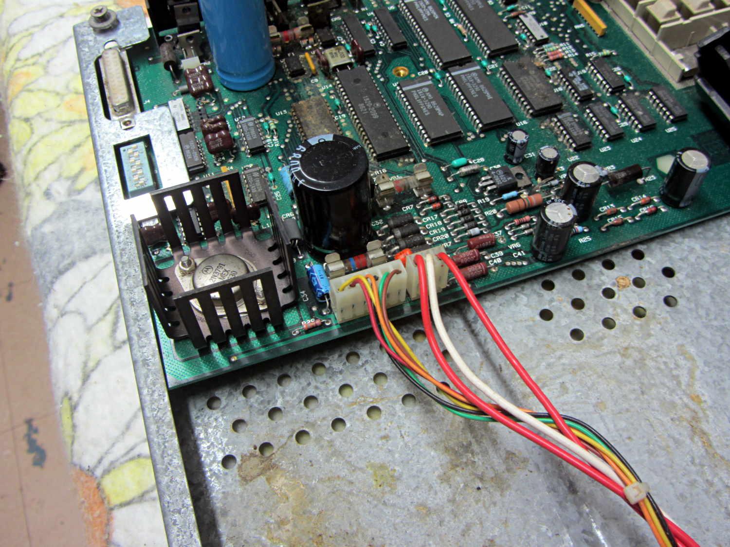
Measuring the electrolytic capacitors showed they were all in surprisingly good condition, with only C27 and C34 (on this Option 001 = RS-232 board) having moderately high ESR. They’re the pale blue axial caps just right of the heatsink, both 22 μF 25 V:
- C27: Processor Reset timing (U14 – p. 6-27/6-28)
- C34: +5 V filter cap (U21 – power supply p. 6-31)
The corresponding caps on the Option 002 = HP-IB board are C20 and C25. FWIW, if you have an HP-IB plotter, you should probably just hack an Arduino into the motor control connections and run it with Grbl; you’d get a bare-bones plotter eating G-Code, not HP-GL, but that’s not entirely a Bad Thing. Adapting the tool change code to handle the pen carousel is left as an exercise for the desperate.
I replaced the offending caps with 33 μF 50 V radial caps from the heap:
And then it performed its Demonstration Plot (load paper, hold down P1 + P2 buttons, turn on power) perfectly. The fossilized pens left no trace behind; we all expected that.
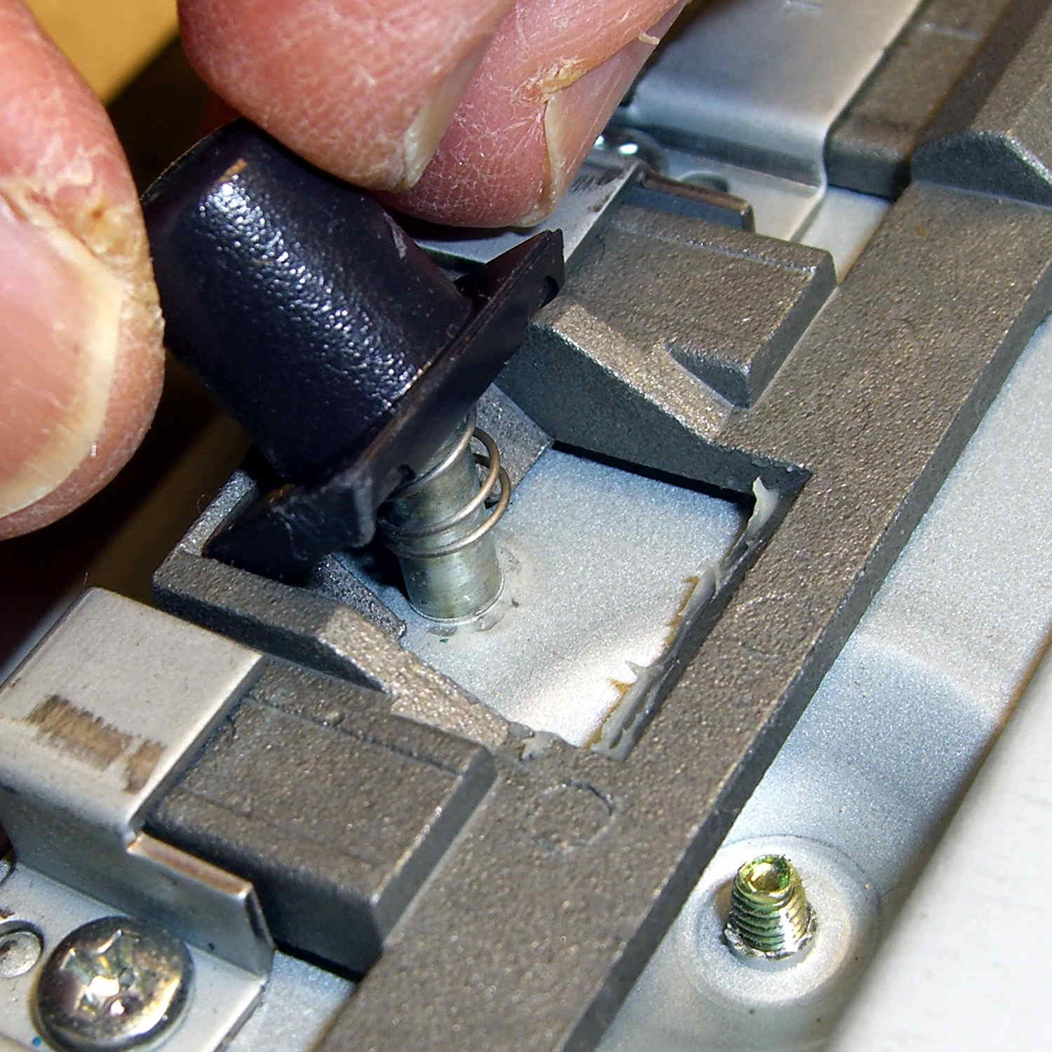
The serial port connection on the back required, from bottom to top:
- A null modem adapter
- A gender bender
- A 25-to-9 pin adapter
- Another gender bender
- A USB-serial adapter
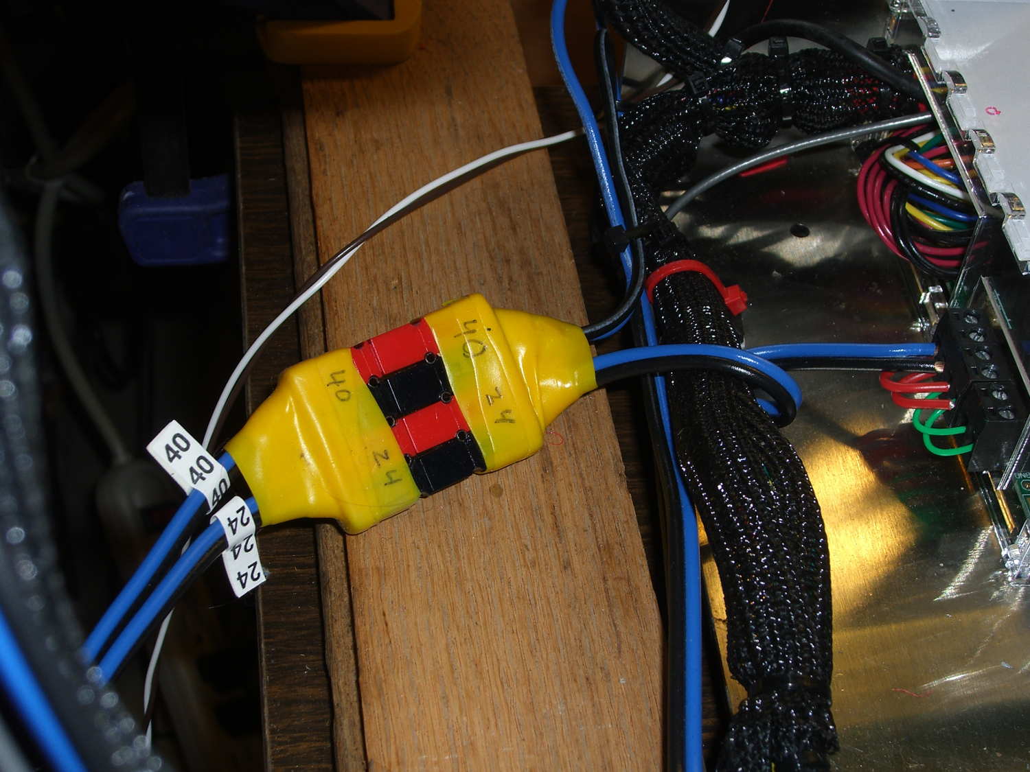
All of which came from the Big Box o’ Serial Adapters and produced this rather unsteady ziggurat:
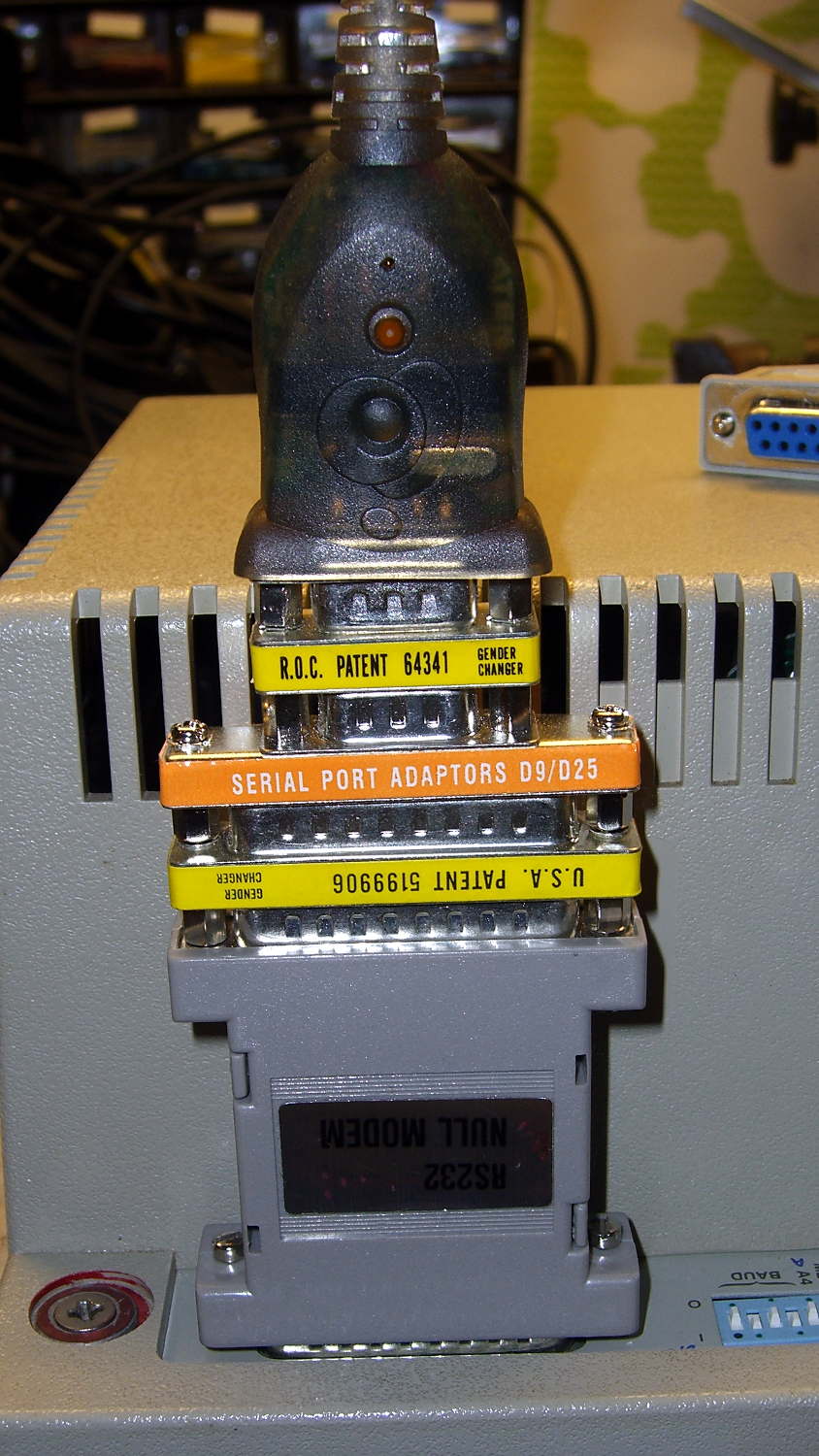
Seeing as how I’ve been adapting serial connections since before the HP 74754A was a thing, the Adapter Box has All! The! Adapter! Genders! plus Der Blinkenlights! They don’t come in nearly as handy nowadays, though, which is a Good Thing.
Some optimization pared down the ziggurat and added a short extension cable:
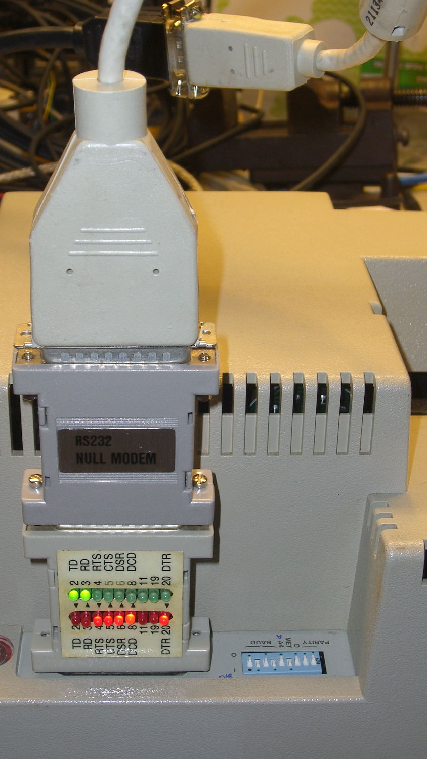
Eventually, I’ll build a custom cable, but it’s good enough for now.
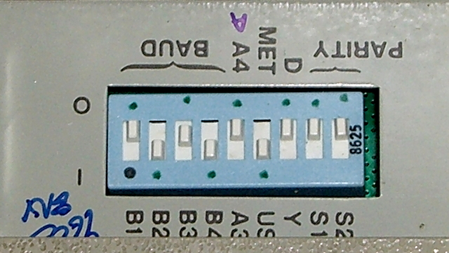
The switches select 9600 b/s serial data in 8N1 format. Yes, the plotter tops out at 9600 b/s, but remember we’re dealing with a pen plotter that executes terse ASCII commands. It offers both XON/XOFF and DTR/DSR hardware handshaking to prevent overruning the internal 1 kB buffer, plus a myriad other software-selectable options relevant to long-forgotten datacomm systems.
Lest I forget, dots now mark the switch settings for 9600 8N1, A (letter) paper, US (inch) units, direct serial connection:
And then it Just Worked: type IN;SP1; into minicom and the plotter grabs Pen 1. The rest is a simple matter of software.
Now, to deal with the pen situation…