Ed Nisley's Blog: Shop notes, electronics, firmware, machinery, 3D printing, laser cuttery, and curiosities. Contents: 100% human thinking, 0% AI slop.
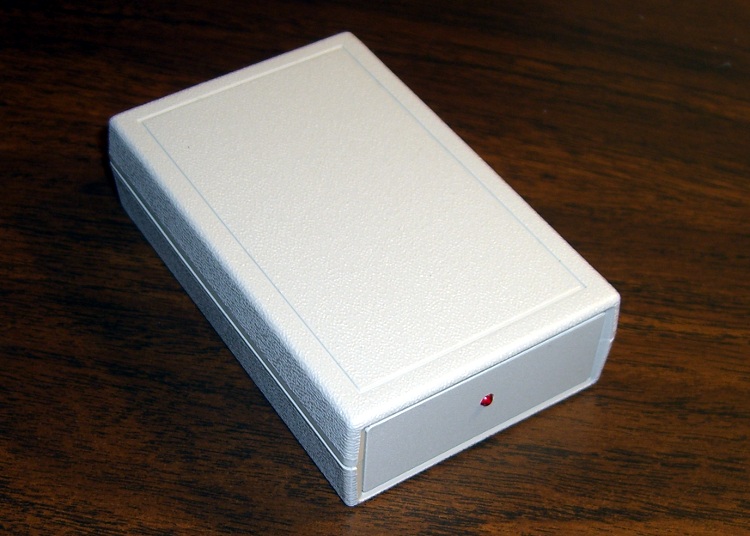
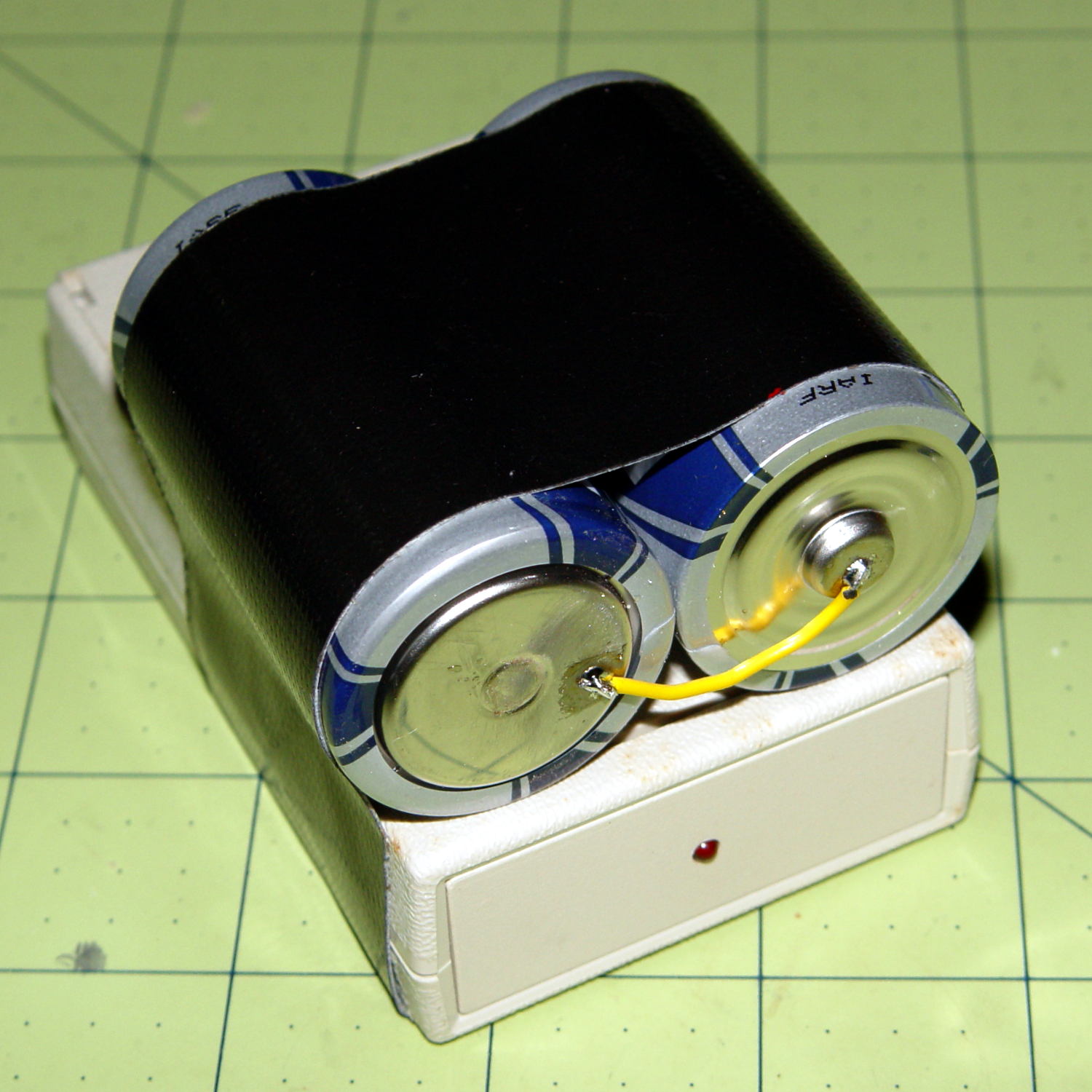
I duct-taped a pair of D cells onto the case and returned it to the bedroom shelf. According to the date scrawled on the tape, that was five years ago: 26 November 2010.
Over the last few months, the LED gradually faded from a blink to a steady glow as the battery voltage dropped below 2 V and the WWVB receiver output no longer reached the MOSFET’s threshold.
We’ll see how long these last:
Alpha Geek Clock – new batteries
Yeah, I should probably do something involving 3D printing…
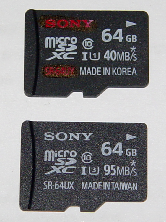
A little over a year ago, I bought two Sony 64 GB MicroSDXC cards (let’s call them A and B). Both cards failed after less than six months in service and were replaced under warranty with Cards C and D:
Sony 64 GB MicroSDXC cards – front
The top card (C) is the most recent failure, the bottom (D) is the as-yet-unused replacement for Card D. Note that the difference: SR-64UY vs. SR-64UX, the latter sporting a U3 speed rating.
Note that the failure involves the card’s recording speed, not its read-write ability or overall capacity. Card C still has its nominal 64 GB capacity and will store-and-replay data just fine, but it can’t write data at the 25 Mb/s rate required by the camera… which is barely a third of the card’s speed rating. Also note that the writing speed is always a minute fraction of the reading speed that you see on the card.
I use these in a Sony HDR-AS30V action camera on my bike, so it’s pure Sony all the way. Although I don’t keep track of every trip, I do have a pretty good idea of what happened…
In service: about 2015-07-10
Failed to record 1920×1080 @ 60 f/s video: 2015-09-22
In round numbers, that’s 70 days of regular use.
My NAS drive has room for about a month of video, depriving me of a complete record of how much data it absorbed, but from 2015-08-21 through 2015-09-22 there’s 425 GB from 25 trips in 30 days. Figuring the same intensity during the complete 70 days, it’s recorded 800 to 900 GB of data (including my verification test). With 60 GB available after formatting, that amounts to filling the card 14 times.
That’s reasonably close to the 1 TB of data I’d been estimating for the failures of Cards A and B, so these Sony cards reliably fail their speed rating after recording 750 GB, more or less, of data.
The simplest possible electrometer amplifier that might work:
Electrometer amp – LMC6081 schematic
The general idea is that the op amp will drive the (essentially) open-circuited inverting input to match the 2 V offset at the noninverting terminal, so that the output will stabilize above the LMC6081’s minimum useful output voltage (of about 1 V) and the gamma-ray pulses will go downward from there (it’s an inverting amp). The rebiasing network downstream from the output cap doesn’t appear in the hardware.
The small cap across the feedback resistor that would compensate / roll off the high-frequency response isn’t possible, unless you have a stockpile of teeny glass vacuum capacitors: the leakage resistance must be far more than 100 GΩ and my collection lacks anything like that. A Teflon-insulated gimmick capacitor wouldn’t be stable enough and would probably still leak crazy current.
Normal electrometer amps operate at essentially DC and amplify an actual current from the ionization chamber. In this case, the radiation level is zero, there’s no chamber current, I’m looking for small pulses generated by gamma ray events, and the amplifier must have reasonable AC response. It’s not clear that circuit can work, but it’s a starting point.
It turned into a hairball:
Electrometer Amp – 10 Gohm Rf
The LMC6081IN is socketed, with the inverting input pin bent outward and soldered to the flying junction of the 100 kΩ input / OMG resistor (which prevents inadvertent shorts from the 24 V chamber bias) and the glass-body feedback resistor. The socket sits end-on in a puddle of epoxy, so I can swap op amps as needed.
The 100 GΩ feedback resistor didn’t work well at all:
LMC6081 100 G – out – noninv level – matched
The lower trace shows the 10.2 VDC offset at the noninverting input, which is what it took to drive the output from near 0 V to the 11.4 V in the upper trace, with no proportional change in between. I replaced the schematic’s 1 MΩ / 220 kΩ resistors with the 20 turn trimpot shown in the photo in order to find that bias condition. Obviously, the op amp acts as an open-loop comparator, not a linear amplifier, and no amount of waiting for it to stabilize would change that outcome.
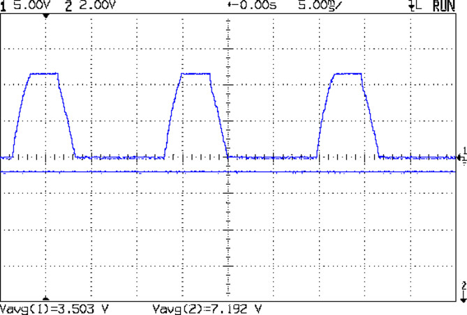
It’s possible the resistor has failed open, but, frankly, the difference between “100 GΩ” and “open circuit” probably doesn’t amount to much. Note, however, that there’s absolutely no 60 / 120 Hz interference or noise, which continues to surprise me; removing the shield cap and teasing the twiddlepot slams the output with a 60 Hz trapezoid:
LMC6081 100 G – out – noninv level
Swapping in a 10 GΩ resistor produced a smoothly changing output for biases between about 1 V and 8 V, so it’s behaving like an op amp should. Setting the non-inverting terminal to 8 V puts the output voltage at 6.3 V, which means the 10 GΩ resistor drops about 1.7 V to pull 170 pA from the inverting input (which is presumably at 8 V give-or-take a bit) and the chamber electrode. The LMC6081 spec says a maximum of 4 pA (for the I version, which is what I have), so:
My cleanliness isn’t up to par
The chamber delivers quite a bit more zero-radiation current than I expected
The op amp’s input got toasted despite my efforts toward a static-free installation
Hard to choose among those options, it is, indeed.
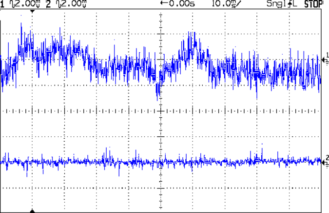
With the bias set to produce a 6 VDC output, the AC coupled signal doesn’t seem promising:
LMC6081 10 G Rf – out and Vplus in – AC 2 mV div
The lower trace is the bias voltage applied to the noninverting input, which looks reasonably clean. The sweep triggers from the power line; there’s still no 60 Hz interference.
All those flying components are, as you’d expect, microphonic beyond belief: jumping on the concrete basement floor produces a corresponding bounce in the trace that may be due to air currents or noise, for all I can tell. Even with the chamber sitting on a loose cloth pad, tapping the workbench produces 10 s of slowly decaying oscillation, admittedly at a much lower frequency than the noise in that trace.
A single gamma ray event producing an unreasonably high 10 fA chamber current will cause a downward (it’s an inverting amplifier) pulse that amounts to a mere 100 µV, a pulse that obviously isn’t visible against all that racket. You might convince yourself that the event at the center of the top trace comes from a gamma ray, but you’d probably be wrong.
In a normal electrometer amp, a stiff low-pass filter discards all the noise and isolates the DC signal corresponding to the steady-state chamber current from the ionizing radiation. Given that the pulses are on the order of 5 ms wide, there’s no obvious way to discard most of the noise without also tossing the signal.
Pending more thought, I’d say this was definitely fun while it lasted…
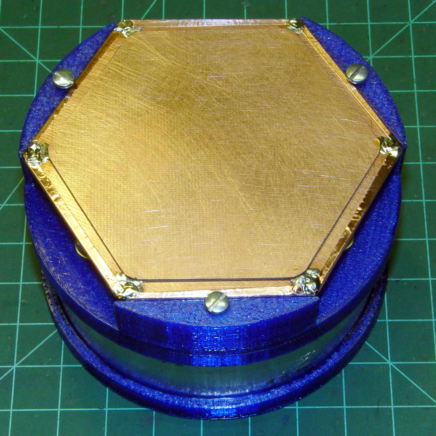
An undrilled double-sided circuit board with the edges bonded together doesn’t look like much:
Electrometer amp – undrilled shield planes
Soldering a smaller hex to the center of the bonded plate produces an isolated plane:
Electrometer amp – finished shield planes
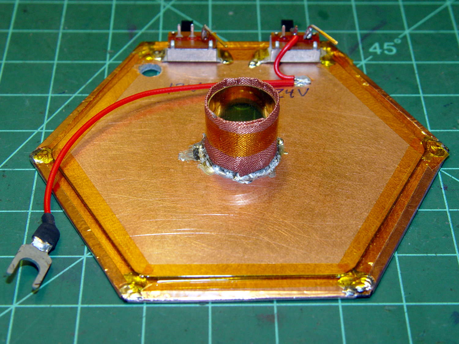
The copper fabric tape wrapped around a brass tube soldered to the isolated plane contacts the ionization chamber shell around the central contact and (should) provide complete shielding. Kapton tape around the edges reduces the likelihood of inadvertent shorts.
Working with a shield at +24 V gave me the shakes, so this one confines the chamber bias to the isolated hex and shell, with the larger hex at circuit common (a.k.a. ground). The isolated plane has about 275 pF to the ground plane, which isn’t a Bad Thing at all. In principle, the chamber bias doesn’t need a switch, because there’s no current drain, but I vastly prefer having cold circuitry before popping the lid.
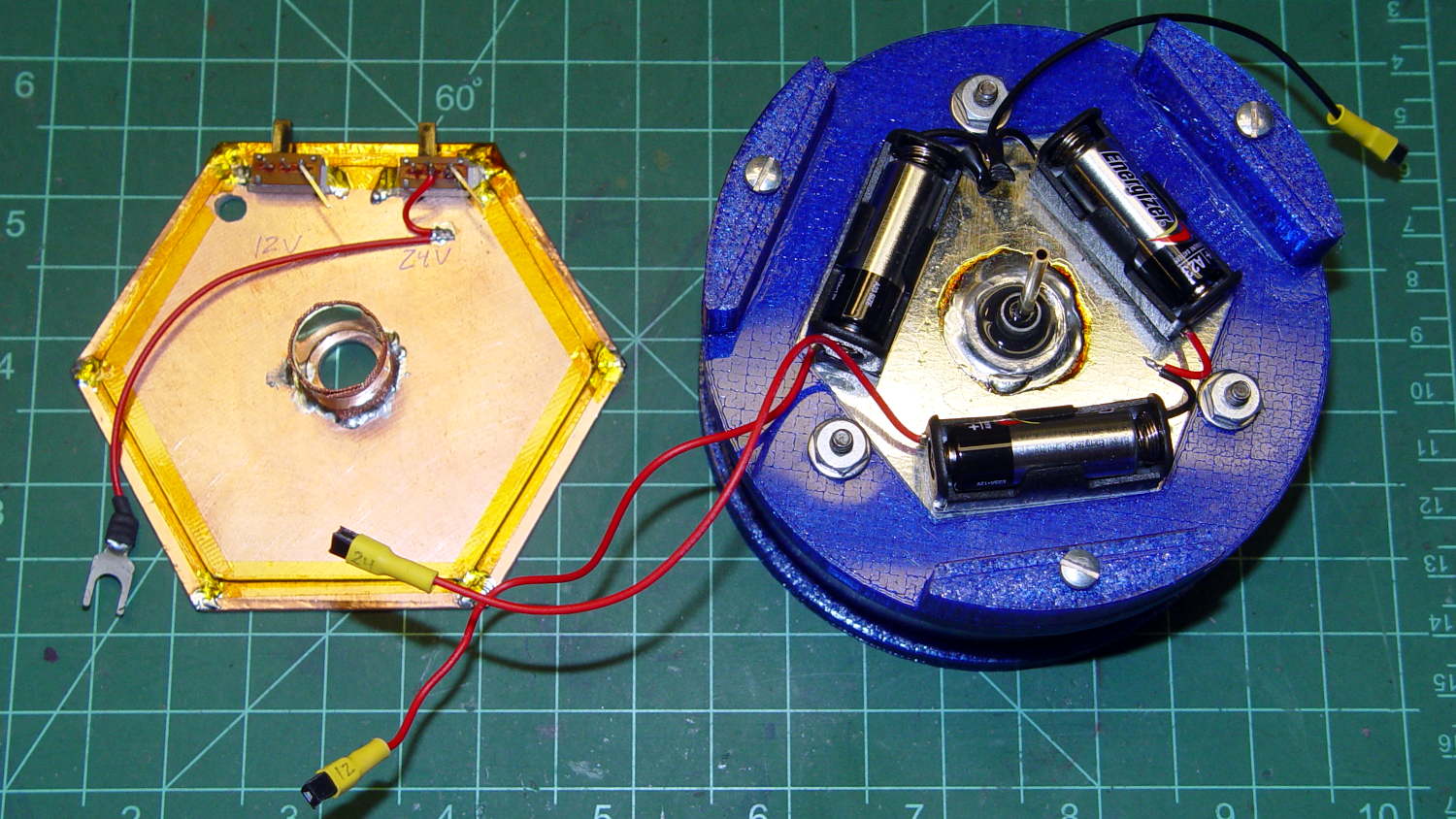
If I had a small DPST switch, I’d use it:
Electrometer amp – chamber – shield planes
As it stands, one switch controls the +24 V chamber bias and the other switches +12 V power to the electrometer amp front end, with simpleminded connectors so I can separate the pieces.
We’ll see how well all that works in practice.
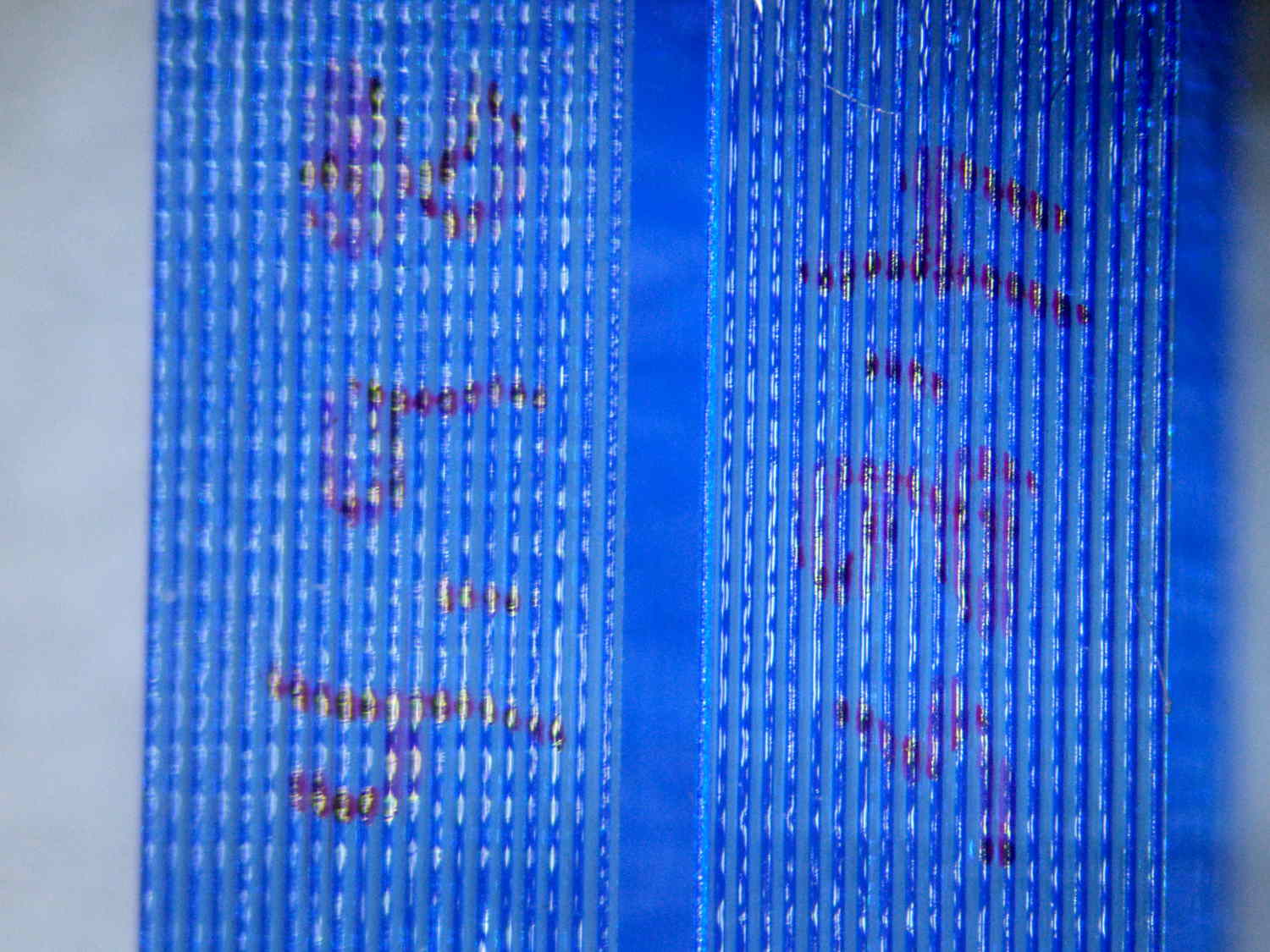
An alert reader will notice the tiny difference between the blue PETG shapes in the two pictures. The bottom one comes from the revised code, of course.
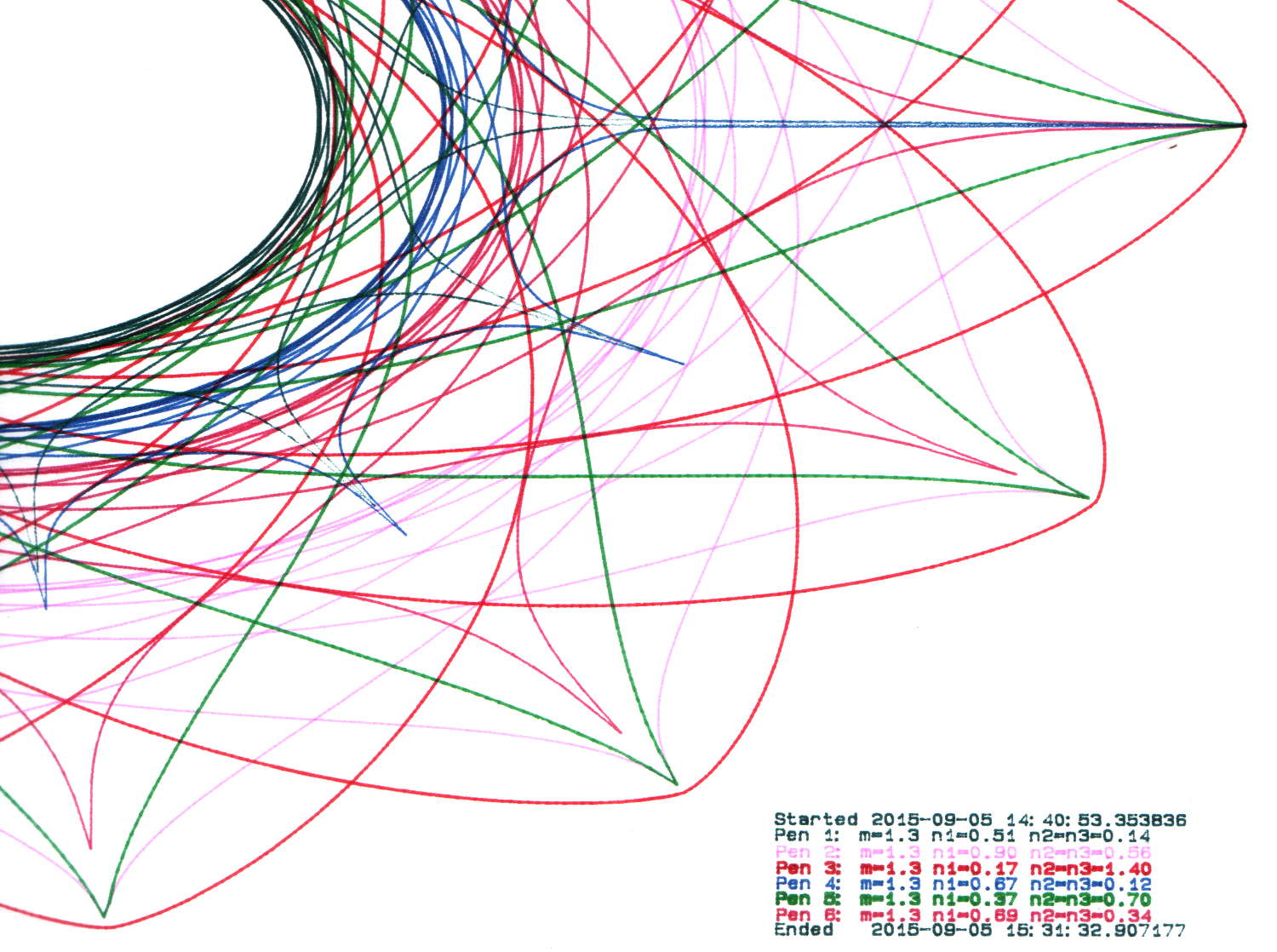
By now, I have half a dozen baggies each containing half a dozen plotter pens, plus a demo program that can produce good-looking Superformula plots, so I can do this without any hassle:
HP 7475A 2541A 68465 – Random pens
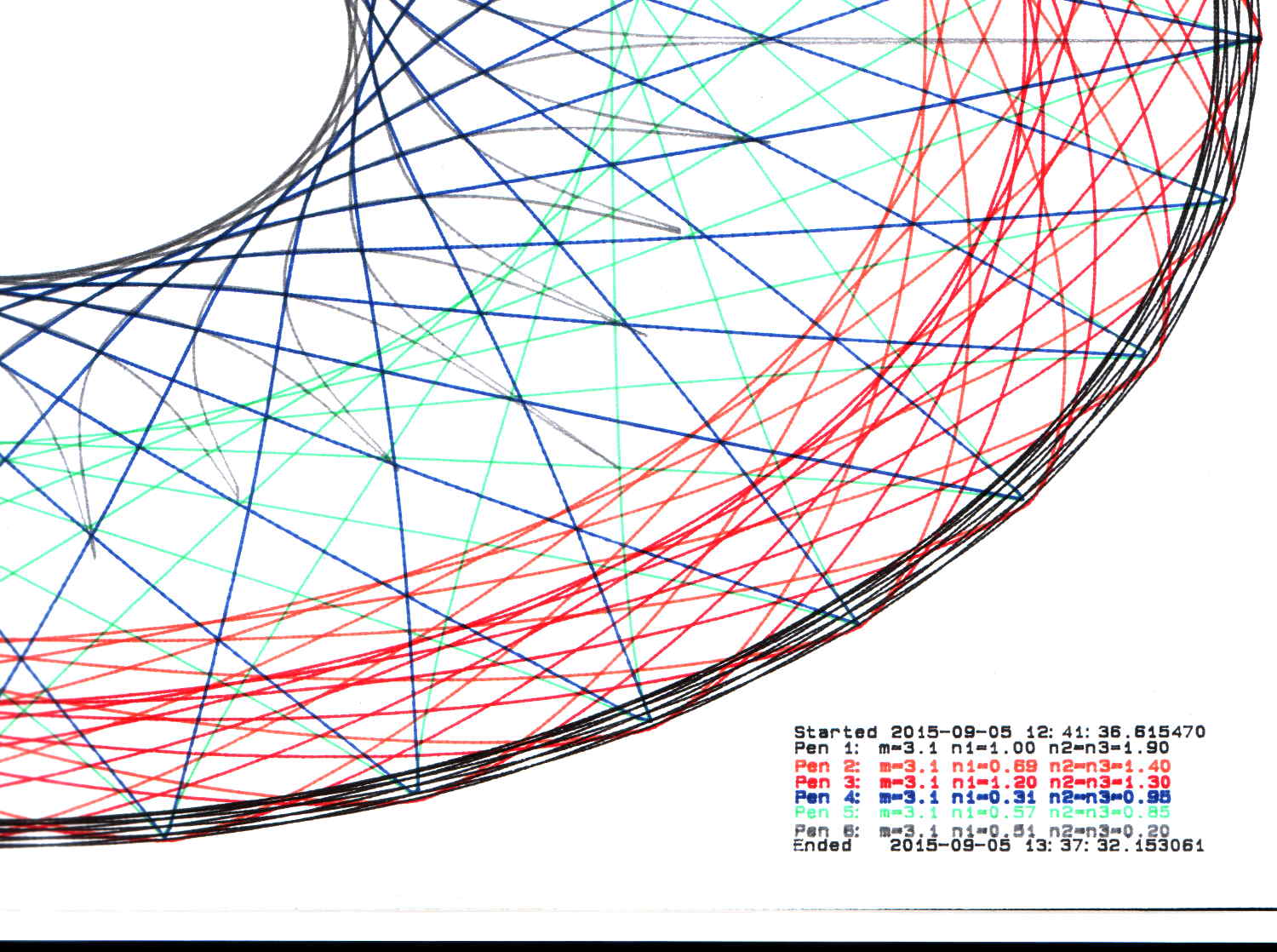
And this:
HP 7475A 2641V 26599 – Random pens
I must confess to not being good at withstanding temptation; the second plot comes from another HP 7475A plotter that I won on eBay:
Stacked HP 7475A Plotters
Apparently, nobody else wanted a plotter advertised as “non-working”, leaving me as the sole bidder. The photos showed that it powered up properly, sported a serial (not HPIB) interface, had an (empty) carousel with rubber pen boots (that were, oddly enough, not fossilized), and came with a complete set of manuals. Turns out any one of those items sells for more than the entire package, so I can part it out, flip the pieces, and Profit! if I were so inclined.
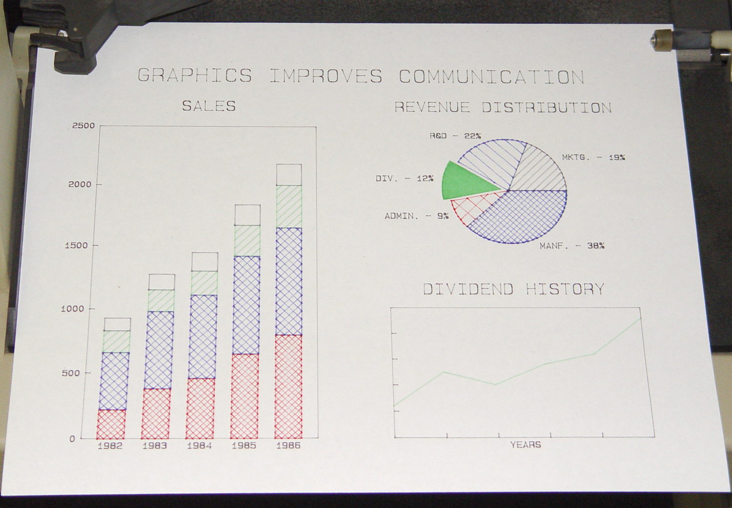
Load the carousel with a handful of restored pens, insert a sheet of paper, hold down the P1 + P2 buttons, flip the power switch, and out comes a perfectly drawn demo plot:
Victoreen 710-104 Ionization Chamber Fittings – Show V2
There’s not much difference from the first iteration, apart from a few code cleanups. The engraved text is kinda-sorta gratuitous, but I figured having the circuit board dimensions on all the key parts would avoid heartache & confusion; the code now autosizes the board to the holder OD. Skeletonizing the board template didn’t save nearly as much printing time as I expected, though.
Now I can build a second electrometer amp without dismantling the two-transistor version.
The OpenSCAD source code:
// Victoreen 710-104 Ionization Chamber Fittings
// Ed Nisley KE4ZNU August 2015

Layout = "Show";
					// Show - assembled parts
					// Build - print can parts + shield
					// BuildShield - print just the shield
					// BuildHolder - print just the can cap & PCB base
					// CanCap - PCB insulator for 6-32 mounting studs
					// CanBase - surrounding foot for ionization chamber
					// CanRim - generic surround for either end of chamber
					// PCB - template for cutting PCB sheet
					// PCBBase - holder for PCB atop CanCap
					// Shield - electrostatic shield shell

//- Extrusion parameters must match reality!
//  Print with 2 shells and 3 solid layers

ThreadThick = 0.25;
ThreadWidth = 0.40;

HoleWindage = 0.2;

Protrusion = 0.1;			// make holes end cleanly

AlignPinOD = 1.75;			// assembly alignment pins = filament dia

inch = 25.4;

function IntegerMultiple(Size,Unit) = Unit * ceil(Size / Unit);

//- Screw sizes

Tap4_40 = 0.089 * inch;
Clear4_40 = 0.110 * inch;
Head4_40 = 0.211 * inch;
Head4_40Thick = 0.065 * inch;
Nut4_40Dia = 0.228 * inch;
Nut4_40Thick = 0.086 * inch;
Washer4_40OD = 0.270 * inch;
Washer4_40ID = 0.123 * inch;


//----------------------
// Dimensions

OD = 0;											// name the subscripts
LENGTH = 1;

Chamber = [91.0,38];							// Victoreen ionization chamber dimensions

Stud = [										// stud welded to ionization chamber lid
	[6.5,IntegerMultiple(0.8,ThreadThick)],		// flat head -- generous clearance
	[4.0,9.5],									// 6-32 screw -- ditto
];
NumStuds = 3;									// this really isn't much of a variable...
StudAngle = 360/NumStuds;
StudSides = 6;									// for hole around stud

BCD = 2.75 * inch;								// mounting stud bolt circle diameter

PlateThick = 2.0;								// minimum layer atop and below chamber ends
RimHeight = 4.0;								// extending along chamber perimeter
WallHeight = RimHeight + PlateThick;
WallThick = 3.0;								// thick enough to be sturdy & printable
CapSides = 8*6;									// must be multiple of 4 & 3 to make symmetries work out right

RimOD = Chamber[OD] + 2*WallThick;

echo(str("Rim OD: ",RimOD));

//PCBFlatsOD = 82.0;							// desired hex dia flat-to-flat
PCBFlatsOD = floor(RimOD*cos(30)) - 2.0;		//  .. maximum possible
//PCBFlatsOD = floor(Chamber[OD]*cos(30)) - 2.0;	//  .. chamber fitting
PCBClearance = ThreadWidth;						// clearance beyond each flat for mounting

PCBThick = 1.1;
PCBActual = [PCBFlatsOD/cos(30),PCBThick];		// OD = tip-to-tip
PCBCutter = [(PCBFlatsOD + 2*PCBClearance)/cos(30),PCBThick - ThreadThick];		// OD = tip-to-tip dia + clearance

PCBSize = str(PCBFlatsOD, " mm");
echo(str("Actual PCB across flats: ",PCBFlatsOD));
echo(str(" ... tip-to-tip dia: ",PCBActual[OD]));
echo(str(" ... thickness: ",PCBActual[LENGTH]));

HolderHeight = 13.0 + PCBCutter[LENGTH];		// thick enough for PCB to clear studs + batteries
HolderShelf = 2.0;								// shelf under PCB edge
HolderTrim = 5.0;								// remove end of holder to clear PCB edge solder blobs
echo(str("Holder trim distance: ",HolderTrim));
HolderTrimAngle = StudAngle/2 - 2*atan(HolderTrim*cos(StudAngle/2)/(PCBActual[OD]/2));	// atan is close for small angles
echo(str(" ... angle: ",HolderTrimAngle));

PinAngle = 15;									// alignment pin angle on either side of holder screw

echo(str("PCB holder across flats: ",PCBCutter[OD]*cos(30)));
echo(str(" ... height: ",HolderHeight));

ShieldInset = 0.5;								// shield inset from actual PCB flat
ShieldWall = 2.0;								// wall thickness
ShieldLid = 6*ThreadThick;						// top thickness (avoid one infill layer)
Shield = [(PCBFlatsOD - 2*ShieldInset)/ cos(30),40.0];		// electrostatic shield shell dimensions

TextSize = 4;
TextCharSpace = 1.05;
TextLineSpace = TextSize + 2;
TextDepth = 1*ThreadThick;

//----------------------
// Useful routines

module PolyCyl(Dia,Height,ForceSides=0) {			// based on nophead's polyholes

  Sides = (ForceSides != 0) ? ForceSides : (ceil(Dia) + 2);

  FixDia = Dia / cos(180/Sides);

  cylinder(r=(FixDia + HoleWindage)/2,
			h=Height,
		$fn=Sides);
}

//- Locating pin hole with glue recess
//  Default length is two pin diameters on each side of the split

module LocatingPin(Dia=AlignPinOD,Len=0.0) {

	PinLen = (Len != 0.0) ? Len : (4*Dia);

	translate([0,0,-ThreadThick])
		PolyCyl((Dia + 2*ThreadWidth),2*ThreadThick,4);

	translate([0,0,-2*ThreadThick])
		PolyCyl((Dia + 1*ThreadWidth),4*ThreadThick,4);

	translate([0,0,-Len/2])
		PolyCyl(Dia,Len,4);

}

module ShowPegGrid(Space = 10.0,Size = 1.0) {

  RangeX = floor(100 / Space);
  RangeY = floor(125 / Space);

	for (x=[-RangeX:RangeX])
		for (y=[-RangeY:RangeY])
		translate([x*Space,y*Space,Size/2])
			%cube(Size,center=true);
}

//-----

module CanRim(BaseThick) {

	difference() {
		cylinder(d=Chamber[OD] + 2*WallThick,h=(WallHeight + BaseThick),$fn=CapSides);
		translate([0,0,BaseThick])
			PolyCyl(Chamber[OD],Chamber[LENGTH],CapSides);
	}

}

module CanCap() {

	difference() {
		CanRim(PlateThick + Stud[0][LENGTH]);

		translate([0,0,-Protrusion])											// central cutout
			rotate(180/6)
				cylinder(d=BCD,h=Chamber[LENGTH],$fn=6);						//  ... reasonable size

		for (i=[0:(NumStuds - 1)])												// stud clearance holes
			rotate(i*StudAngle)
				translate([BCD/2,0,0])
					rotate(180/StudSides) {
						translate([0,0,PlateThick])
							PolyCyl(Stud[0][OD],Chamber[LENGTH],StudSides);
						translate([0,0,-Protrusion])
							PolyCyl(Stud[1][OD],Chamber[LENGTH],StudSides);
					}

		for (i=[0:(NumStuds - 1)], j=[-1,1])									// PCB holder alignment pins
			rotate(i*StudAngle + j*PinAngle + 60)
				translate([Chamber[OD]/2,0,0])
					rotate(180/4 - j*PinAngle)
						LocatingPin(Len=2*(PlateThick + Stud[0][LENGTH]) - 4*ThreadThick);

		translate([-(BCD/2),0,-Protrusion])
			rotate(90) mirror()
				linear_extrude(height=(ThreadThick + Protrusion))
				text(PCBSize,size=6,font="Liberation Mono:style=bold",halign="center",valign="center");
	}

}

module CanBase() {

	difference() {
		CanRim(PlateThick);
		translate([0,0,-Protrusion])
			PolyCyl(Chamber[OD] - 2*RimHeight,Chamber[LENGTH],CapSides);
	}
}

module PCBTemplate() {

	CutLen = 10*PCBActual[LENGTH];

	difference() {
		cylinder(d=PCBActual[OD],h=PCBActual[LENGTH],$fn=6);		// actual PCB size
		translate([0,0,-Protrusion])
			cylinder(d=8,h=CutLen,$fn=12);
		if (true)
			for (i=[0:5])											// empirical cutouts
				rotate(i*60 + 30)
					translate([PCBFlatsOD/3,0,-Protrusion])
						rotate(60)
							cylinder(d=0.43*PCBActual[OD],h=CutLen,$fn=3);

		translate([PCBActual[OD]/4,0,(PCBActual[LENGTH] - ThreadThick)])
			linear_extrude(height=(ThreadThick + Protrusion),convexity=1)
			text(PCBSize,size=4,font="Liberation Mono:style=bold",halign="center",valign="center");

	}
}

module PCBBase() {

	intersection() {
		difference() {
			cylinder(d=Chamber[OD] + 2*WallThick,h=HolderHeight,$fn=CapSides);		// outer rim

			rotate(30) {
				translate([0,0,-Protrusion])										// central hex
					cylinder(d=(PCBActual[OD] - HolderShelf/cos(30) - HolderShelf/cos(30)),h=2*HolderHeight,$fn=6);

				translate([0,0,HolderHeight - PCBCutter[LENGTH]])					// hex PCB recess
					cylinder(d=PCBCutter[OD],h=HolderHeight,$fn=6);

				for (i=[0:NumStuds - 1])											// PCB retaining screws
					rotate(i*StudAngle + 180/(2*NumStuds))
						translate([(PCBCutter[OD]*cos(30)/2 + Clear4_40/2 + ThreadWidth),0,-Protrusion])
							rotate(180/6)
								PolyCyl(Tap4_40,2*HolderHeight,6);

				for (i=[0:(NumStuds - 1)], j=[-1,1])								// PCB holder alignment pins
					rotate(i*StudAngle + j*PinAngle + 180/(2*NumStuds))
						translate([Chamber[OD]/2,0,0])
							rotate(180/4 - j*PinAngle)
								LocatingPin(Len=2*(HolderHeight - 4*ThreadThick));
			}

			if (false)
			for (i=[0:NumStuds - 1])
				rotate(i*StudAngle - StudAngle/2)							// segment isolation - hex sides
					translate([0,0,-Protrusion]) {
						linear_extrude(height=2*HolderHeight)
							polygon([[0,0],[Chamber[OD],0],[Chamber[OD]*cos(180/NumStuds),Chamber[OD]*sin(180/NumStuds)]]);
					}

			translate([-(PCBFlatsOD/2 + PCBClearance - HolderShelf),0,HolderHeight/2])
				rotate([0,90,0]) rotate(90)
					linear_extrude(height=(ThreadWidth + Protrusion))
					text(PCBSize,size=6,font="Liberation Mono:style=bold",halign="center",valign="center");

		}

		for (i=[0:NumStuds - 1])
			rotate(i*StudAngle + StudAngle/2 - HolderTrimAngle/2)								// trim holder ends
				translate([0,0,-Protrusion]) {
					linear_extrude(height=2*HolderHeight)
						polygon([[0,0],[Chamber[OD],0],[Chamber[OD]*cos(HolderTrimAngle),Chamber[OD]*sin(HolderTrimAngle)]]);
				}

	}
}

//-- Electrostatic shield
//		the cutouts are completely ad-hoc

module ShieldShell() {

CutHeight = 7.0;

	difference() {
		cylinder(d=Shield[OD],h=Shield[LENGTH],$fn=6);							// exterior shape

		translate([0,0,-ShieldLid])												// interior
			cylinder(d=(Shield[OD] - 2*ShieldWall/cos(30)),h=Shield[LENGTH],$fn=6);

		translate([0,0,Shield[LENGTH] - TextDepth])
		rotate(180) {
			translate([0,0.3*Shield[OD] - 0*TextLineSpace,0])
				linear_extrude(height=(TextDepth + Protrusion))
					text("Gamma",size=TextSize,spacing=TextCharSpace,font="Liberation:style=bold",halign="center",valign="center");
			translate([0,0.3*Shield[OD] - 1*TextLineSpace,0])
				linear_extrude(height=(TextDepth + Protrusion))
					text("Ionization",size=TextSize,spacing=TextCharSpace,font="Liberation:style=bold",halign="center",valign="center");
			translate([0,0.3*Shield[OD] - 2*TextLineSpace,0])
				linear_extrude(height=(TextDepth + Protrusion))
					text("Amplifier",size=TextSize,spacing=TextCharSpace,font="Liberation:style=bold",halign="center",valign="center");
			translate([0,-0.3*Shield[OD] + 1*TextLineSpace,0])
				linear_extrude(height=(TextDepth + Protrusion))
					text("KE4ZNU",size=TextSize,spacing=TextCharSpace,font="Liberation:style=bold",halign="center",valign="center");
			translate([0,-0.3*Shield[OD] + 0*TextLineSpace,0])
				linear_extrude(height=(TextDepth + Protrusion))
					text("2015-08",size=TextSize,spacing=TextCharSpace,font="Liberation:style=bold",halign="center",valign="center");
		}

		translate([Shield[OD]/4 - 20/2,Shield[OD]/2,(CutHeight - Protrusion)/2])	// switch
			rotate(90)
				cube([Shield[OD],20,CutHeight + Protrusion],center=true);

		if (false)
		translate([-Shield[OD]/4 + 5/2,Shield[OD]/2,(CutHeight - Protrusion)/2])	// front
			rotate(90)
				cube([Shield[OD],5,CutHeight + Protrusion],center=true);

		translate([-Shield[OD]/2,0,(CutHeight - Protrusion)/2])						// right side
				cube([Shield[OD],7,CutHeight + Protrusion],center=true);

		translate([0,(Shield[OD]*cos(30)/2 - ThreadWidth),0.75*Shield[LENGTH]])
			rotate([90,0,180]) rotate(00)
				linear_extrude(height=(ThreadWidth + Protrusion))
				text(PCBSize,size=5,font="Liberation Mono:style=bold",halign="center",valign="center");
	}

}

//----------------------
// Build it

ShowPegGrid();

if (Layout == "CanRim") {
	CanRim();
}

if (Layout == "CanCap") {
	CanCap();
}

if (Layout == "CanBase") {
	CanBase();
}

if (Layout == "PCBBase") {
	PCBBase();
}

if (Layout == "PCB") {
	PCBTemplate();
}

if (Layout == "Shield") {
	ShieldShell();
}

if (Layout == "Show") {
	CanBase();
	color("Orange",0.5)
		translate([0,0,PlateThick + Protrusion])
			cylinder(d=Chamber[OD],h=Chamber[LENGTH],$fn=CapSides);
	translate([0,0,(2*PlateThick + Chamber[LENGTH] + 2*Protrusion)])
		rotate([180,0,0])
			CanCap();
	translate([0,0,(2*PlateThick + Chamber[LENGTH] + 5.0)])
		PCBBase();
	color("Green",0.5)
		translate([0,0,(2*PlateThick + Chamber[LENGTH] + 7.0 + HolderHeight)])
			rotate(30)
				PCBTemplate();
	translate([0,0,(2*PlateThick + Chamber[LENGTH] + 15.0 + HolderHeight)])
		rotate(-30)
			ShieldShell();}

if (Layout == "Build") {

	translate([-0.50*Chamber[OD],-0.60*Chamber[OD],0])
		CanCap();

	if (false)
		translate([0.55*Chamber[OD],-0.60*Chamber[OD],0])
			rotate(30)
				translate([0,0,Shield[LENGTH]])
					rotate([0,180,0])
						ShieldShell();
	if (true)
		translate([0.55*Chamber[OD],-0.60*Chamber[OD],0])
			rotate(30)
				PCBTemplate();

	if (true)
		translate([-0.25*Chamber[OD],0.60*Chamber[OD],0])
			CanBase();
		translate([0.25*Chamber[OD],0.60*Chamber[OD],0])
			PCBBase();
}

if (Layout == "BuildHolder") {
	translate([-0.25*Chamber[OD],0,0])
		CanCap();
	translate([0.25*Chamber[OD],0,0])
		PCBBase();
}

if (Layout == "BuildShield") {

	translate([0,0,Shield[LENGTH]])
		rotate([0,180,0])
				ShieldShell();


}
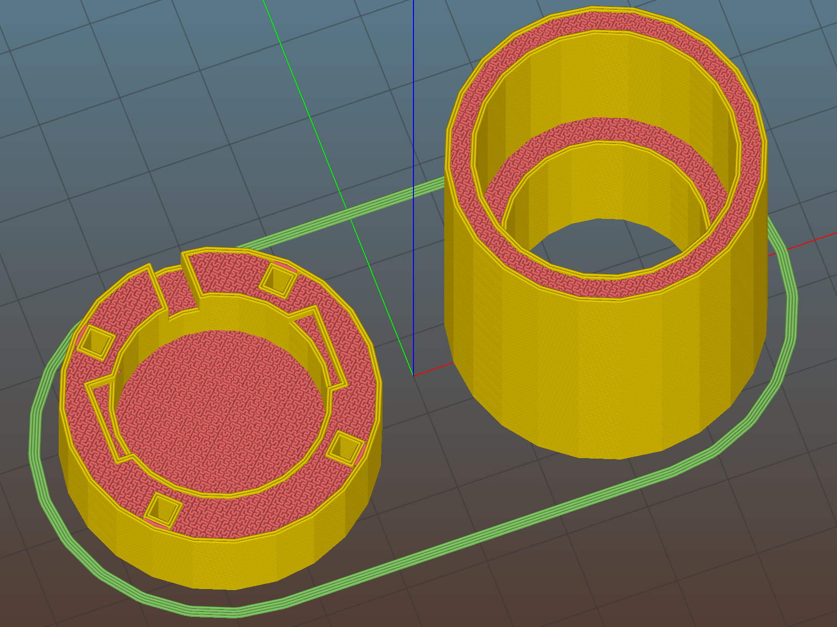
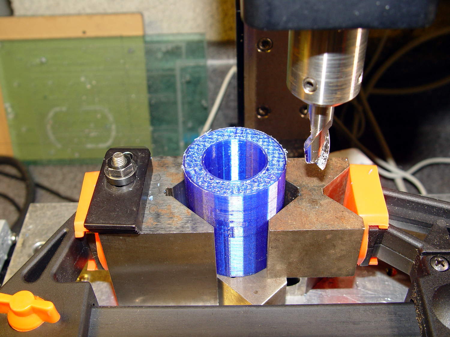
Thinwall open boxes – side detail – 4.98 4.85 measured
Alas, the shutter failed after that image, leaving me with pictures untaken and naught to take them with.
The least-awful alternative seems to be gimmicking up an adapter for a small USB camera from the usual eBay source:
Fashion USB video – case vs camera
The camera’s 640×480 VGA resolution is marginally Good Enough for the purpose, as I can zoom the microscope to completely fill all those pixels. The optics aren’t up to the standard set by the microscope, but we can cope with that for a while.
A bit of doodling & OpenSCAD tinkering produced a suitable adapter:
USB Camera Microscope Mount – solid model
To which Slic3r applied the usual finishing touches:
USB Camera Microscope Mount – Slic3r preview
A bit of silicone tape holds the sloppy focusing thread in place:
USB Camera Microscope Mount – cap with camera
Those are 2-56 screws that will hold the cap onto the tube. I drilled out the clearance holes in the cap and tapped the holes in the eyepiece adapter by hand, grabbing the bits with a pin vise.
Focus the lens at infinity, which in this case meant an old DDJ cover poster on the far wall of the Basement Laboratory, and then it’ll be just as happy with the image coming out of the eyepiece as a human eyeball would be.
I put a few snippets of black electrical tape atop the PCB locating tabs before screwing the tube in place. The tube ID is 1 mm smaller than the PCB OD, in order to hold the PCB perpendicular to the optical axis and clamp it firmly in place. Come to find out that the optical axis of the lens isn’t perfectly perpendicular to the PCB, but it’s close enough for my simple needs.
And then it fits just like you’d expect:
USB Camera Microscope Mount – on eyepiece
Actually, that’s the second version. The distance from the camera lens (equivalently: the PCB below the optical block, which I used as the datum plane) to the eyepiece is a critical dimension that determines whether the image fills the entrance pupil. I guesstimated the first version by hand-holding the camera and measuring with a caliper, tried it out, then iteratively whacked 2 mm off the tube until the image lit up properly:
USB Camera Microscope Mount – adjusting tube length
Minus 4 mm made it slightly too short, but then I could measure the correct position, tweak that dimension in the code, and get another adapter, just like the first one (plus a few other minor changes), except that it worked:
USB Camera Microscope Mount – first light
That’s a screen capture from VLC, which plays from /dev/video0 perfectly. Some manual exposure & color balance adjustment may be in order, but it’s pretty good for First Light.
It turns out that removing the eyepiece and holding the bare sensor over the opening also works fine. The real image from the objective fills much more area than the camera’s tiny sensor: the video image covers about one digit in that picture, but gimmicking up a bare-sensor adapter might be useful.