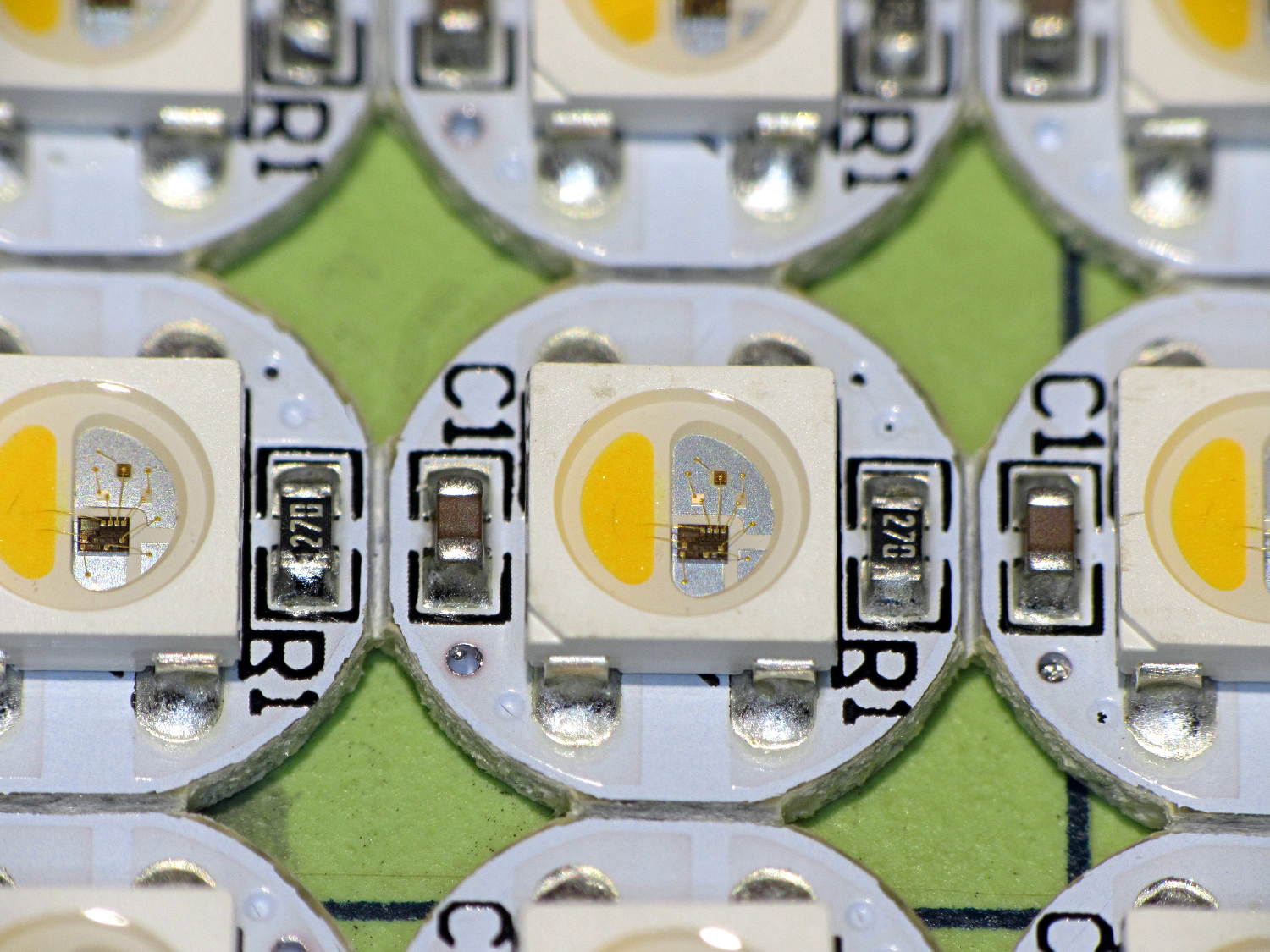
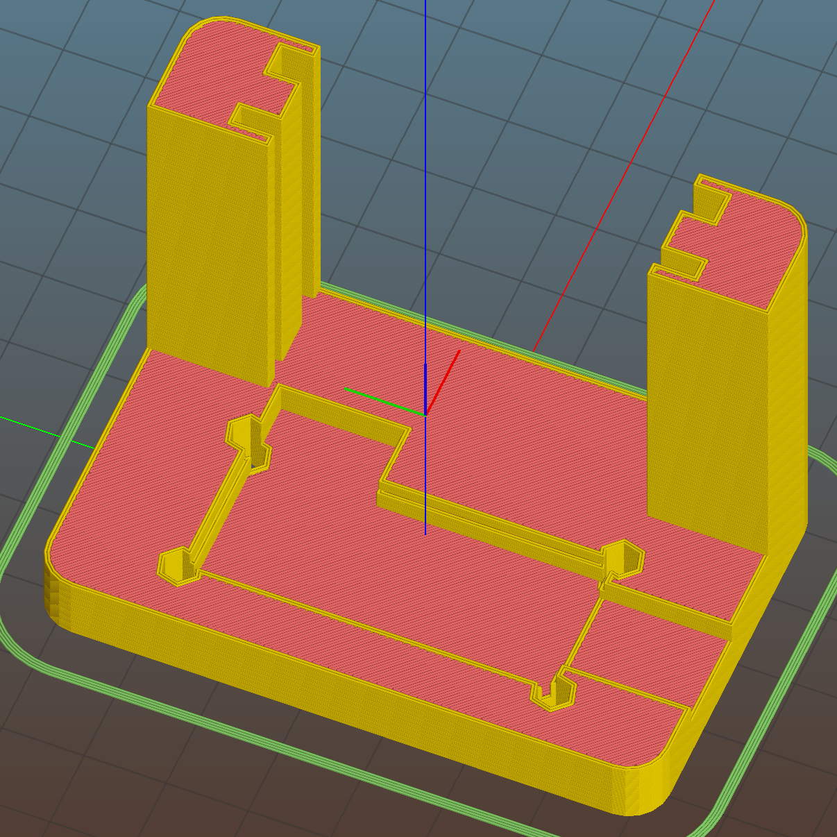
You’ll recall the LED atop the 21HB5A tube failed, shortly after replacing the bottom LED and rewiring the ersatz plate lead, which led me to rebuild the whole thing with SK6812 RGBW LEDs. So I printed all the plastic parts again, because the duodecar tube socket’s pin circle can fit into a hard drive platter’s unmodified 25 mm hole, then drilled another platter to suit:
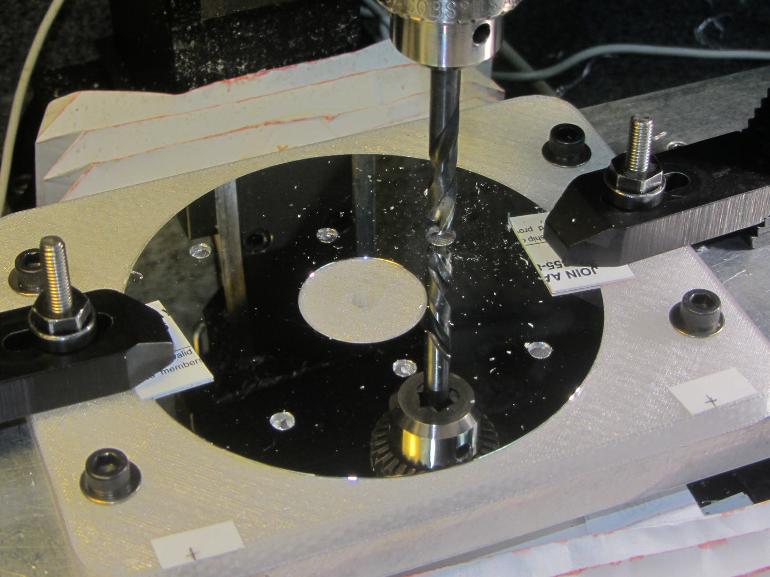
The hole under the drill fits the 3.5 mm stereo socket for the ersatz plate lead, so it’s bigger than before.
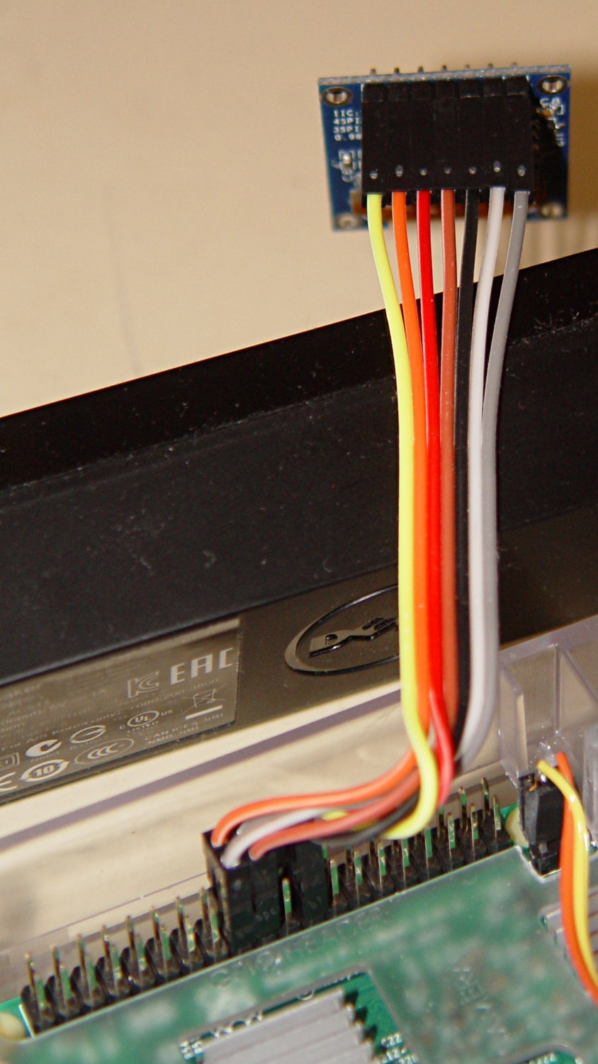
I’ve switched from Arduino Pro Minis with a separate USB converter to Arduino Nanos with an on-board CH340 USB chip, because the fake FTDI chips on the converters are a continuing aggravation:
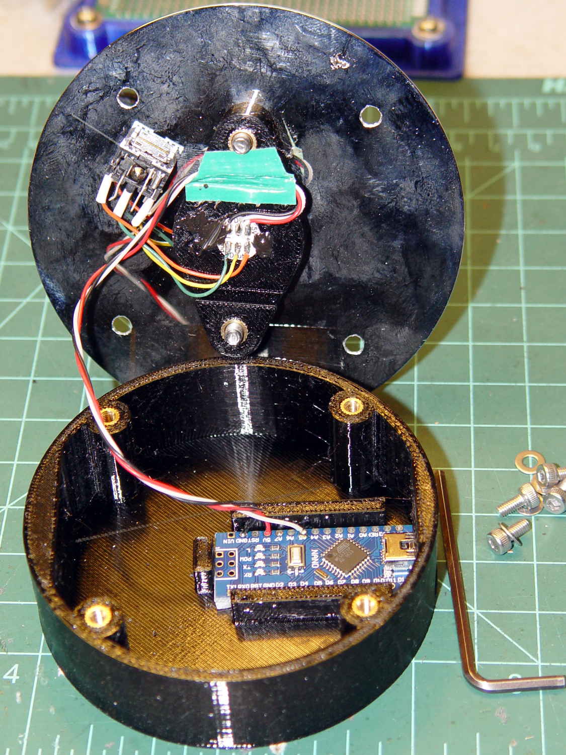
Adding those wire slots to the sockets definitely helps tidy things up; the wires no longer need a crude cable tie anchoring them to the socket mounting screws.
I wanted to drive the LEDs from the A7 pin, rather than the A3 pin I’d been using on the Pro Minis, to keep the wires closer together, but it turns out that A6 and A7 can’t become digital output pins. So I used A5, although I may come to regret the backward incompatibility.
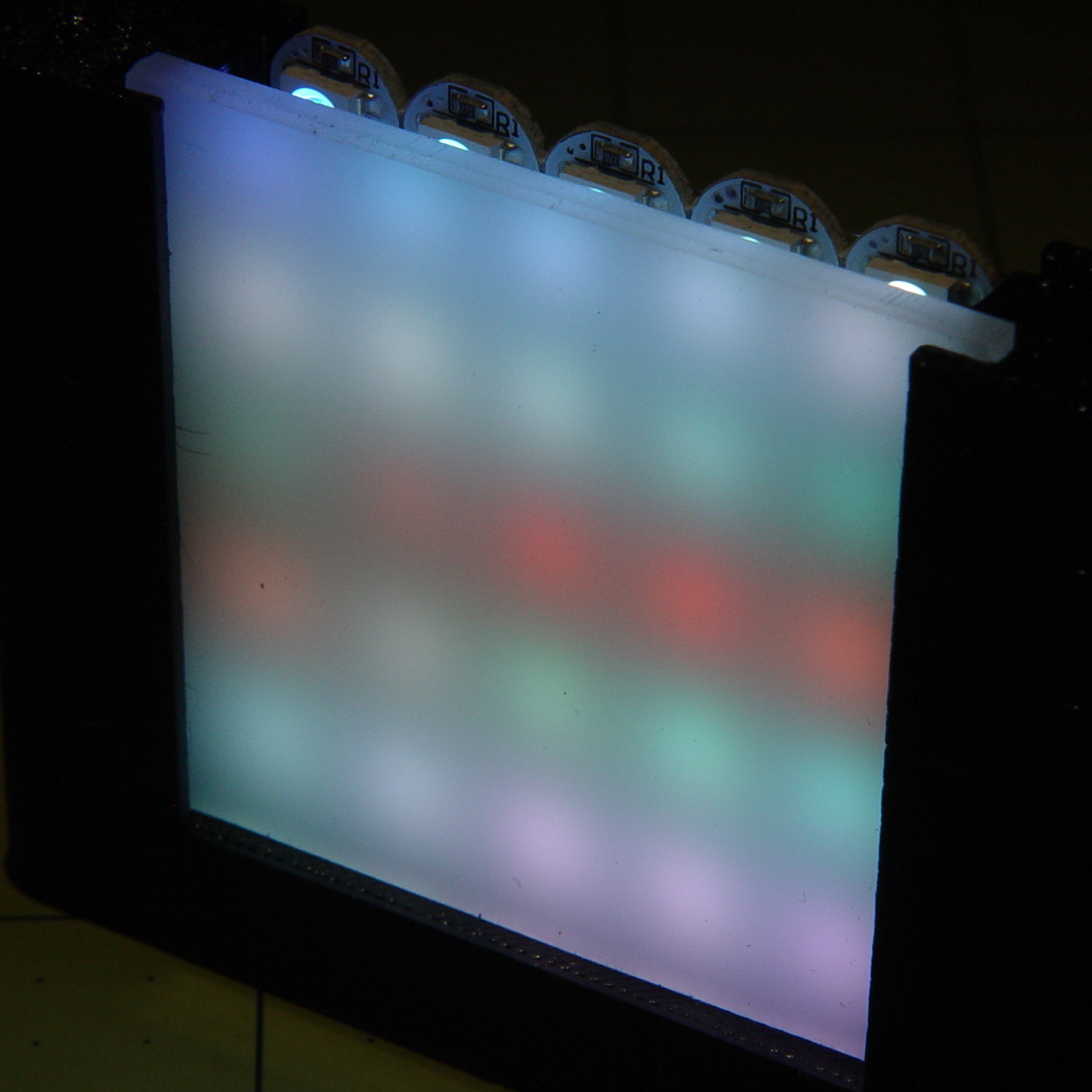
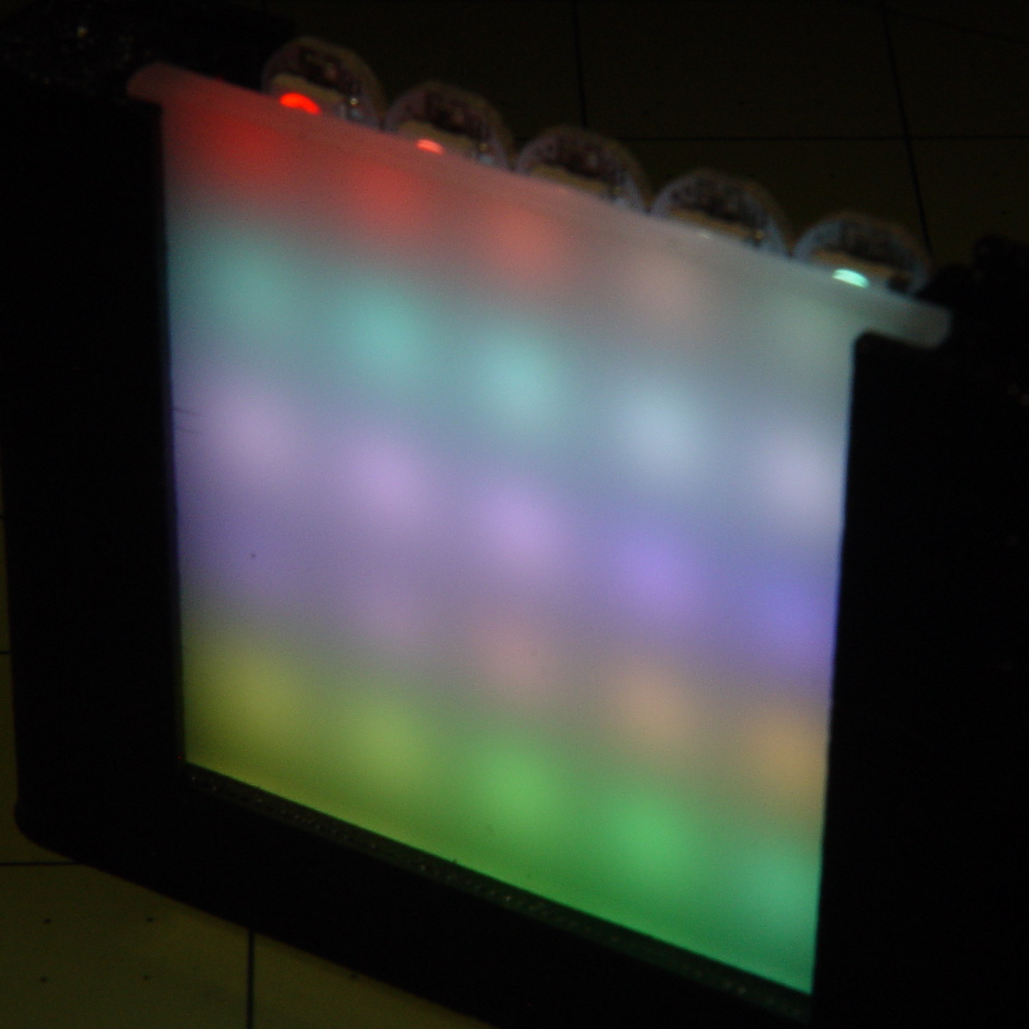
In any event, the 21HB5A tube looks spiffy with its new LEDs in full effect:
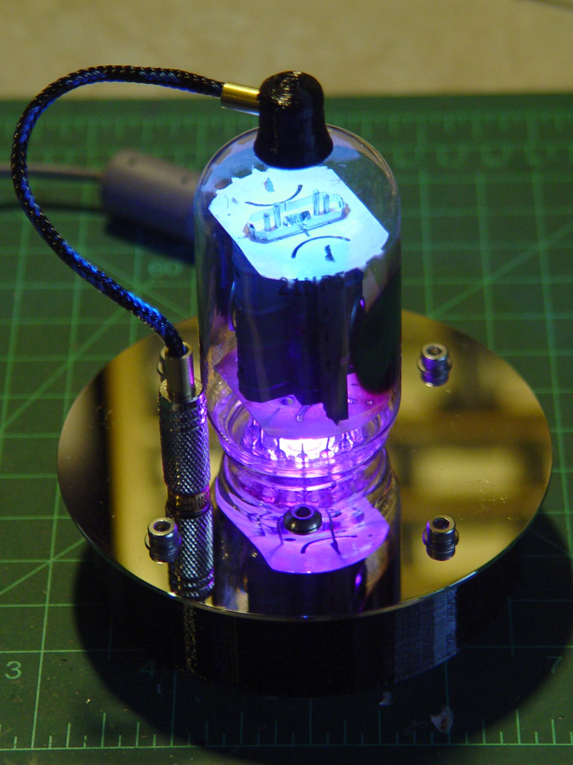
I dialed the white LED PWM down to 32, making the colors somewhat pastel, rather than washed-out.
The Arduino source code as a GitHub Gist:
| // Neopixel mood lighting for vacuum tubes | |
| // Ed Nisley – KE4ANU – June 2016 | |
| // September 2016 – Add Morse library and blinkiness | |
| // October 2016 – Set random colors at cycle end | |
| // March 2017 – RGBW SK6812 LEDs | |
| #include <Adafruit_NeoPixel.h> | |
| #include <morse.h> | |
| #include <Entropy.h> | |
| //———- | |
| // Pin assignments | |
| const byte PIN_NEO = A5; // DO – data out to first Neopixel | |
| const byte PIN_HEARTBEAT = 13; // DO – Arduino LED | |
| #define PIN_MORSE 12 | |
| //———- | |
| // Constants | |
| // number of pixels | |
| #define PIXELS 2 | |
| // index of the Morse output pixel and how fast it sends | |
| boolean Send_Morse = false; | |
| #define PIXEL_MORSE (PIXELS – 1) | |
| #define MORSE_WPM 10 | |
| // lag between adjacent pixel, degrees of slowest period | |
| #define PIXELPHASE 45 | |
| // update LEDs only this many ms apart (minus loop() overhead) | |
| #define UPDATEINTERVAL 50ul | |
| #define UPDATEMS (UPDATEINTERVAL – 1ul) | |
| // number of steps per cycle, before applying prime factors | |
| #define RESOLUTION 500 | |
| //———- | |
| // Globals | |
| // instantiate the Neopixel buffer array | |
| Adafruit_NeoPixel strip = Adafruit_NeoPixel(PIXELS, PIN_NEO, NEO_GRBW + NEO_KHZ800); | |
| uint32_t FullWhite = strip.Color(255,255,255,255); | |
| uint32_t FullOff = strip.Color(0,0,0,0); | |
| uint32_t MorseColor; | |
| struct pixcolor_t { | |
| unsigned int Prime; | |
| unsigned int NumSteps; | |
| unsigned int Step; | |
| float StepSize; | |
| float Phase; | |
| byte MaxPWM; | |
| }; | |
| unsigned int PlatterSteps; | |
| byte PrimeList[] = {3,5,7,13,19,29}; | |
| // colors in each LED | |
| enum pixcolors {RED, GREEN, BLUE, WHITE, PIXELSIZE}; | |
| struct pixcolor_t Pixels[PIXELSIZE]; // all the data for each pixel color intensity | |
| uint32_t UniColor; | |
| unsigned long MillisNow; | |
| unsigned long MillisThen; | |
| // Morse code | |
| char * MorseText = " cq cq cq de ke4znu"; | |
| LEDMorseSender Morse(PIN_MORSE, (float)MORSE_WPM); | |
| uint8_t PrevMorse, ThisMorse; | |
| //– Figure PWM based on current state | |
| byte StepColor(byte Color, float Phi) { | |
| byte Value; | |
| Value = (Pixels[Color].MaxPWM / 2.0) * (1.0 + sin(Pixels[Color].Step * Pixels[Color].StepSize + Phi)); | |
| // Value = (Value) ? Value : Pixels[Color].MaxPWM; // flash at dimmest points for debug | |
| return Value; | |
| } | |
| //– Select three unique primes for the color generator function | |
| // Then compute all the step parameters based on those values | |
| void SetColorGenerators(void) { | |
| Pixels[RED].Prime = PrimeList[random(sizeof(PrimeList))]; | |
| do { | |
| Pixels[GREEN].Prime = PrimeList[random(sizeof(PrimeList))]; | |
| } while (Pixels[RED].Prime == Pixels[GREEN].Prime); | |
| do { | |
| Pixels[BLUE].Prime = PrimeList[random(sizeof(PrimeList))]; | |
| } while (Pixels[BLUE].Prime == Pixels[RED].Prime || | |
| Pixels[BLUE].Prime == Pixels[GREEN].Prime); | |
| do { | |
| Pixels[WHITE].Prime = PrimeList[random(sizeof(PrimeList))]; | |
| } while (Pixels[WHITE].Prime == Pixels[RED].Prime || | |
| Pixels[WHITE].Prime == Pixels[GREEN].Prime || | |
| Pixels[WHITE].Prime == Pixels[BLUE].Prime); | |
| printf("Primes: %d %d %d %d\r\n",Pixels[RED].Prime,Pixels[GREEN].Prime,Pixels[BLUE].Prime,Pixels[WHITE].Prime); | |
| Pixels[RED].MaxPWM = 255; | |
| Pixels[GREEN].MaxPWM = 255; | |
| Pixels[BLUE].MaxPWM = 255; | |
| Pixels[WHITE].MaxPWM = 32; | |
| unsigned int PhaseSteps = (unsigned int) ((PIXELPHASE / 360.0) * | |
| RESOLUTION * (unsigned int) max(max(max(Pixels[RED].Prime,Pixels[GREEN].Prime),Pixels[BLUE].Prime),Pixels[WHITE].Prime)); | |
| printf("Pixel phase offset: %d deg = %d steps\r\n",(int)PIXELPHASE,PhaseSteps); | |
| for (byte c=0; c < PIXELSIZE; c++) { | |
| Pixels[c].NumSteps = RESOLUTION * Pixels[c].Prime; // steps per cycle | |
| Pixels[c].StepSize = TWO_PI / Pixels[c].NumSteps; // radians per step | |
| Pixels[c].Step = random(Pixels[c].NumSteps); // current step | |
| Pixels[c].Phase = PhaseSteps * Pixels[c].StepSize;; // phase in radians for this color | |
| printf(" c: %d Steps: %d Init: %d Phase: %d deg",c,Pixels[c].NumSteps,Pixels[c].Step,(int)(Pixels[c].Phase * 360.0 / TWO_PI)); | |
| printf(" PWM: %d\r\n",Pixels[c].MaxPWM); | |
| } | |
| } | |
| //– Helper routine for printf() | |
| int s_putc(char c, FILE *t) { | |
| Serial.write(c); | |
| } | |
| //—————— | |
| // Set the mood | |
| void setup() { | |
| pinMode(PIN_HEARTBEAT,OUTPUT); | |
| digitalWrite(PIN_HEARTBEAT,LOW); // show we arrived | |
| Serial.begin(57600); | |
| fdevopen(&s_putc,0); // set up serial output for printf() | |
| printf("Vacuum Tube Mood Light – RGBW\r\nEd Nisley – KE4ZNU – March 2017\r\n"); | |
| Entropy.initialize(); // start up entropy collector | |
| // set up pixels | |
| strip.begin(); | |
| strip.show(); | |
| // lamp test: a brilliant white flash | |
| printf("Lamp test: flash white\r\n"); | |
| for (byte i=0; i<5 ; i++) { | |
| for (int j=0; j < strip.numPixels(); j++) { // fill LEDs with white | |
| strip.setPixelColor(j,FullWhite); | |
| } | |
| strip.show(); | |
| delay(500); | |
| for (int j=0; j < strip.numPixels(); j++) { // fill LEDs with black | |
| strip.setPixelColor(j,FullOff); | |
| } | |
| strip.show(); | |
| delay(500); | |
| } | |
| // get an actual random number | |
| uint32_t rn = Entropy.random(); | |
| printf("Random seed: %08lx\r\n",rn); | |
| randomSeed(rn); | |
| // set up the color generators | |
| SetColorGenerators(); | |
| // set up Morse generator | |
| Morse.setup(); | |
| Morse.setMessage(String(MorseText)); | |
| MorseColor = strip.Color(255,random(32,64),random(16),0); | |
| PrevMorse = ThisMorse = digitalRead(PIN_MORSE); | |
| printf("Morse enabled: %d at %d wpm color: %08lx\n [%s]\r\n",Send_Morse,MORSE_WPM,MorseColor,MorseText); | |
| MillisNow = MillisThen = millis(); | |
| } | |
| //—————— | |
| // Run the mood | |
| void loop() { | |
| if (!Morse.continueSending()) { | |
| printf("Restarting Morse message\r\n"); | |
| Morse.startSending(); | |
| } | |
| ThisMorse = digitalRead(PIN_MORSE); | |
| MillisNow = millis(); | |
| if (((MillisNow – MillisThen) >= UPDATEMS) || // time for color change? | |
| (PrevMorse != ThisMorse)) { // Morse output bit changed? | |
| digitalWrite(PIN_HEARTBEAT,HIGH); | |
| if (Send_Morse && ThisMorse) { // if Morse output high, overlay flash | |
| strip.setPixelColor(PIXEL_MORSE,MorseColor); | |
| } | |
| PrevMorse = ThisMorse; | |
| strip.show(); // send out precomputed colors | |
| boolean CycleRun = false; // check to see if all cycles have ended | |
| for (byte c=0; c < PIXELSIZE; c++) { // compute next increment for each color | |
| if (++Pixels[c].Step >= Pixels[c].NumSteps) { | |
| Pixels[c].Step = 0; | |
| printf("Cycle %d steps %d at %8ld delta %ld ms\r\n",c,Pixels[c].NumSteps,MillisNow,(MillisNow – MillisThen)); | |
| } | |
| else { | |
| CycleRun = true; // this color is still cycling | |
| } | |
| } | |
| // If all cycles have completed, reset the color generators | |
| if (!CycleRun) { | |
| printf("All cycles ended: setting new color generator values\r\n"); | |
| SetColorGenerators(); | |
| } | |
| for (int i=0; i < strip.numPixels(); i++) { // for each pixel | |
| byte Value[PIXELSIZE]; | |
| for (byte c=0; c < PIXELSIZE; c++) { // … for each color | |
| Value[c] = (Pixels[c].MaxPWM / 2.0) * (1.0 + sin(Pixels[c].Step * Pixels[c].StepSize – i*Pixels[c].Phase)); | |
| } | |
| UniColor = strip.Color(Value[RED],Value[GREEN],Value[BLUE],Value[WHITE]); | |
| strip.setPixelColor(i,UniColor); | |
| } | |
| MillisThen = MillisNow; | |
| digitalWrite(PIN_HEARTBEAT,LOW); | |
| } | |
| } |