The Smell of Molten Projects in the Morning

Ed Nisley's Blog: Shop notes, electronics, firmware, machinery, 3D printing, laser cuttery, and curiosities. Contents: 100% human thinking, 0% AI slop.

Category: Electronics Workbench

Electrical & Electronic gadgets

  • AD8310 Log Amp Module: LF Response

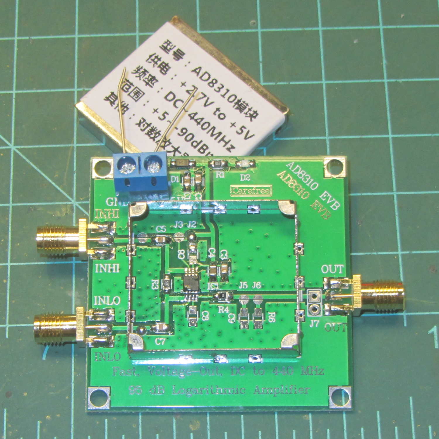
    The label atop a generic AD8310 Log Amp module seemed unambiguous:

    AD8310 Log Amp module - overview
    AD8310 Log Amp module – overview

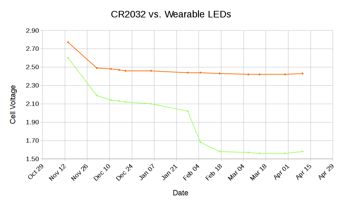
    Firing the HP 8591 tracking generator into the InHi SMA, terminating InLo (not shown above, for reasons you’ll see below), connecting the Out SMA to the scope’s Trace 1, and the spectrum analyzer’s sweep output to Trace 2 produced an oddity:

    AD8310 Log Amp - 100 kHz 500 MHz
    AD8310 Log Amp – 100 kHz 500 MHz

    The upward-sloping ramp (lower trace) shows the HP 8591’s horizontal sweep, with the tracking generator tuning from 100 kHz to 500 MHz during the 20 ms sweep. The log amp output (upper trace) drops more-or-less linearly with increasing frequency, which seems odd. The tracking generator signal should be pretty much level and the log amp’s output should be more-or-less flat.

    My oscilloscope tops out at 150 MHz. The displayed RF is down by 3 dB = 0.6 div at 1.5 division = 190 MHz into the sweep:

    AD8310 Log Amp - 100 kHz 500 MHz - RF 50 ohm term
    AD8310 Log Amp – 100 kHz 500 MHz – RF 50 ohm term

    However, the RF looks pretty much flat up to 125 MHz and it’s still visible beyond 400 MHz, so I think the tracking generator is doing what it’s supposed to. If the RF were decreasing, then the trace would look different, methinks.

    The response to a 60 kHz sine wave doesn’t look quite right:

    AD8310 Log Amp - 60 kHz 1 Vpk
    AD8310 Log Amp – 60 kHz 1 Vpk

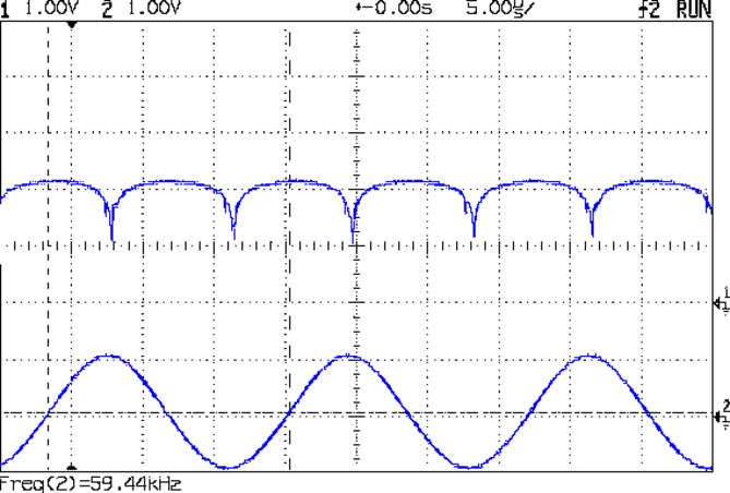
    Eyeballometrically, it might be a log response to the absolute value of the derivative: kinda flat on the ups-and-downs, kinda zero-ish at the tops-and-bottoms. Or maybe it’s the log response to a phase-shifted version of the input, with the lows corresponding to the zero crossings.

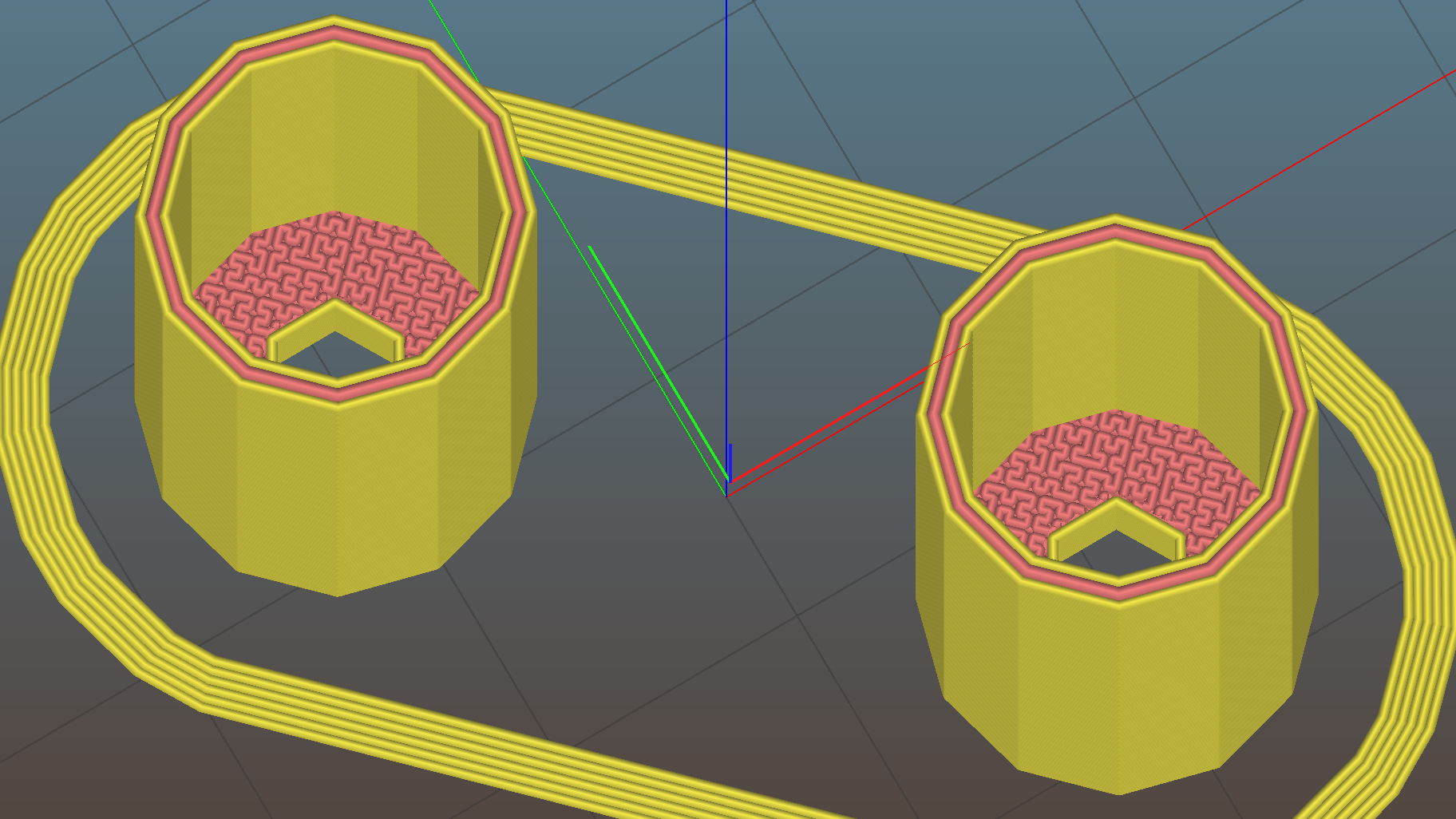
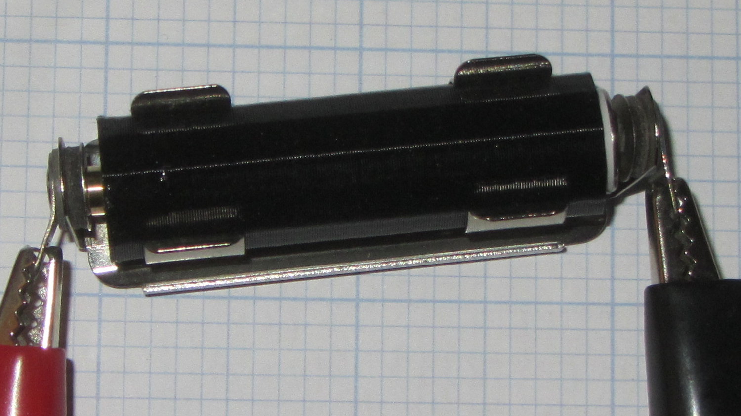
    Documentation for the circuit seems nonexistent, because eBay. Fortunately, one can pop the top to reveal the straightforward PCB layout:

    AD8310 Log Amp module - uncovered
    AD8310 Log Amp module – uncovered

    A closer look:

    AD8310 Log Amp module - PCB detail
    AD8310 Log Amp module – PCB detail

    A capacitance meter says input capacitors C5 and C7 are both 10 nF.

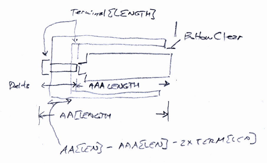
    A sketch of the circuitry:

    AD8310 Log Amp module - input circuit
    AD8310 Log Amp module – input circuit

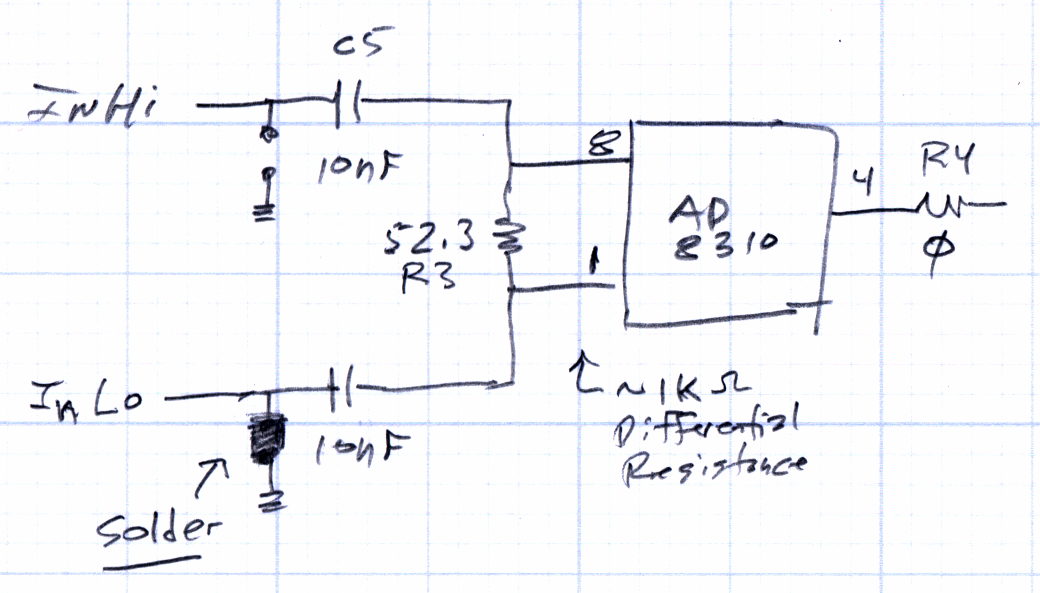
    The datasheet puts the terminating resistor on the other side of the input caps, where it surely belongs:

    AD8310 Datasheet - Basic Connections diagram
    AD8310 Datasheet – Basic Connections diagram


    Achtung: the solder blob just to the left of C7 grounds the signal pin on the InLo SMA. Don’t connect anything to InLo which might take offense at having its output shorted to ground; the SMA terminator I used had no effect whatsoever.

    The AD8310 chip (assuming that’s what it really is) has a differential input resistance = 1 kΩ and capacitance = 1.4 pF in parallel with R3, the 52.3 Ω terminating resistor, making the net resistance just under 50 Ω.

    At 60 kHz, the input caps have a reactance of 270 Ω apiece, which means the “terminating” resistor is maybe 10% of the mostly capacitive input impedance seen at the InHi connector. That means the AD8310 inputs see maybe 10% of the input signal.

    In fact, if you regard those three parts as an RC high pass filter and merge the caps into a single 5 nF unit, it rolls off at 620 kHz = 1/(2π · 52 · 5 pF). Obviously, it’ll be a fine differentiator at 1/10 the breakpoint frequency.

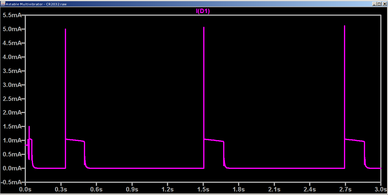
    A simulation shows it in action (clicky for more dots):

    AD8310 Log Amp module - input circuit simulation
    AD8310 Log Amp module – input circuit simulation

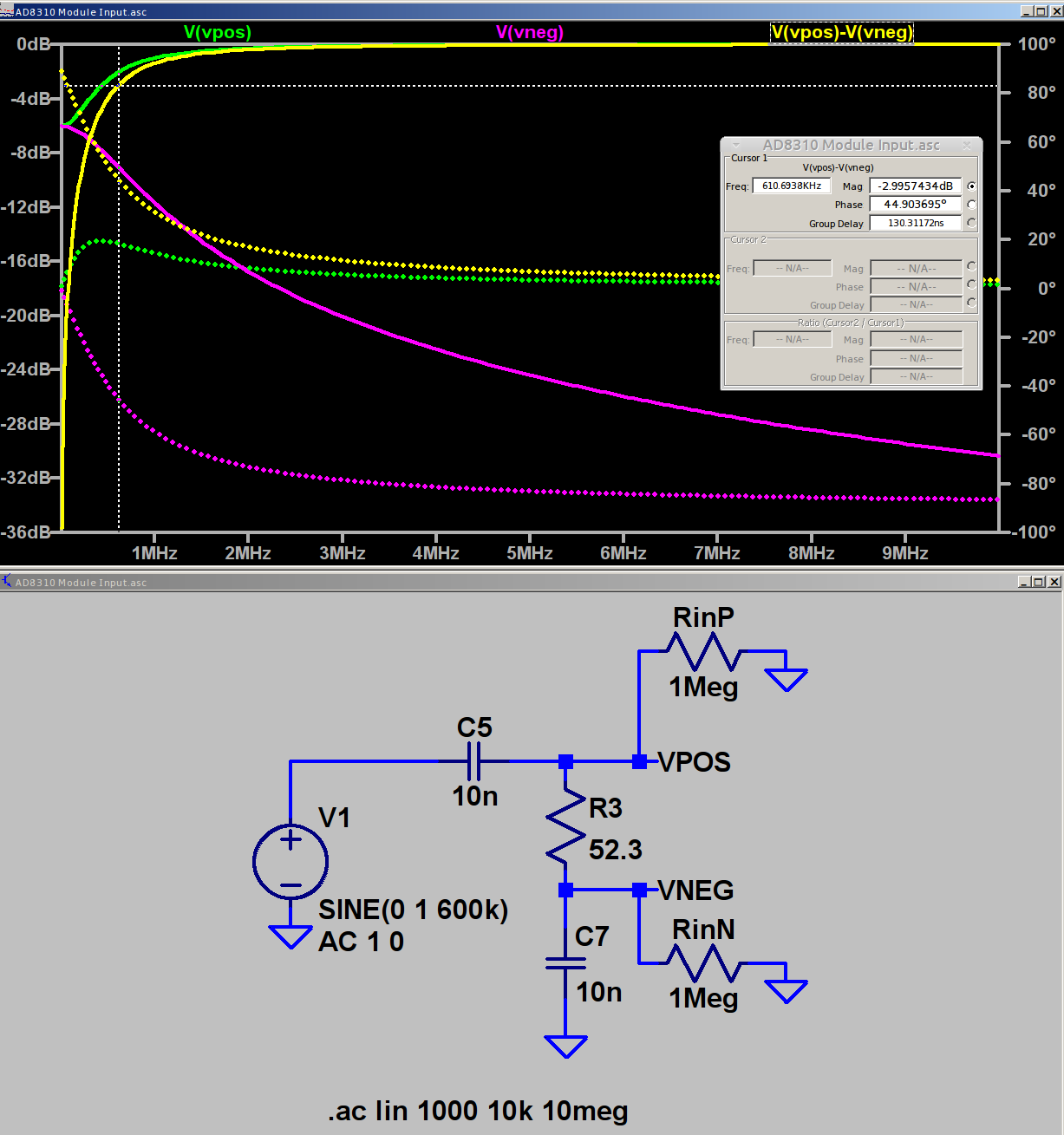
    The two 1 MΩ resistors provide a balanced DC path-to-ground for R3 to keep the simulator happy.

    The (+) input tends toward 0 dB as C5 tends toward a short, the (-) input tends toward ground as C7 does likewise, but their difference isn’t a constant value. Seeing as how a log amp should respond to small differences, methinks it’s hard at work.

    The AD8310 data sheet says the scale factor is about 24 mV/dB between 10 MHz and 200 MHz, with no frequency dependence worth mentioning. Eyeballometrically, the output has a 240 mV = 10 dB straight-line decrease over the entire frequency range of that scope shot. It drops by 220 mV = 9.2 dB in the decade from 50 to 500 MHz, half of the 20 dB you’d expect from a first-order filter response.

    The AD8310 has an internal 2 MHz high pass feedback loop to suppress low frequency input offset voltages. The doc recommends a 1 µF cap from OLFT to ground for frequencies down in the low audio range. One might solder the cap across the convenient pads labeled C8 below the chip.

    Rearranging the input circuitry seems in order:

    • Move R3 outside C5 and C7, per the datasheet
    • Increase C5 and C7 to 1 µF -ish
    • Add 100nF – 1 µF bypass cap at C8

    I have the uneasy feeling I’m overlooking something obvious …

    Update – The rest of the story: Corrected Input Circuit and Video Bandwidth Rolloff.

  • Arduino Joystick

    A bag of sub-one-dollar resistive joysticks arrived from halfway around the planet:

    Arduino UNO - resistive joystick
    Arduino UNO – resistive joystick

    A quick-and-dirty test routine showed the sticks start out close to VCC/2:

    Welcome to minicom 2.7
    
    OPTIONS: I18n
    Compiled on Feb  7 2016, 13:37:27.
    Port /dev/ttyACM0, 10:23:45
    
    Press CTRL-A Z for help on special keys
    
    Joystick exercise
    Ed Nisley - KE4ZNU - May 2017
    00524 - 00513 - 1
    

    That’s from minicom on the serial port, as the Arduino IDE’s built-in serial monitor ignores bare Carriage Return characters.

    The joystick hat tilts ±25° from its spring-loaded center position, but the active region seems to cover only 15° of that arc, with a 5° dead zone around the center and 5° of overtravel at the limits. This is not a high-resolution instrument intended for fine motor control operations.

    The analog input values range from 0x000 to 0x3FF across the active region. Aim the connector at your tummy to make the axes work the way you’d expect: left / down = minimum, right / up = maximum.

    The delay(100) statements may or may not be needed for good analog input values, depending on some imponderables that seem not to apply for this lashup, but they pace the loop() to a reasonable update rate.

    Pushing the hat toward the PCB activates the simple switch you can see in the picture. It requires an external pullup resistor (hence the INPUT_PULLUP configuration) and reports low = 0 when pressed.

    Those are 0.125 inch (exactly!) holes on a 19.5×26.25 mm grid in a 26.5×34.25 mm PCB. Makes no sense to me, either.

    The trivial Arduino source code as a GitHub Gist:

    // Joystick exercise
    #define JOYX A0
    #define JOYY A1
    #define BUTTON 7
    int JoyX,JoyY;
    boolean Button;
    //– Helper routine for printf()
    int s_putc(char c, FILE *t) {
    Serial.write(c);
    }
    void setup() {
    Serial.begin (9600);
    fdevopen(&s_putc,0); // set up serial output for printf()
    Serial.println ("Joystick exercise");
    Serial.println ("Ed Nisley – KE4ZNU – May 2017");
    pinMode(BUTTON,INPUT_PULLUP);
    }
    void loop() {
    JoyX = analogRead(JOYX);
    delay(100);
    JoyY = analogRead(JOYY);
    delay(100);
    Button = digitalRead(BUTTON);
    printf("%05d – %05d – %1d\r",JoyX,JoyY,Button);
    }
  • Wearable LED vs. Astable Multivibrator vs. Dead Lithium Cells

    Mashing the wearable LED from the completely dead CR2032 cell with a classic astable multivibrator circuit and a not-dead-yet CR123 cell produced a pure-analog desktop blinky:

    CR123A Astable - front
    CR123A Astable – front

    Of course, I managed to swap the base resistors, which meant the LED stayed on most of the time, which accounts for the slightly off-kilter brown resistor just under the LED.

    It doesn’t look like much with the LED off:

    CR123A Astable - top - off
    CR123A Astable – top – off

    Running from a 2.8 V (= dead) lithium cell, the LED lights a dark room at 3 mA:

    CR123A Astable - top - on
    CR123A Astable – top – on

    The LTSpice schematic gives the details:

    Astable Multivibrator - CR2032 - schematic
    Astable Multivibrator – CR2032 – schematic

    The LED definitely didn’t come from Nichia and the 2N3704 transistors aren’t the 2N3904s found in the LTSpice library, but, by and large, this is the kind of circuit where nearly anything will work.

    The actual LED current obviously depends critically on the particular LED and the cell voltage, so this represents more of a serving suggestion than an actual prediction:

    Astable Multivibrator - CR2032 - waveform
    Astable Multivibrator – CR2032 – waveform

    Indeed, a Tek current probe clamped around one of those 10 AWG copper wires shows a much more enthusiastic LED current (1 mA/div):

    Astable - CR123A 2.8 V - 1 mA -green
    Astable – CR123A 2.8 V – 1 mA -green

    I don’t trust the baseline very much. The simulation & back of the envelope agree: the LED-off current should be around 400 µA (which doesn’t depend on the LED at all), so it’s in the right ballpark.

    Your mileage will definitely differ.

    It runs without a trace of software, which everybody at Squidwrench thought was wonderful …

  • Monthly Science: CR2023 Lithium Cells vs. Wearable LEDs

    Those wearable LEDs spent the last five months sitting on the kitchen window sash, quietly discharging their CR2032 lithium cells:

    Wearable LED with CR2023 cell
    Wearable LED with CR2023 cell

    Occasional voltage measurements produced an interesting graph:

    CR2032 vs Wearable LEDs
    CR2032 vs Wearable LEDs

    CR2023 primary lithium cells start out around 3.3 V, so these were pretty much dead (from their previous lives in dataloggers) when I slipped them into their holders. The LEDs seem to be blue LEDs, with threshold voltages around 3.6 V, with colored phosphors / filters, so they started out dim and got dimmer. The green(-ish) LED obviously fell over a cliff and went dark in late January; I have no way to measure long-term microamp currents, alas.

    The reddish LED is still going, mmm, strong.

    If you need a rather dim light for a surprisingly long time, these things will do the trick.

    I should gimmick up another astable multivibrator to blink one LED.

    The original data:

    CR2032 vs Wearable LEDs - data
    CR2032 vs Wearable LEDs – data
  • Eneloop AAA Cells: First Charge

    With an AAA-to-AA adapter in hand, the Eneloop AAA cells looked like this:

    Eneloop AAA - as received - Ah scale - 2017-04-20
    Eneloop AAA – as received – Ah scale – 2017-04-20

    The glitch comes from a not-quite-seated cell, showing that a poor connection matters.

    The package touts “up to 800 mA·h, 750 mA·h min”, with asterisks and superscripts leading to “Based on IEC 61951-2(7.3.2)“, access to which requires coughing up 281 bucks. So it goes.

    A full charge made them happier:

    Eneloop AAA - first charge - Ah scale - 2017-04-22
    Eneloop AAA – first charge – Ah scale – 2017-04-22

    The as-delivered 530 mA·h capacity represents 73% of the 725 mA·h after the first charge, so I suppose they’re more-or-less within the “Maintains up to 70% charge after 10 years of storage” claim. The 16-10 date code suggests they’re hot off the factory charger, so they must ship with somewhat less than a full charge.

    Comparing the capacity in W·h makes more sense, because most devices (other than the Planet Bike blinky light these will go into, of course) use a boost converter to get a fixed voltage from the declining terminal voltage.

    They arrived bearing just over 600 mW·h:

    Eneloop AAA - as received - Wh scale - 2017-04-20
    Eneloop AAA – as received – Wh scale – 2017-04-20

    After charging, that went a bit over 850 mW·h :

    Eneloop AAA - first charge - Wh scale - 2017-04-22
    Eneloop AAA – first charge – Wh scale – 2017-04-22

    Call it 71% of full capacity on arrival. Close enough.

    The Planet Bike blinky will be somewhat dimmer with two NiMH cells delivering 2.3-ish V, compared with the initial 3-ish V from a pair of alkaline cells. I generally burn the alkalines down to 1.1 V apiece, so perhaps they’ll be Good Enough.

    Now, if I were gutsy, I’d install a rechargeable lithium AAA cell, with a dummy pass-through adapter in the other cell socket, and run the blinky at 3.7 V. At least for a few moments, anyhow …

  • Cylindrical Cell Adapters

    An octet of Eneloop AAA cells arrived, I wanted to measure their as-delivered charge (the package says “Factory Charged With SOLAR ENERGY”, so you know it’s good), and discovered I’d given away my AAA cell holders. You can actually get inter-series adapters on eBay, but what’s the fun in that? Plus, I didn’t want to delay gratification for a month; you know how it is.

    Soooo:

    AAA to AA Adapter - top - Slic3r
    AAA to AA Adapter – top – Slic3r

    It’s basically an AA-size sleeve that fits over the AAA cell, with a lathe-turned brass post conducting juice from the + terminal of the inner cell outward:

    AAA to AA Adapter - parts
    AAA to AA Adapter – parts

    Not much to look at when it’s assembled:

    AAA to AA Adapter - assembled
    AAA to AA Adapter – assembled

    The AAA cell fits deliberately loose, because this goes into a metal clip holding everything firmly in place for the battery tester:

    AAA to AA Adapter - in use
    AAA to AA Adapter – in use

    The source code tabulates the sizes of several cylindrical cells, exactly zero other pairs of which have been tested; I expect most won’t work correctly. In particular, the table entries should include the contact button OD and thickness for each cell, so that I can turn out the proper terminal for each pair of cells. If I ever need a different adapter, I’ll beat some cooperation out of that, too.

    Discovered I needed an adapter after breakfast, started testing cells after lunch. Life is good!

    The OpenSCAD source code as a GitHub Gist:

    // Cylindrical cell adapters
    // Ed Nisley KE4ZNU April 2017
    //- Extrusion parameters must match reality!
    ThreadThick = 0.25;
    ThreadWidth = 0.40;
    HoleWindage = 0.2;
    Protrusion = 0.1; // make holes end cleanly
    inch = 25.4;
    function IntegerMultiple(Size,Unit) = Unit * ceil(Size / Unit);
    //———————-
    // Dimensions
    OutCell = "AA"; // cell sizes
    InCell = "AAA";
    BottomClear = 3*ThreadThick; // shorten outer shell to allow base protrusion
    Terminal = [3.0,4.0,2.0]; // terminal: OD = nub dia, length = nub thickness
    NAME = 0;
    ID = 0; // for non-cell cylinders
    OD = 1;
    LENGTH = 2;
    Cells = [
    ["AAAA",8.3,42.5],
    ["AAA",10.5,44.5],
    ["AA",14.5,50.5],
    ["C",26.2,50],
    ["D",34.2,61.5],
    ["A23",10.3,28.5],
    ["CR123",17.0,34.5],
    ["18650",18.6,65.2]
    ];
    Outer = search([OutCell],Cells,1,0)[0];
    Inner = search([InCell],Cells,1,0)[0];
    echo(str("Outer cell: ",Cells[Outer][NAME]));
    echo(str("Inner cell: ",Cells[Inner][NAME]));
    echo(str("Wall: ",Cells[Outer][OD] – (Cells[Inner][OD]/cos(180/NumSides) + 2*ThreadWidth)));
    Delta = Cells[Outer][LENGTH] – Cells[Inner][LENGTH];
    echo(str("Terminal OAL: ",Delta));
    echo(str(" … head: ",Terminal[LENGTH]));
    echo(str(" … shaft: ",Delta – Terminal[LENGTH]));
    NumSides = 3*4;
    //———————-
    // Useful routines
    module PolyCyl(Dia,Height,ForceSides=0) { // based on nophead's polyholes
    Sides = (ForceSides != 0) ? ForceSides : (ceil(Dia) + 2);
    FixDia = Dia / cos(180/Sides);
    cylinder(r=(FixDia + HoleWindage)/2,h=Height,$fn=Sides);
    }
    //———————-
    // Construct adapter
    module Adapter() {
    difference() {
    cylinder(d=Cells[Outer][OD],
    h=Cells[Outer][LENGTH] – BottomClear – Terminal[LENGTH],
    $fn=NumSides);
    translate([0,0,Delta – Terminal[LENGTH]])
    PolyCyl(Cells[Inner][OD] + 2*ThreadWidth,
    Cells[Inner][LENGTH] + Protrusion,
    NumSides);
    translate([0,0,-Protrusion])
    PolyCyl(Terminal[ID],
    2*Cells[Outer][LENGTH],
    6);
    }
    }
    //———————-
    // Build it
    Adapter();

    The original doodle:

    AAA to AA Adapter - sketch
    AAA to AA Adapter – sketch
  • 3D Printer Design Conversation: Part 5

    The final installment of musings about building a large-format 3D printer …

    (Continued from yesterday)

    Perhaps they saw your blog post?

    The old-old (original) high-resistance Kysan motor costs something like $45 and, apart from minor cosmetic differences, looks /exactly/ the same as the old-new low-resistance motor. If you were picking motors and didn’t quite understand why you needed a low-resistance winding, which would you pick? Hence, my insistence on knowing the requirements before plunking down your money.

    To be fair, I didn’t understand that problem until the Thing-O-Matic rubbed my nose in it. With all four motors. Vigorously.

    So, yeah, I think I had a part in that.

    comes back to the same numbers over and over

    The new-new leadscrews have something like half the pitch of the old-new and old-old threads; I don’t recall the number offhand. In any event, that gives you twice the number of motor steps per millimeter of motion and roughly twice the lifting force. This is pretty much all good, even though it may reduce the maximum Z axis speed (depends on your settings & suchlike).

    When it moves upward by, say, 5 mm and downward by 5 mm, you’re measuring position repeatability. That level of repeatability is pretty much a given (for the M2, anyhow), but it doesn’t involve stiction & suchlike.

    Can you move the platform up by 0.01 mm, then down by 0.01 mm, and measure 0.01 mm change after each motion?

    Do larger increments track equally well in both directions?

    Move upward a few millimeters, then step downward by 0.01 mm per step. Does the measurement increase by 0.01 mm after each step?

    Repeat that by moving downward, then upward in 0.01 mm increments.

    If the platform moves without backlash & stiction in both directions with those increments, it’s a definite improvement.

    I wish I knew more
    everything you learned is burned into your head forever

    The way to learn more is exactly what you’re doing.

    Two things I learned a long time ago:

    1. Whenever you have two numbers, divide them and ask whether the ratio makes sense.

    2. Whenever you don’t understand a problem, do any part of it you do understand, then look at it again.

    Also, write everything down. When you come back later, you won’t remember quite how you got those results.

    Which is precisely why I have a blog. I search with Google (site:softsolder.com microstepping) and /wham/ I get a quick refresher on what I was thinking. That’s why I keep link-whoring URLs: that’s my memory out there!

    You’ll sometimes find scans of my scrawled notes & doodles. They won’t mean anything to you, but they remind me what I do to get the answers in that blog post.

    modern controllers utilize much higher voltage and current bursts

    More or less. Microstepping drivers apply a relatively high voltage, far in excess of what the winding can tolerate as a DC voltage, then regulate the current to a value that produces the appropriate waveform.

    This may be helpful:

    https://softsolder.com/2011/05/05/thing-o-matic-mbi-stepper-motor-analysis/

    The mass of the bed APPEARS to be cancelling out any magnetic or mechanical stiction.

    That can’t be true in both directions: the gravity vector points downward and the results aren’t symmetric. I think you’re reading noise. If the sequences of motions I described don’t produce the results I described, then you’re /definitely/ measuring noise.

    From back in the Thing-O-Matic days:

    https://softsolder.com/2011/05/22/thing-o-matic-z-axis-resolution-repeatability-backlash/

    E3D hot end setups vs MakerGear’s?

    No opinion.

    I’d want that groovemount post in an all-metal socket, though, rather than the traditional plastic, to get solid positioning and tolerance control. Makergear has the right idea with the aluminum V4 heater block mount.