The Smell of Molten Projects in the Morning

Ed Nisley's Blog: Shop notes, electronics, firmware, machinery, 3D printing, laser cuttery, and curiosities. Contents: 100% human thinking, 0% AI slop.

Category: Electronics Workbench

Electrical & Electronic gadgets

  • Vacuum Tube LEDs: Knockoff Arduino Nano USB Connector

    The LEDs adorning the 0D3 rectifier tube became unreliable:

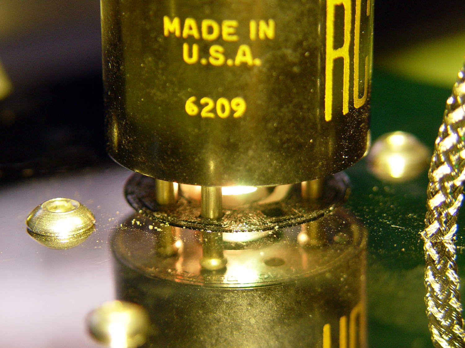
    0D3 Octal - 25 mm socket - raised LED
    0D3 Octal – 25 mm socket – raised LED

    After failing to plug in a different USB power supply, a close look at the USB connector showed the problem:

    Knockoff Arduino Nano - broken Mini-B connector
    Knockoff Arduino Nano – broken Mini-B connector

    A bit of needle-nose tweezering extracted the culprit from the power supply’s connector:

    Knockoff Arduino Nano - broken Mini-B connector - fragment
    Knockoff Arduino Nano – broken Mini-B connector – fragment

    I tried applying the world’s smallest dot of epoxy to the fracture, probably slobbered epoxy along the pins while reinserting it, and the Nano still doesn’t light up.

    Given that knockoff Nano boards cost a touch over two bucks delivered, it’s not clear transplanting a connector from one of the never-sufficiently-to-be-damned counterfeit FTDI USB adapters makes any sense.

  • Vacuum Tube LEDs: Mogul Bulb Side Light

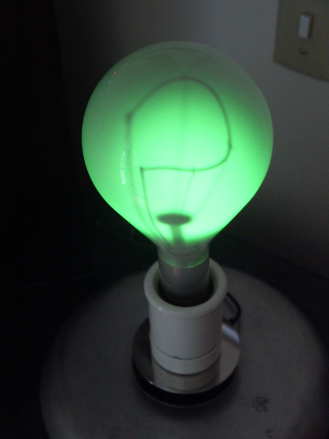
    The knockoff Neopixel on the 500 W mogul-base bulb failed in the usual way, so I rebuilt it with an SK6812 RGBW LED in a round cap:

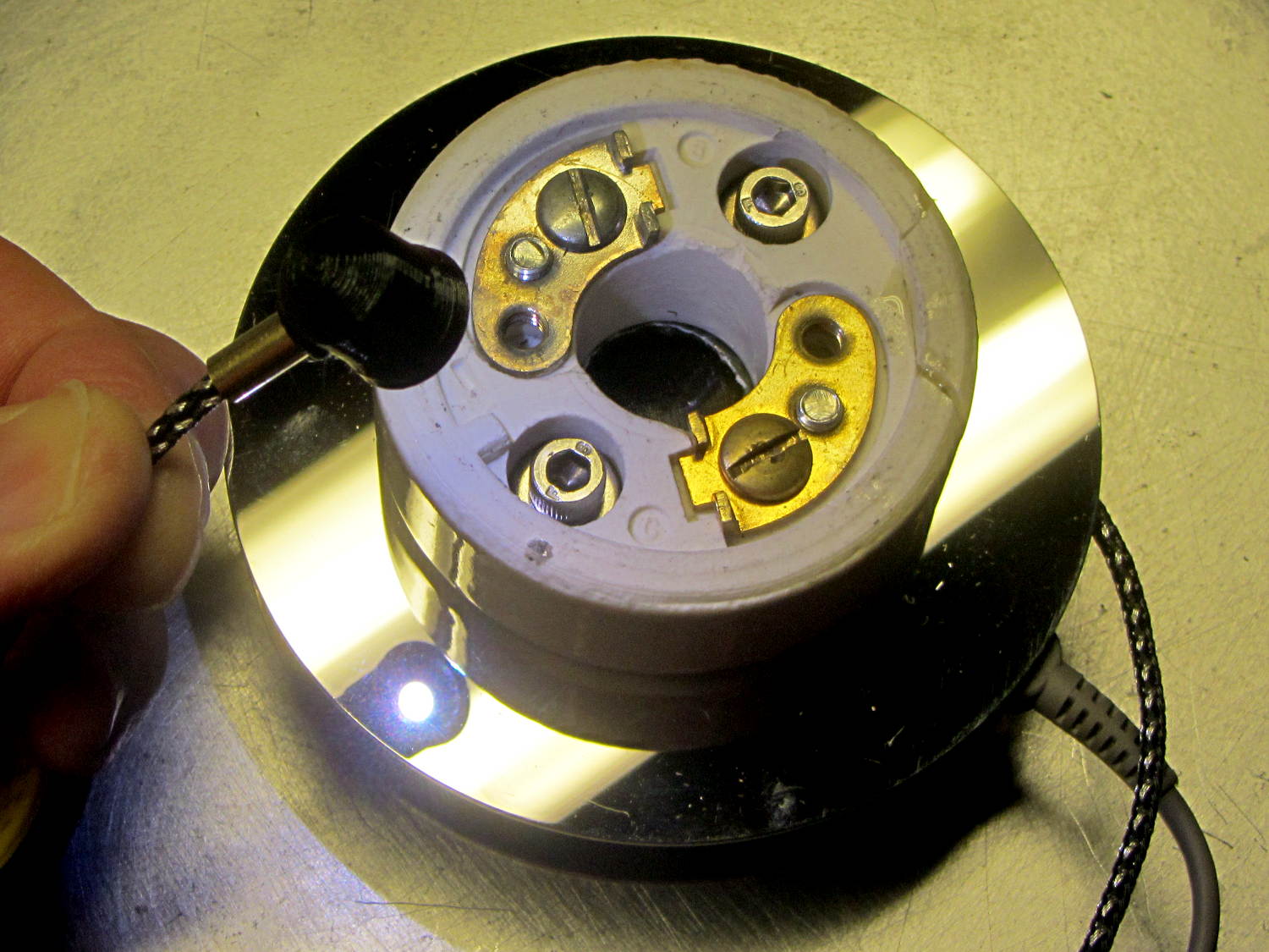
    Mogul lamp socket - SK6812 LED side cap
    Mogul lamp socket – SK6812 LED side cap

    The nice 1-¼ inch stainless socket-head cap screws replace the 1 inch pan-head screws that engaged maybe one thread due to the additional spacer between the USB port and the upper hard drive platter I added for good looks.

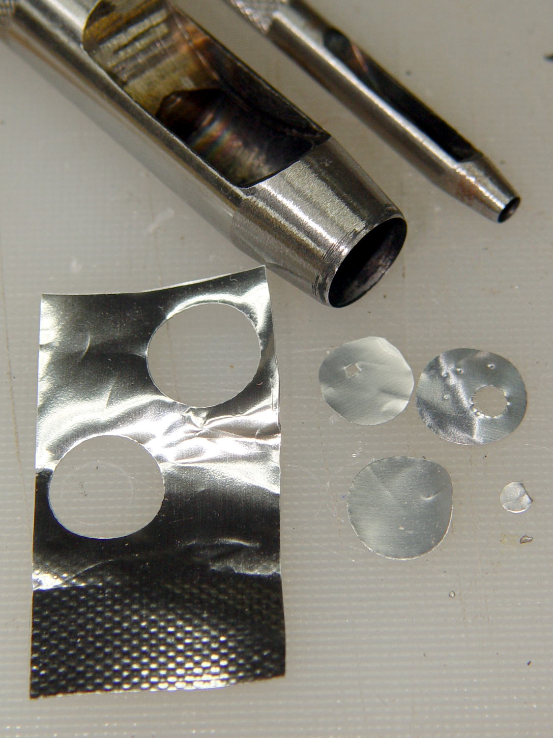
    I tried a few iterations of an aluminized Mylar (*) disk with various sized pinholes over the RGB trio to crisp up the filament shadow, because the SK6812 LED casts a more diffuse light than the W2812 LEDs:

    Aluminized Mylar pinholes for SK6812 RGBW LED
    Aluminized Mylar pinholes for SK6812 RGBW LED

    Even the ⅛ inch pinhole made the bulb too dim, so I settled for a fuzzy shadow:

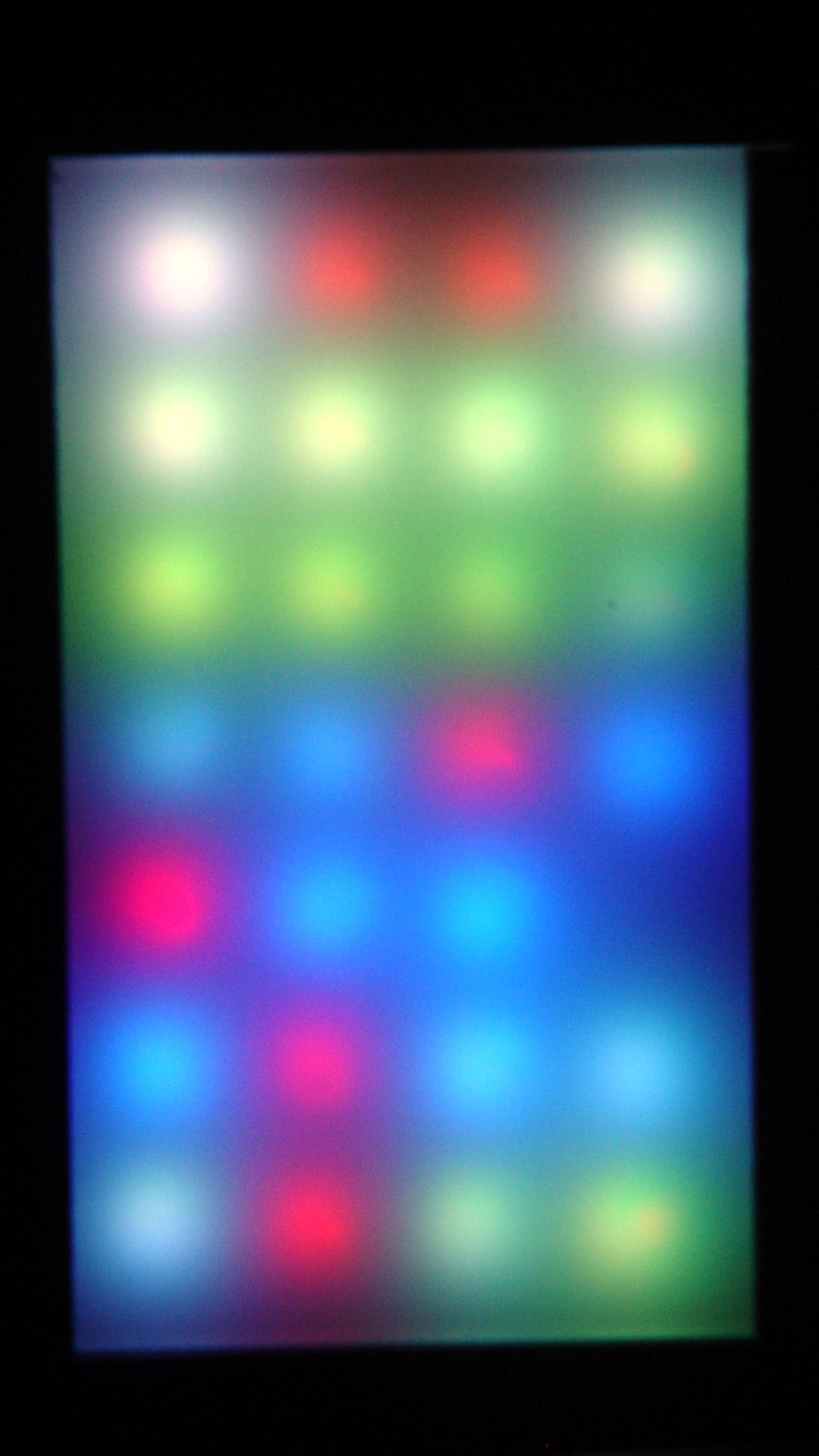
    500 W Mogul bulb - SK6812 RGBW LED - no pinhole - green phase
    500 W Mogul bulb – SK6812 RGBW LED – no pinhole – green phase

    The firmware has a tweak forcing the white LED to PWM=0, because this bulb looks better in saturated colors.

    (*) Here on earth, aluminized Mylar is nonconductive.

  • Byonics TinyTrak3+ vs. RFI

    Some weeks ago, the APRS + voice adapter on my radio began randomly resetting during our rides, sending out three successive data bursts: the TinyTrak power-on message, an ID string, and the current coordinates. Mary could hear all three packets quite clearly, which was not to be tolerated.

    I swapped radios + adapters so that she could ride in peace while I diagnosed the problem, which, of course, was both intermittent and generally occurred only while on the road. The TinyTrak doc mentions “… a sign of the TinyTrak3 resetting due to too much local RF energy”, so I clamped ferrite cores around All! The! Cables! and the problem Went Away.

    Removing one core each week eventually left the last core on the GPS receiver’s serial cable, which makes sense, as it plugs directly into the TT3. The core had an ID large enough for several turns (no fool, I), another week established a minimum of three turns kept the RFI down, so I settled for five:

    KG-UV3D APRS - ferrite on TT3 GPS cable
    KG-UV3D APRS – ferrite on TT3 GPS cable

    Prior to the RFI problem cropping up, nothing changed. Past experience has shown when I make such an assertion, it means I don’t yet know what changed. Something certainly has and not for the better.

    I swapped the radios + adapters and all seems quiet.

  • Cylindrical Cell Adapter: 18650 to 3xAAA

    Anker LC40 flashlights can use either one lithium 18650 cell or an adapter holding three AAA cells. I now prefer 18650 cells, but they’re nigh onto 4 mm smaller than the flashlight ID and rattle around something awful.

    I can fix that:

    Anker LC40 with 18650 cell adapter
    Anker LC40 with 18650 cell adapter

    Three new entries appear in the cell dimension table of my OpenSCAD inter-series battery adapter program:

    NAME = 0;
    ID = 0;       // for non-cell cylinders
    OD = 1;
    LENGTH = 2;
    
    Cells = [
      ["AAAA",8.3,42.5],
      ["AAA",10.5,44.5],
      ["AA",14.5,50.5],
      ["C",26.2,50],
      ["D",34.2,61.5],
      ["A23",10.3,28.5],
      ["CR123A",17.0,34.5],
      ["18650",18.8,65.2],
      ["3xAAA",21.2,56.0],
      ["AnkerLC40",23.0,55.0]           // Flashlight tube loose-fit for 3xAAA adapter
    ];
    

    I took the opportunity of adding OpenSCAD Customizer comments, which means this now works:

    OpenSCAD Customizer - dropdown selections
    OpenSCAD Customizer – dropdown selections

    The model looks about the same as before, although with a few more sides just for pretty:

    AnkerLC40 vs. 18650 Sleeve - Slic3r
    AnkerLC40 vs. 18650 Sleeve – Slic3r

    That was easy …

  • LF Crystal Tester: OLED Noise vs. Log Amp

    Having installed a cheap USB isolator to remove some obvious 60 Hz interference, the 100 Hz OLED refresh noise definitely stands out:

    Log amp - xtal amp - OLED noise
    Log amp – xtal amp – OLED noise

    The bottom trace comes from the 100× = 40 dB MAX4255 amplifier boosting the crystal output to a useful level. The fuzz on the waveform is actually the desired (off resonance) 60 kHz signal at maybe 30 mVpp, so the input is 300 µVpp.

    The worst part of the OLED noise looks like 100 mVpp, for about 1 mVpp at the crystal output, call it +10 dB over the desired signal. Some high-pass filtering would help, but it’s easier to just shut the display off while measuring the crystal.

    The top trace is the log amp output at (allegedly) 24 mV/dBV. The input bandwidth obviously extends way too low, as it’s neatly demodulating the input signal: the peaks correspond to both the positive and negative signal levels, so reducing the 1 µF input coupling caps will be in order.

    In between those 100 Hz groups, the input signal shines through to the log amp output at the V1 cursor. The peak noise rises 290 mV above that, so the log amp thinks it’s 12 dB higher. Pretty close to my guesstimated 10 dB, methinks.

    So, turning off the OLED should help a lot, which is feasible in this situation. If you must run the display while caring deeply about signal quality, you must devote considerably more attention to circuit construction quality.

  • Optiplex 980 Power Supply: Capacitor FAIL

    Came up from the Basement Laboratory to find my Dell Optiplex 980 PC had failed, with the power button and diagnostic 1 + 3 LEDs blinking amber. They built it back in June 2010, so section 3 of the Dell reference applies, the power supply status LED on the back panel was off, and, going straight to the heart of matter, I popped the top, disconnected the internal power supply cables, and poked the power supply test button:

    Optiplex 980 Power Supply - rear panel test button
    Optiplex 980 Power Supply – rear panel test button

    … and it’s dead.

    Inside, the system board sports a Mini-ATX power supply connector:

    Optiplex 980 - Mini-ATX power connector
    Optiplex 980 – Mini-ATX power connector

    I originally hoped to swap a supply from an Optiplex 755 (also in a Small Form Factor case) residing on the recycle heap, but it has an ordinary ATX connector:

    Optiplex 755 - ATX power connector
    Optiplex 755 – ATX power connector

    So I moved the 980’s SSD and dual-Displayport video card into the 755, fired that devil up, and … it worked!

    With my desktop back in action, albeit somewhat slower, I popped the dead supply’s case by violating the Warranty Void If This Label Removed sticker to unscrew the last screw:

    Optiplex 980 Power Supply - overview
    Optiplex 980 Power Supply – overview

    Notice anything?

    The electrolytic capacitors over on the left look like this:

    Optiplex 980 - Good capacitor
    Optiplex 980 – Good capacitor

    The cluster of caps on the upper right have bulged pressure-relief lids, like this:

    Optiplex 980 - Bulging capacitor 1
    Optiplex 980 – Bulging capacitor 1

    And this:

    Optiplex 980 - Bulging capacitor 2
    Optiplex 980 – Bulging capacitor 2

    And this:

    Optiplex 980 - Bulging capacitor 3
    Optiplex 980 – Bulging capacitor 3

    None had ruptured, but they’re obviously feeling a bit nauseous.

    Given the 980’s mid-2010 manufacturing date, this probably isn’t capacitor plague, just simple overheating from operating in a dead-air zone amid all those heatsinks and wires. Some of the Usual Unnamed Sources suggest overheating the capacitors is how manufacturers ensure their hardware doesn’t last forever, without being obvious about planned obsolescence; I’m loathe to ascribe to malice what can be explained by design desperation.

    A Genuine Dell replacement supply from eBay ($25 delivered) came from yet another “small form factor” Dell chassis, so it isn’t quite the same size, lacks a supply test button / LED status light, and doesn’t quite fit:

    Optiplex 980 - replacement supply misfit
    Optiplex 980 – replacement supply misfit

    Nothing a sheet metal nibbling tool can’t fix, though, given I haven’t developed a deep emotional attachment to the chassis. I gnawed off the left side of the frame and squared up the rim around the lower screw, after which the opening fit the supply pretty well, although the latching tab bent up from the bottom of the chassis didn’t quite engage the far end of the supply. No big deal: it’s not in a high-vibration environment.

    The new-to-me supply also carries an ATX connector, but the eBay seller included a Mini-ATX adapter. Jamming the adapter + wires into the space available required concerted muttering, assisted by tucking the SSD under the DVD-RW drive. No pictures, as it’s a classic seven pounds in a five pound box situation.

    And then It Just Worked again.

  • AT26 / TF26 Quartz Resonator Identification

    There’s not much room on an AT26 / TF26 can for a readable label, unless one owns a metal-marking laser, but a simple bar code should let me identify each one:

    Quartz Resonators - binary marking
    Quartz Resonators – binary marking

    The empty “0” slot down at the bottom will hold the crash-test dummy resonator I’ve been using to get the tester working.

    The red-and-blue stripes from plain old fine-point Sharpie pens will rub off under duress, which I hope to avoid. After finishing up, I’m still not sure blue makes a better zero than red; you can make a convincing argument either way:

    Binary marked AT26 Quartz Resonators
    Binary marked AT26 Quartz Resonators

    The bag allegedly contained 25 resonators, although I’m willing to agree the last one escaped into the clutter on or under the Electronics Workbench.