The Smell of Molten Projects in the Morning

Ed Nisley's Blog: Shop notes, electronics, firmware, machinery, 3D printing, laser cuttery, and curiosities. Contents: 100% human thinking, 0% AI slop.

Category: Amateur Radio

Using and building radio gadgetry

  • Baofeng UV-5: Squelch Pop Suppression

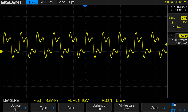
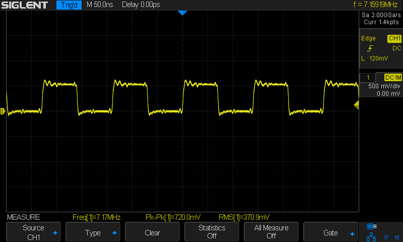
    Our first ride with the Baofeng UV-5 radios subjected us to loud pops around each transmission. Back on the bench, this is the signal applied to the earbud during a no-audio simplex kerchunk:

    Baofeng - squelch pops
    Baofeng – squelch pops

    The small noise burst to the right of the center, just before the downward pulse, happens after the carrier drops and before the squelch closes; it’s familiar to all HT users.

    The huge pulses, upward at the start and downward at the end, cause the pops. They’re nearly 3 V tall, compared with the 300-ish mV squelch noise, and absolutely deafening through an earbud jammed in my ear. Mary refused to listen, so we finished the first ride in companionable silence.

    I think the radio switches the audio amp power supply on and off to reduce battery drain. It’s obviously a single-supply design, so we’re looking at a hefty DC blocking capacitor charging and discharging through the earbud resistance. I suppose that’s to be expected in a $25 radio.

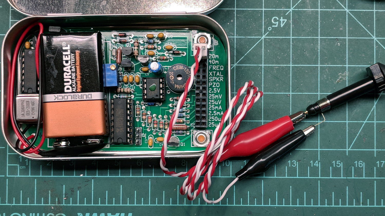
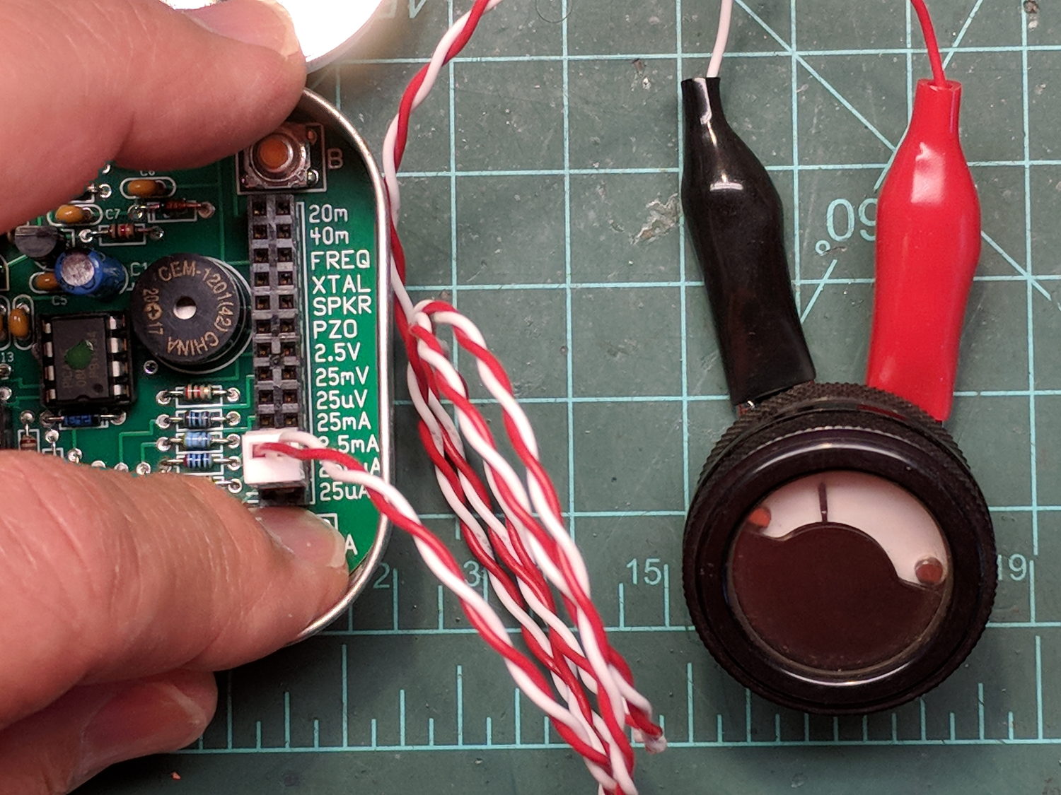
    The obvious solution: clamp the audio signal to something reasonable, perhaps with a pair of nose-to-tail Schottky diodes across the earbud. Rather than using axial diodes, along the lines of the 1N5819 diodes in the WWVB preamp, I used a BAT54S dual SMD diode as a tiny clamp:

    BAT54S dual-Shottky diode - SMD package
    BAT54S dual-Shottky diode – SMD package

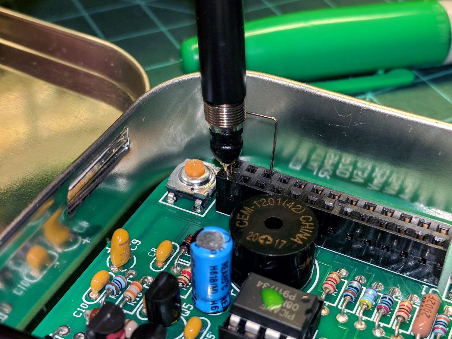
    No pix of the final result, but it’s basically two wires soldered alongside the SMD package, surrounded by a snippet of heatstink tubing to stabilize the wires and protect the SMD leads. It might actually survive for a while, even without the obligatory epoxy blob.

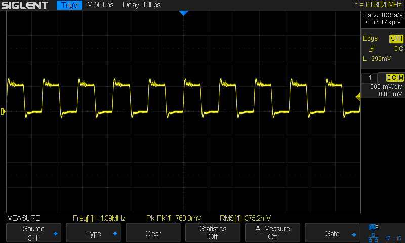
    The BAT54S clamps the pops to 200-ish mV, as you’d expect:

    Baofeng - squelch pops - clamped - 500mV-div
    Baofeng – squelch pops – clamped – 500mV-div

    That’s a kerchunk at twice the vertical scale. The very thin spike at the start of each pop isn’t audible, as nearly as we can tell, and I’ve cranked up the audio gain to make the squelch noise more prominent. Your ears will determine your knob setting.

    With the audio amp applying 3 V to the diodes at the start of each pop, you’re looking at an absurdly high pulse current. I’m sure the radio exceeds the BAT54 datasheet’s 600 mA surge current limit by a considerable margin, but I’m hoping the short duration compensates for some serious silicon abuse.

    Tamping those pops down made the radios listenable.

    I’ve often observed that Baofeng radios are the worst HTs you’d be willing to use.

  • Baofeng UV-5 to Bike Helmet Wiring

    Rather than 3D print and hand-wire a plug adapter to fit the socket around the Baofeng UV-5 mic and speaker jacks, I cheated:

    Baofeng headset - harvested plug
    Baofeng headset – harvested plug

    Un-wearably bad Baofeng headsets now cost just over a buck apiece in lots of five, delivered halfway around the planet, and provide:

    • A compatible molded mic+speaker plug
    • A decent length of four-conductor cable with solder-meltable insulation
    • An unlistenably bad earbud on a stick
    • A lump with an electret mic and PTT switch
    • Various junk I’ll never use

    The “hook earpiece” seems to have been designed by someone who had read the specs for a human head, but had never actually met a human being.

    The wire colors from the dual plug, along with the wire colors for the repurposed USB cable to the headset, and the PTT connection:

    Baofeng headset cable vs helmet cable - wire colors
    Baofeng headset cable vs helmet cable – wire colors

    Then wire it up accordingly:

    Baofeng headset wire plate - first wiring
    Baofeng headset wire plate – first wiring

    The small heatstink tubing surrounding each connection isn’t easily visible, which, in the case of the ground / common lump, is a Good Thing. I chivied a strip of Kapton under the whole mess, folded it over on top, squished it together, then secured it with 1/4 inch tape extending over the plate edges. The cable ties stick out far enough to keep the joints from rubbing on anything; it’s not built to last for a thousand years, but should let us hear how this lashup works.

    Now, to the bikes:

    Baofeng headset wire plate - in use
    Baofeng headset wire plate – in use

    I’m convincing myself a little supporting ring under the SMA-to-UHF adapter won’t actually stabilize the precarious-looking joint.

  • Baofeng UV-5 Headset Wiring Plate

    My venerable amateur radio HT APRS-voice interfaces have recently begun failing and, given poor APRS coverage in Poughkeepsie due to having two iGates shut down (due to the aging radio geek population), I decided it’s time to simplify the radio interface. Given that HTs are designed to run with an external electret mic and earbud, the “interface” becomes basically some wires between the radio’s jacks, a repurposed USB plug on the bike helmet, and the PTT switch on the handlebar.

    I expected to add a resistive attenuator to the earbud, but it wasn’t clear whether the mic would need an amplifier similar to the one in the APRS interface, so I decided to start as simply as possible.

    The general idea is to anchor all the cables to a plate on the back of the radio, interconnect as needed, then “protect” everything with tape. The pocket clip has M2.5 screws on 26 mm (not 25.4, honest) centers, so that’s how it started:

    Baofeng headset wire plate - dimensions
    Baofeng headset wire plate – dimensions

    The four holes beside the tabs will serve as starting points for rectangular notches holding cable ties lashing the wires to the plate:

    Baofeng headset wire plate - drilled
    Baofeng headset wire plate – drilled

    Like this:

    Baofeng headset wire plate - sawed
    Baofeng headset wire plate – sawed

    That’s hot and nasty, straight from the bandsaw.

    After some edge cleanup, add obligatory Kapton tape to insulate stray wires from the aluminum:

    Baofeng headset wire plate - installed
    Baofeng headset wire plate – installed

    The alert reader will note beveled corners on one plate and square corners on the other; think “continuous product improvement”.

    The big rectangular gap in the middle of the plate provides (barely enough) finger clearance to push the battery release latch.

    Now, to wire it up …

    The dimensions of the recess surrounding the jacks on the Baofeng UV-5, just to have them around:

    Baofeng headset jack socket - dimension doodle
    Baofeng headset jack socket – dimension doodle

    Which came from measurements of both the Wouxun and Baofeng radios:

    Baofeng Wouxun headset jack sockets - measurements
    Baofeng Wouxun headset jack sockets – measurements
  • Squidwrench Electronics Workshop: Session 3

    Ex post facto notes from the third Squidwrench Electronics Workshop.

    Exhibit various 50 Ω resistors, including my all-time favorite, a 600 W 3 GHz dummy load:

    600 W Dummy Load Resistor
    600 W Dummy Load Resistor

    … down to a 1/8 Ω metal film resistor.

    The dummy load’s N connector triggered a regrettable digression into RF, belatedly squelched because I wasn’t prepared to extemporize on AC concepts like reactance which we haven’t covered yet.

    Discussion of resistor applications, power handling, power derating with temperature, etc:

    Whiteboard - Session 3 - Resistor power derating
    Whiteboard – Session 3 – Resistor power derating

    Why you generally won’t find 50 Ω load resistors in Raspberry Pi circuits. Cartridge heaters for 3D printers, not aluminum power resistors, although everyone agrees they look great:

    Power resistors on heat spreader
    Power resistors on heat spreader

    Discussion of voltage vs. current sources, why voltage sources want low internal resistances and current sources want high resistances. Bungled discussion of current sources by putting diodes in parallel; they should go in series to show how added voltage doesn’t change current (much!) in sources driven from higher voltages through higher resistances:

    Whiteboard - Session 3 - Voltage vs Current Sources
    Whiteboard – Session 3 – Voltage vs Current Sources

    Use Siglent SDM3045X DMM in diode test mode to measure forward drop of power / signal / colored LEDs, discuss voltage variation with color / photon energy. Measure 1.000 mA test current for all forward voltages.

    Compute series resistor (500 Ω) to convert adjustable power supply (the digital tattoo box, a lesson in itself) into reasonable current source; roughly 10 V → 20 mA. Find suitable resistor (560 Ω) in SqWr junk box parts assortment, digression into color band reading.

    Wire circuit with meters to measure diode current (series!) and voltage (parallel!), measure same hulking power diode (after discovering insulating washers now in full effect) as before in 1 mA steps to 10 mA, then 15 and 20 mA, tabulate & plot results:

    Whiteboard - Session 3 - Diode current vs forward drop
    Whiteboard – Session 3 – Diode current vs forward drop

    Discover warm resistor, compute power at 20 mA, introduce cautionary tales.

    Lesson learned about never returning parts to inventory, with 560 Ω resistor appearing in diode drawer. Cautionary tales about having benchtop can of used parts as front-end cache for inventory backing store.

    Another intense day of bench work!

  • QRPme Pocket Pal II: RF Waveforms and Meter Test

    The QRPme Pocket Pal II produces RF test signals in the 20 meter and 40 meter bands, both square-ish waves derived from its 14.31818 MHz oscillator-in-a-can:

    QRPme 20 meter - clip leads
    QRPme 20 meter – clip leads

    That’s the 20 meter signal, seen through the twisted pair test lead with alligator clips clamped on the scope probe, thusly:

    QRPme Pocket Pal II - clip leads to probe tip
    QRPme Pocket Pal II – clip leads to probe tip

    When you’re working with RF signals, the “ground” part of the probe circuit matters:

    QRPme 20 meter - probe tip gnd
    QRPme 20 meter – probe tip gnd

    That’s with the probe and its short spring ground jammed directly into the header:

    QRPme Pocket Pal II - probe tip gnd
    QRPme Pocket Pal II – probe tip gnd

    Well, in this case, signal quality doesn’t matter very much, as you’re using the Pocket Pal II at a hamfest (or your bench) to determine if an HF radio is completely dead.

    Here’s the 40 meter output, with the J3 jumper in place and the probe jammed into the header:

    QRPme 40 meter - J3 on - probe tip gnd
    QRPme 40 meter – J3 on – probe tip gnd

    Pulling the J3 jumper off doubles the test signal amplitude:

    QRPme 40 meter - J3 off - probe tip gnd
    QRPme 40 meter – J3 off – probe tip gnd

    Nothing wrong with those signals! In a pinch, those edges probably produce harmonics up in the UHF bands.

    For completeness, here’s the 250 μA DC output driving a contestant chosen from the Box o’ Meters:

    QRPme Pocket Pal II - 250 uA meter test
    QRPme Pocket Pal II – 250 uA meter test

    Eyeballometrically, the meter wants to see 1 mA for full-scale deflection, which is the whole point of the tester.

    Recommended, with some early notes.

  • QRPme Pocket Pal II

    A QRPme Pocket Pal II could be a suitable project for a Squidwrench “advanced soldering” class:

    QRPme Pocket Pal II - front
    QRPme Pocket Pal II – front

    Yes, it comes with a tin case:

    QRPme Pocket Pal II - tin case
    QRPme Pocket Pal II – tin case

    You must fit your own insulating sheet under the PCB; polypropylene snipped from a retail package works fine.

    It’s intended as a “mint tin sized tester for all kinds of hamfest goodies”, but it seems like a nice source of small currents, voltages, and signals suitable for stimulating all manner of circuitry one might encounter in later sessions of a beginning electronics class.

    Before using it, of course, one must solder a handful of small through-hole parts into the PCB, a skill none of us were born with.

    For completeness, the back side, hot from the soldering iron:

    QRPme Pocket Pal II - rear
    QRPme Pocket Pal II – rear

    The kits (always buy two of anything like this) arrived minus a few parts, which I suspect was due to an avalanche of orders brought on by a favorable QST review. Fortunately, I (still) have a sufficient Heap o’ Parts to finish it off without resupply, although a hank of 9 V battery snaps will arrive in short order.

  • RF Controlled Area Warning

    Spotted this at the top of a motel stairwell:

    RF Controlled Area - roof access warning
    RF Controlled Area – roof access warning

    More detail:

    RF Controlled Area - detail
    RF Controlled Area – detail

    The antennas face away from the hatch, so it’s not as if the RF would shear you off as you climbed through:

    Hampton Inn - RF Controlled Area - cell sector antennas
    Hampton Inn – RF Controlled Area – cell sector antennas

    I wonder if the hatch atop Vassar Main sports a similar warning …