Ed Nisley's Blog: Shop notes, electronics, firmware, machinery, 3D printing, laser cuttery, and curiosities. Contents: 100% human thinking, 0% AI slop.
Having just deployed a trail camera to see what might be skulking about in the middle of the night, this appeared just before the (not fresh) batteries died:
The Early Opossum
It’s hard to tell with possums, but I’d say that critter is on a mission!
I’m still figuring out proper distances; the possum is about two feet away, which is obviously much too close. Great focus on the water barrels standing by the garage, though.
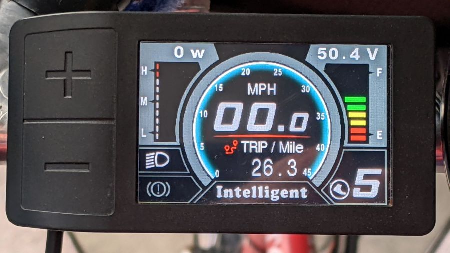
I got the Bafang DPC-18 display for my Tour Easy specifically to put the control buttons on the handgrip, rather than the buttons on the left of the 500C display on Mary’s bike:
Tour Easy Bafang – display 26 mi
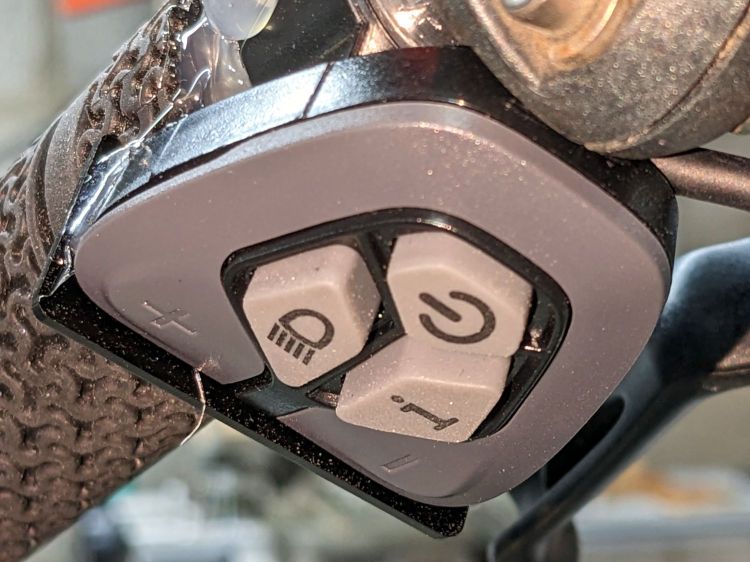
The first pass put them on the left handgrip, just behind the thumb throttle:
Bafang DPC-18 control buttons – initial mount
This turned out to be a catastrophically bad position, because the “buttons” extend all the way to the edge of the mount and trigger when pressed a fraction of a millimeter: the dark line visible under the light gray top is the entire range of motion.
My resting hand position on the grip put the edge of my gloved index finger along the buttons, where it would inexorably nudge the + button until I was riding in assist level 9 (Rocket Sled) mode.
One ride was enough to convince me those buttons needed a Mollyguard:
It is, of course, a laser-cut piece of 1.5 mil black acrylic, held in place with hot-melt glue. Because the button housing isn’t mounted symmetrically on the handlebar, I cut a few paper templates before getting the position and size right.
A view from the front shows the lip sticking up over the buttons:
Bafang DPC-18 button Mollyguard – front view
FWIW, the asymmetric mount put the buttons on the rider’s side of the flat handlebars found on contemporary upright city-rider style bikes. It makes perfect sense in that context, but didn’t help me in the least.
With the Mollyguard in place, I rotated the whole button assembly around the handgrip to allow pushing the buttons with my thumb in its natural position.
Now the assist level changes only when I want it to!
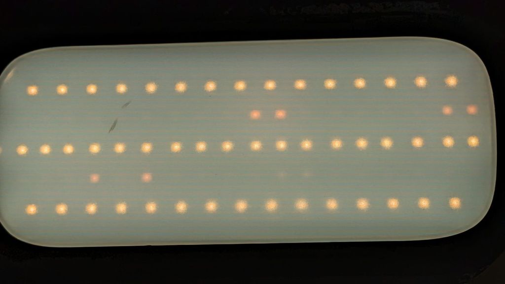
The next morning the dead section lit up again, albeit with a dim ring at its right end. I think one LED in that string failed open and darkened the whole string, then failed short under the voltage stress, and is now quietly simmering in there with slightly higher than usual current.
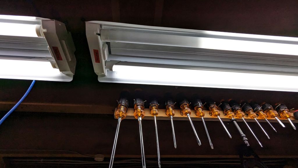
The lights over the workbench weren’t in the first wave of conversions, so they may be only four years old.
For sure, they have yet to approach their 50000 hour lifetime …
Confirming the diagnosis, the cool white LEDs worked fine with the light turned on:
Miroco floor lamp – all-LED mode fail
With nine spare SI2306 transistors in hand from the last time in this rodeo and minus the sticky adhesive foam covering the PCB, replacing the other driver transistor was no big deal, whereupon the lamp once again worked the way it should:
Miroco floor lamp – restored warm LEDs
While I was in there, I spotted a dent in the input filter cap:
Miroco floor lamp – OEM capacitor
Most likely I squished a wire between the cap and the U-shaped steel strut joining the two halves of the pole. I relocated the replacement cap off the circuit board into an open space with a bit more room:
Miroco floor lamp – recapped
The fragile wires running to the lamp head got their own sheet of silicone tape (not shown here) to isolate them from the U-strut:
Miroco floor lamp – LED wiring
Tuck all the wires back inside, snap the housing together, and it should be good for another uhh half year or two.
It’s hard to be sure about such things, but I now have eight spare transistors …
The “live hinge” on my overnight eyeglass case shattered when it hit the floor (these things happen), which prompted me to finish a longstanding project of replacing the inadequate / worn out padding in my most-used cases to reduce rattles while in my pocket.
I’d long ago cut craft foam sheets to fit some of the cases, so I started by scanning a sample:
Zenni case pad
Admittedly, black foam on a white background isn’t much to look at, but it did fit one of the cases pretty well.
Rotate the image to make things simple, convert it into a monochrome bitmask, import it into LightBurn, fair some Bezier curves around it, duplicate and tweak for the other not-quite half of the case:
Zenni eyeglass case pads – LB Layout
I ended up with several different versions for various cases, but you get the general idea:
Zenni eyeglass case pads – installed
They’re all cut from 2 mm EVAfoam sheets which, despite the “vinyl” in their name, do not contain chlorine and are suitable for laser cuttery.
Some of the deeper case halves required strips of adhesive sheet to secure the foam, but most sheets dry-fit in place.
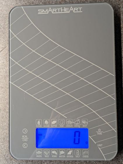
The four control “buttons” on the SmartHeart kitchen scale are copper-foil tabs that sense the presence of your finger though about 5 mm of white plastic and glass:
SmartHeart 19-106 Kitchen Scale – top view
The main failure mode seemed to come from the microcontroller locking up and refusing to recognize any of the buttons, most annoyingly the On/Tare button, while continuing to measure whatever weight was on the scale with whatever zero point it chose. Recovery involved waiting until the thing timed out and shut itself off.
The two buttons on the left select Kilocalories for any of the various foods arrayed around the display. Depending on how it jammed during startup, it might display the Kilocalorie value for, say, sugar, while ignoring all button presses. As the manual does not mention any way to return to weights after activating the Kilocalorie function, other than turning it off, it’s not clear recognizing the other buttons would be much help.
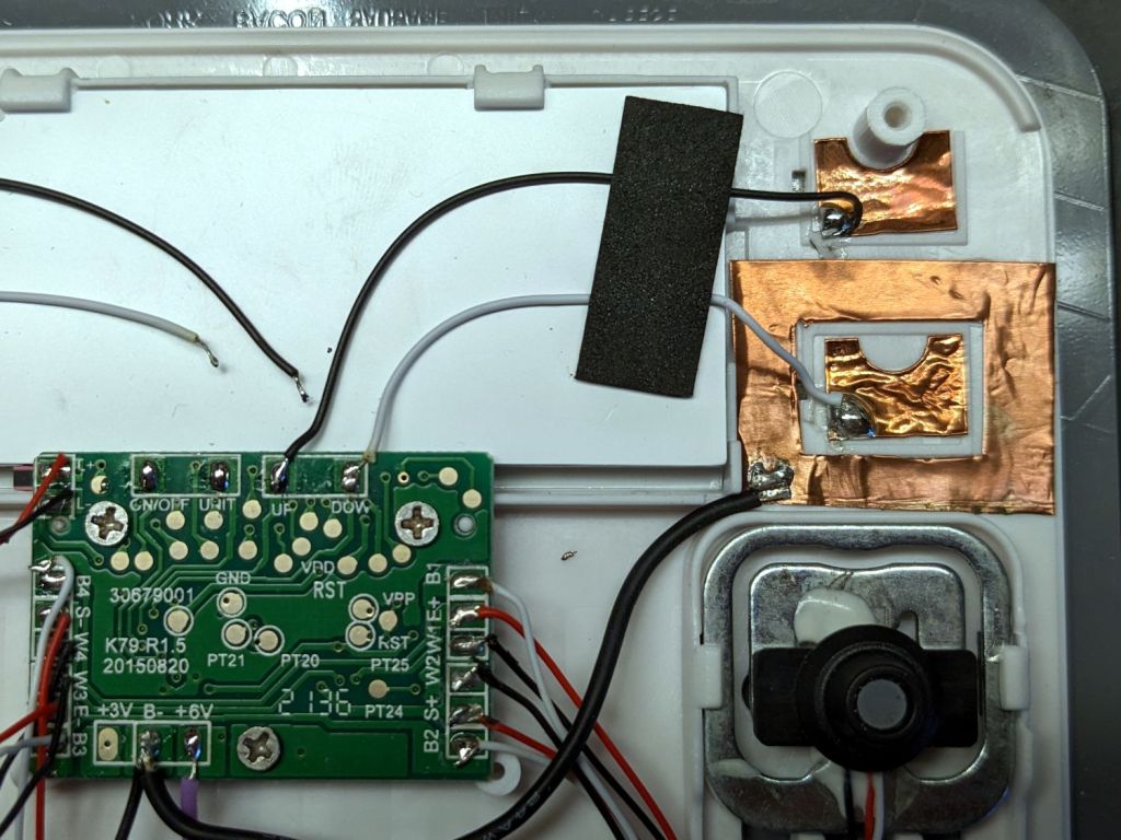
Because we have no use for those functions, I unsoldered the wires to those sensor pads and it no longer jams in that mode:
SmartHeart 19-106 Kitchen Scale – PCB detail
The alert reader will note the PCB legend says I have unsoldered the ON/OFF and UNIT wires. If one believes the silkscreen, the PCB dates back to 2015, so it now carries a reprogrammed microcontroller with functions that no longer match the silkscreen.
The overall soldering quality resembles mine on a bad day.
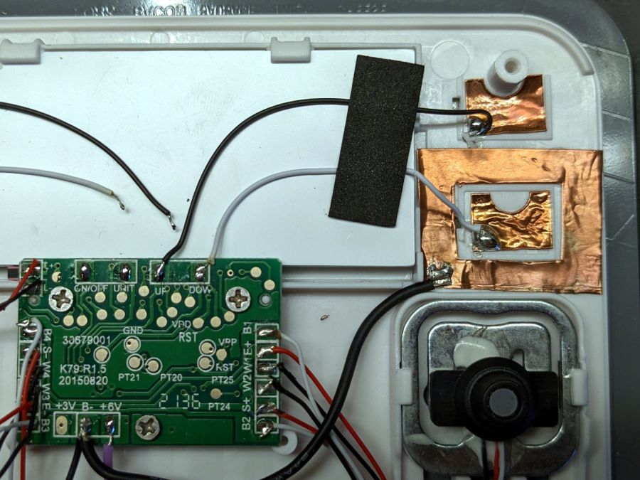
With those out of the way, the scale still jammed and refused to recognize the remaining two buttons. I wondered if it was somehow sensing ghost fingers over both sensors and waiting for one to vanish, so I added a shield ring around the power tab:
SmartHeart 19-106 Kitchen Scale – shielded sensor
That reduced the sensitivity of both sensors to the point where they pretty much didn’t work, without reducing the number of jams.
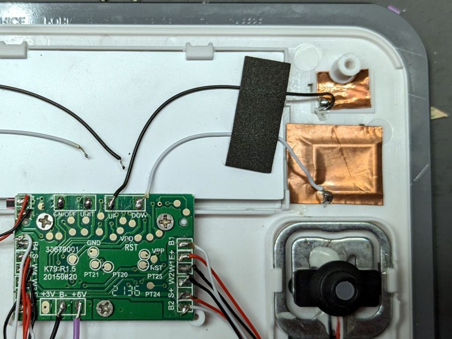
So I tried increasing the sensitivity of the power tab by replacing it with a larger copper foil sheet:
SmartHeart 19-106 Kitchen Scale – larger sensor
That definitely got its attention, as it will now respond to a finger hovering half an inch over the glass, as well as a finger on the bottom of the case: it can now turn on and jam while I pick it up.
More tinkering is in order, but it’s at least less awful in its current state than it was originally, so I can fix a few other things of higher priority.