Ed Nisley's Blog: Shop notes, electronics, firmware, machinery, 3D printing, laser cuttery, and curiosities. Contents: 100% human thinking, 0% AI slop.
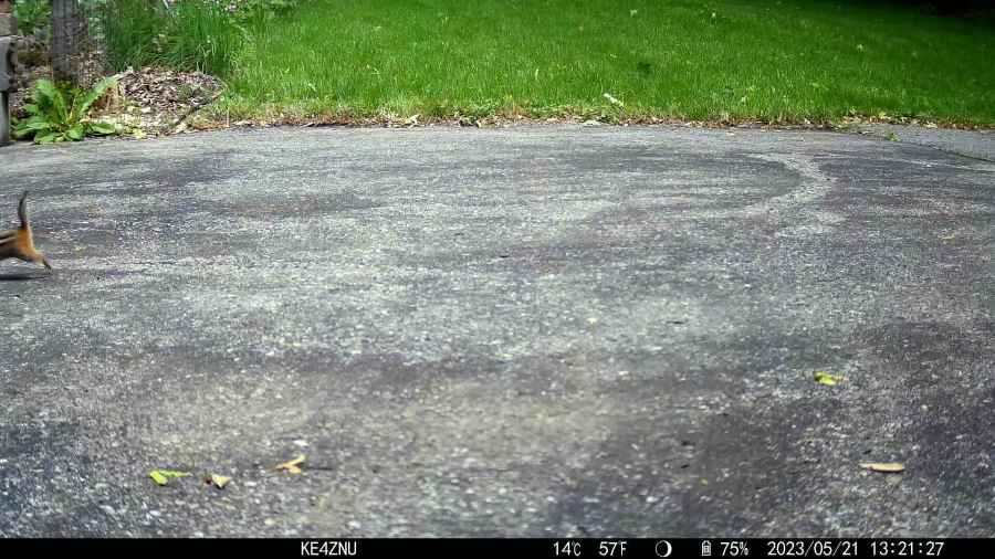
An unfortunate confluence of weather, schedule, and enthusiasm led to mowing all the yard in one session:
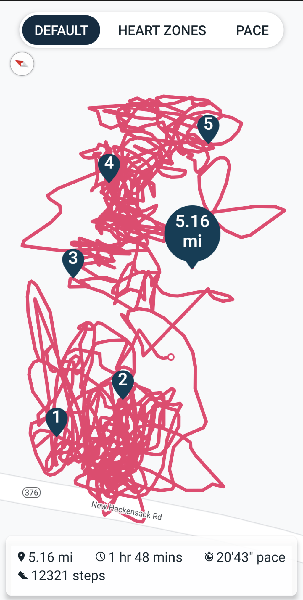
Mowing pattern – 2023-05-27
I managed to remember to pause the tracker during a break in the middle, so it’s really just shy of three wall-clock hours from start to finish. It’s amazing how much work you (well, I) can get out of 100 mg of caffeine.
Despite what you see here, the path on what’s euphemistically called “our lawn” show a much more organized solution to the problem of covering our property with non-overlapping foot-and-a-half stripes. As with my leaf-shredding track, I neither venture into the road nor mow the neighboring yards.
That’s built directly from the original specs to get the spacing and symmetries correct. The freebies I could find all suffered from various degrees of bad design & layout.
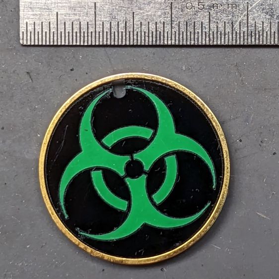
Shrunken down to 25 mm OD, the tips become vanishingly small:
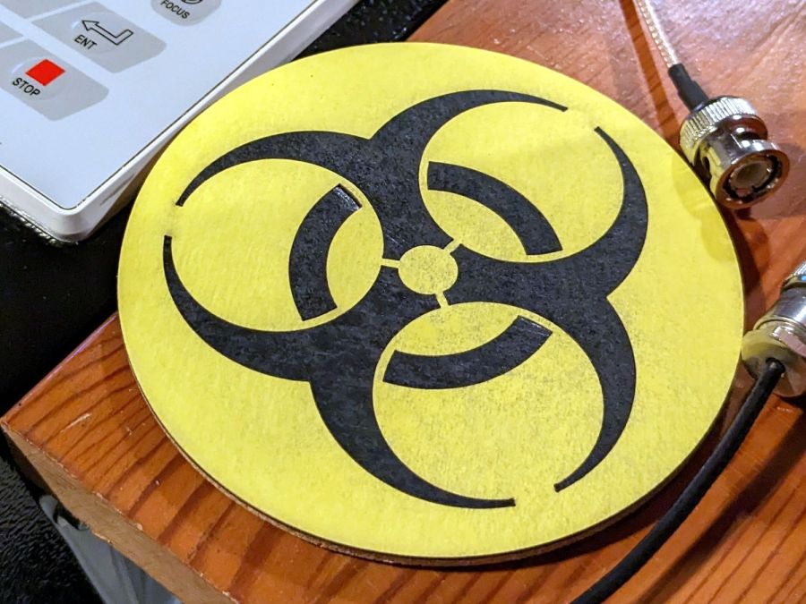
Biohazard earring – vinyl sample
It’s the same laser-safe polyurethane vinyl as the SD card reader, this time applied to 3 mm black acrylic. The “gold” ring is just parked in place, as this one wasn’t presentation-quality.
Contrary to the usual transfer-tape method of applying PSA vinyl, I stuck the sheet to the acrylic before cutting, then weeded it directly off the acrylic:
Biohazard earring – vinyl weeding
Kiss-cutting the vinyl with dot mode ate into the acrylic, but the soon-to-be-weeded areas protected the surroundings and the result came out looking pretty good. To me, anyhow.
Flushed with success, I tried some almost certainly not laser safe glow-in-the-dark tape:
Biohazard earring – GITD weeding fail
The mess in the upper left is the tape’s double-sided adhesive intended to hold the glowy layer in place forever. Of course it weeded poorly!
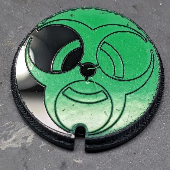
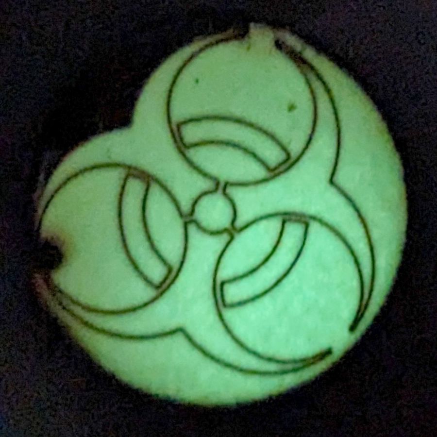
Seen in its natural environment, however, weeding may not be necessary:
Biohazard earring – GITD tape glow
Engraving the rebated rim leaves quite a bit of debris & scorch marks around the perimeter. A mask layer atop the GITD tape seems like a Good Idea™.
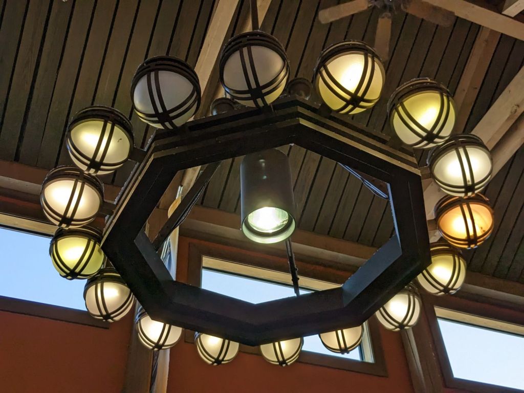
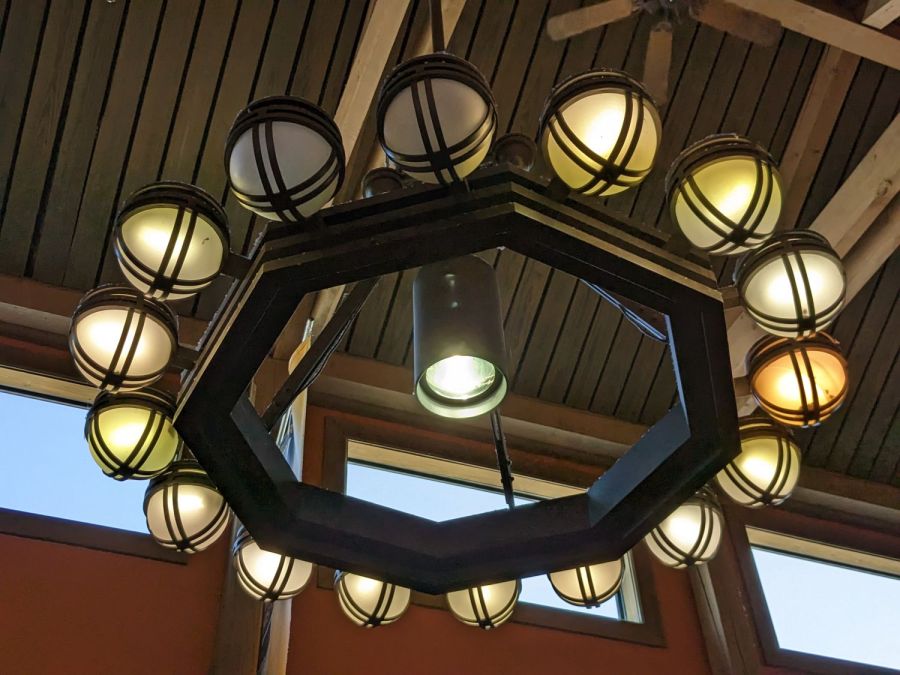
Spotted in a soon-to-be-rebuilt rest area on I-87 north of Kingston NY, a chandelier stuffed with old-school CFL bulbs of various vintages:
NYS I-87 Rest Area – CFL chandelier
The yellowish dome on the far right might still house an incandescent bulb, but I can’t tell from here.
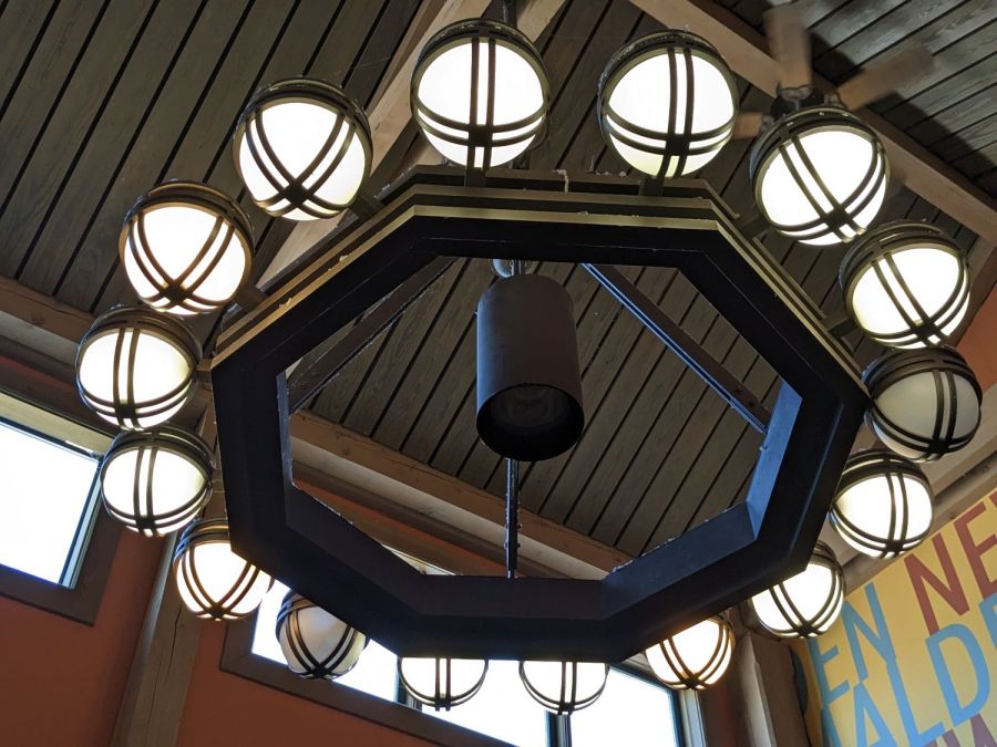
Judging from the high color temperature and even illumination, the chandelier next to it has 16 newish LED bulbs:
NYS I-87 Rest Area – LED chandelier
What’s of interest: both chandeliers have two dead bulbs and, perhaps, the center floodlight of the LED fixture had died, too. We don’t know how long they’ve been in place, other than that the LEDs are certainly more recent, but a 6% failure rate is nothing to brag about.
From what I’ve seen, the reliability of both CFL and LED bulbs is greatly overstated and certainly do not justify preemptive replacement of a working bulb of any vintage.
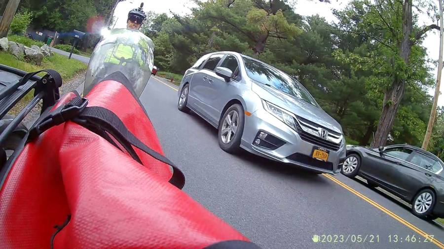
As expected, the internal battery does not last for our usual hour-long rides, so the cameras now operate in “car mode”: recording starts when we plug in the USB battery pack and stops shortly after unplugging.
I started with the waterproof case on my bike:
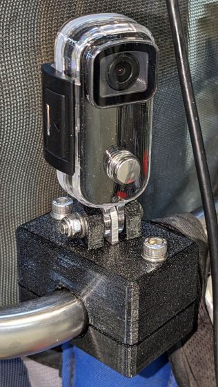
Tour Easy – SJCAM C100 mount – installed
Which (obviously) does not allow for an external battery, so they’re now in the “frame” mount. The hatch covering the MicroSD card and USB Micro-B connector (and a Reset button!) is on the bottom of the camera, but (fortunately) the whole affair mounts up-side-down and the settings include an image flip mode.
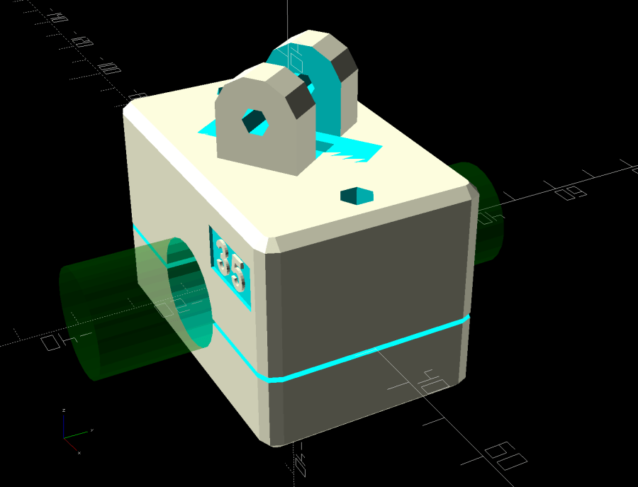
The ergonomics / user interface of this whole setup is terrible:
The camera’s flexible hatch is recessed inside the frame far enough that it cannot be opened without using a small & sharp screwdriver
The USB jack is slightly off-center, so lining the plug up with the camera body doesn’t align it with the jack
The MicroSD card is in a push-to-release socket, but its raised ridge faces the hatch flap and cannot be reached by a fingernail. I added a small tab that helps, but it’s difficult to grasp.
Extracting the video files from the camera through the app is an exercise in frustration. Having already figured out how to do this for the other cameras in the fleet, it’s easier to fumble with the MicroSD card.
I devoutly hope we never really need any of the videos.
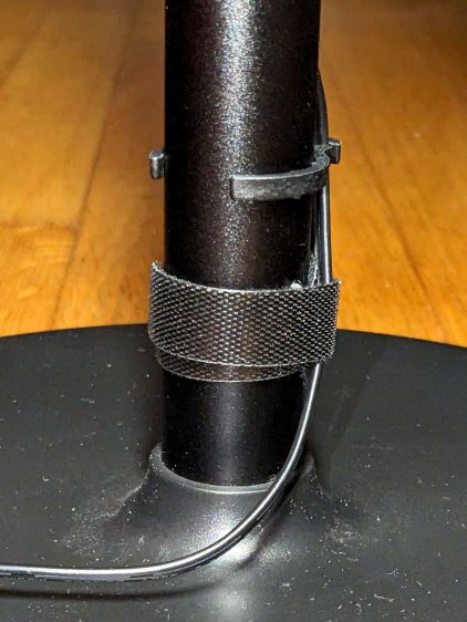
Because the lamp has a big nut apparently holding the pole socket to the base, I figured a dab of threadlock on the pole or the base would solve the problem: lock the pole to the socket, then remove the nut to disassemble when needed. That turned out to be a Bad Idea™.
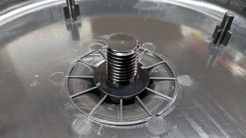
The socket is a plastic part separate from the base cover plate:
Miroco floor lamp base – socket
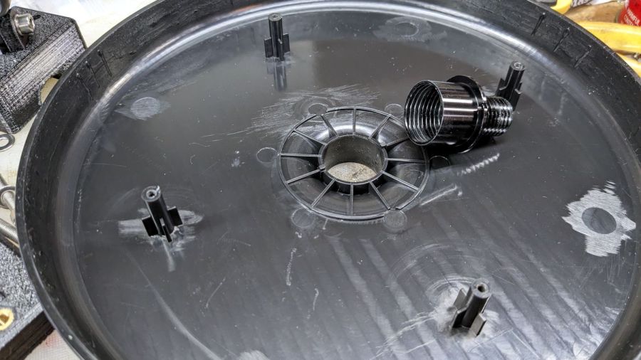
A pair of keys prevent the socket from rotating in the hole:
Miroco floor lamp base – socket in place
Four threaded bosses (two visible there) hold the rim of the cover to the weight, with the socket doing the hard work.
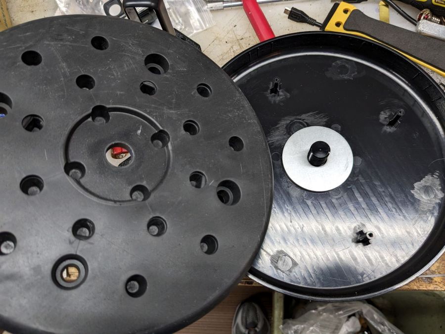
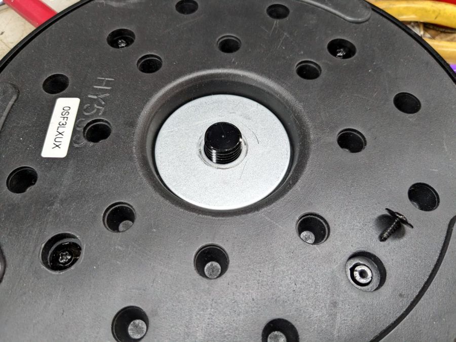
A fender washer atop the weight distributes stress from the pole:
Miroco floor lamp base – weight top washer
Another fender washer on the bottom of the weight lets the nut jam against steel, rather than soft plastic:
Miroco floor lamp base – weight bottom washer
FWIW, the nut is either a perfect 15/16 inch or, more likely, a sloppy 24 mm.
In any event, permanently locking the pole to that socket will also lock the pole to the base, with no way to dismantle the lamp when I must once again repair it.
Perhaps a wrap of PTFE tape on the threads will stiffen it enough?


