Ed Nisley's Blog: Shop notes, electronics, firmware, machinery, 3D printing, laser cuttery, and curiosities. Contents: 100% human thinking, 0% AI slop.
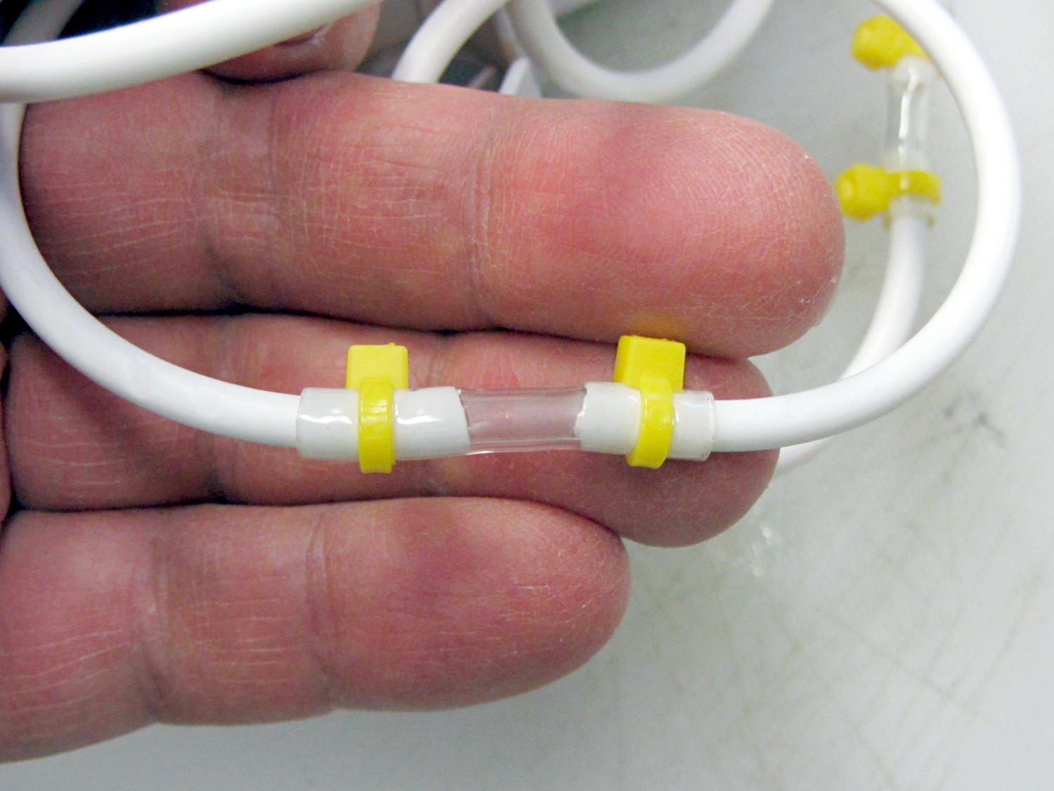
It seems the coiled hose on “water flossers” or “water jet” oral hygene appliances (I can’t even type that with a straight face) lasts about three years, then fails in a spectacular water spray. Mary’s Interplak cleaner just blew a hose, whereupon I discovered that 3/32 inch ID Tygon tubing is a very snug press fit over the 3.8 mm OD white plastic hose:
Patched Interplak tubing
The hose blew out during the early part of a protracted snow storm / cold snap, when driving out for a replacement wasn’t going to happen. This fix, ugly though it may be, has been working well enough that we’ll wait for something else to go wrong.
It’s not clear replacing the entire length of hose with Tygon tubing would work as well, because the rigid hose transmits water pressure pulses from the pump to the tip without much damping. We’re not sure how much that matters and, if the Tygon hack outlasts the OEM hose, maybe we’ll try that.
As you might expect, the hose isn’t a replaceable part. In fact, Interplak doesn’t list any replaceable parts, other than the jet tips, which never seem to wear out…
This is not the Monthly Image I had scheduled for today…
A few weeks ago I reported to my doctor that I had a pressure-sensitive lump in my right breast. This happened the very next day:
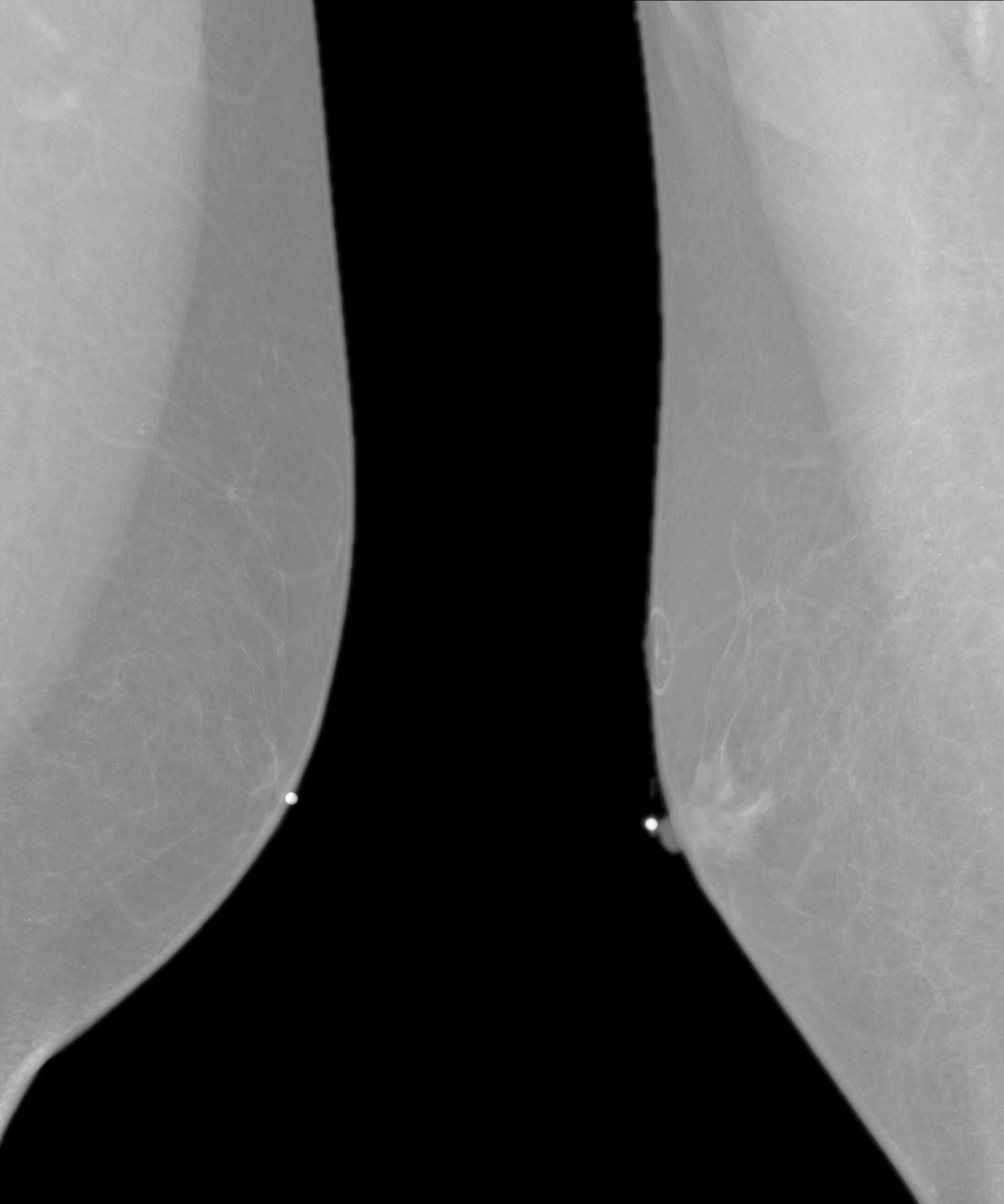
Left-right Mammogram
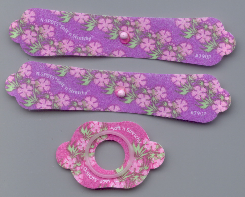
It’s a composite of two mammogram images, of my left and right breasts, respectively, with the small white dots marking the obvious targets and the ring above the right dot surrounding a mole. You will be unsurprised to know that the radio-opaque markers came on cheery flowered stickers:
Given such small numbers, what you see up there on the right is almost certainly an unusually tender and mostly unilateral case of gynecomastia, which was the diagnosis relayed from the radiologist after the imaging. Because things are different for guys, there’s an appointment with an oncologist (yes, she specializes in breast cancer) and, perhaps, some biopsy samples in my immediate future.
They triage the appointment schedule based on radiographic evidence. Fortunately, I’m not on the hot list.
Some browsing with the obvious keywords shows that side effects of the blood pressure dope I was taking last year probably triggered my symptoms, with calcium channel blockers and spironolactone the most directly implicated drugs. It turns out that my blood pressure seems OK without drugs (now that they moved the goal posts for my age bracket, anyway), but we devoted half a year to discovering that nothing produced much of a direct effect and the side effects were completely unacceptable.
Protip: it’s probably not worth reducing a male’s androgen levels just to see if his blood pressure goes down. [sigh]
Back to the usual tech stuff …
Returning home with a CD of digital images in hand, I found that, unlike those older X-ray images, feeding these DICOM images (all sporting informative names like IN000001) into the current version of Imagemagick‘s convert triggers a segfault. Rummaging in the repositories produced a dedicated conversion program:
medcon -f IN* -c png
… which grinds away on the DICOM files and spits out PNG image files with the same names prefixed with an ascending sequence number of the form m000-. A burst of Perl regex line noise removes the prefixes:
rename 's/m[\d]{3}-//' *png
Figuring that out neatly diverted my mind from the Main Topic for a while…
The oncologist says I have a classic, textbook case of gynecomastia; if her med students weren’t on break, she’d use me as an example.
About 10% of males taking spironolactone for blood pressure control develop gynecomastia, typically in only one breast. Absent any other signs, there’s no need for biopsy samples or surgical intervention. The symptoms generally resolve within a year after discontinuing spironolactone.
Should the symptoms persist and become objectionable, treatments include surgery or tamoxifen… but I’m not down with that.]
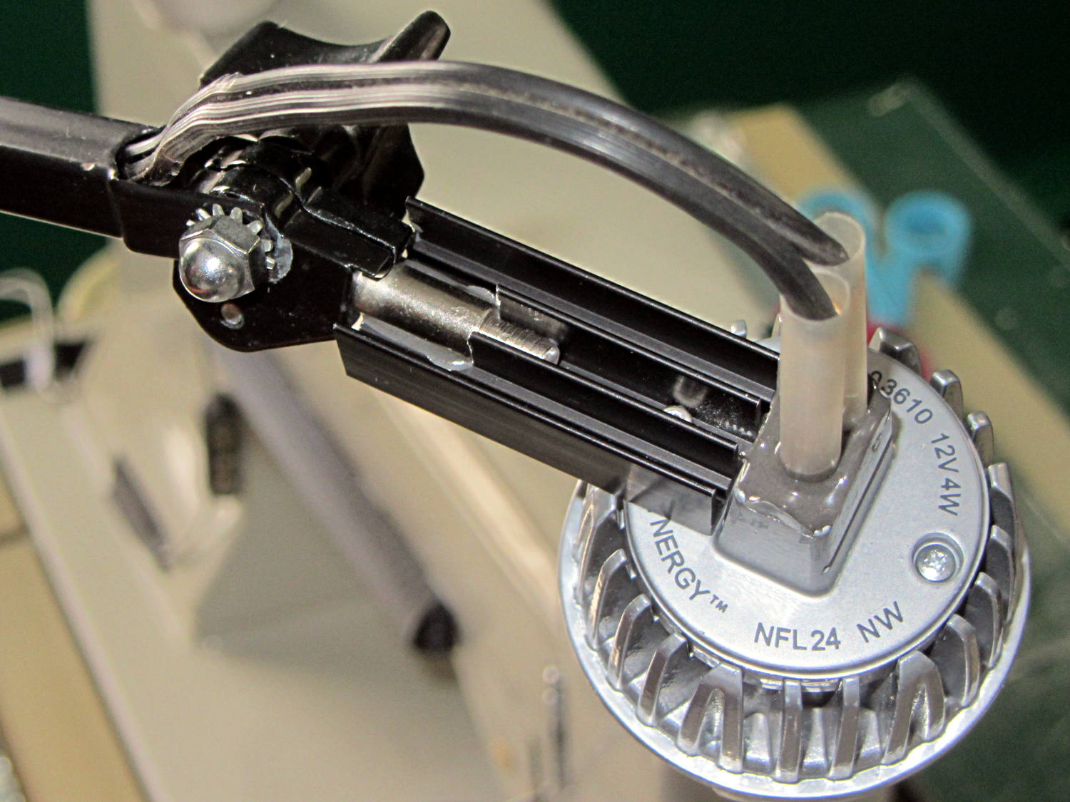
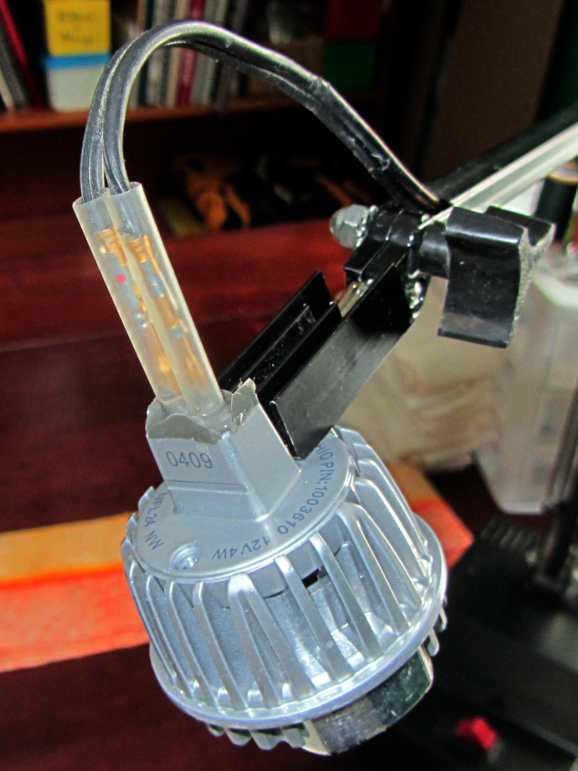
Quite a while ago, I rebuilt a gooseneck shop lamp with an LED floodlight module, the light from which appears in many pictures of the Sherline mill. That module has a sibling that I just combined with a defunct halogen desk lamp to produce a better task light for the bench; the original 12 VAC 50 W transformer now loafs along at 4 W and ballasts the lamp base against tipping.
My initial idea, of course, was a 3D printed adapter from the existing arm hardware to the LED module, but PLA gets droopy at normal high-intensity LED heatsink temperatures. That led to doodling a metal bracket around the LED module flange, which led to pondering how annoying that would be to make, which led to the discovery that the screws holding the LED plug to the heatsink were ordinary M2x0.4 Philips head, which suggested I could just screw a bracket to the back of the module, which brought a recently harvested aluminum heatsink to hand, which led to the discovery that the tip of the pivot screw fit perfectly between the fins, which …
Shortly thereafter, I milled off the central fins to fit the shaft of the pivot screw, introduced the heatsink to Mr. Disk Sander to bevel the bottom, sawed the threads off the pivot, press-fit the two together, drilled a 2 mm cross-hole into the pivot, buttered it all up with epoxy, jammed a short M2 screw into the cross hole, and let the whole mess cure:
Desk Lamp LED Adapter – top view
The lamp modules were a surplus find, with one pin clipped nearly flush to the insulator. I soldered a pair of the same male pins as in the battery holders, with the matching female pins as a crude connector. The unshrunk heatstink tubing isn’t lovely, but got us to First Light:
Desk Lamp LED Adapter – front view
The original counterweight is, of course, much too heavy for the dinky LED module, so I’ll drill the mounting hole for the vertical arm further back on the beam to get another foot of reach. That will require more wire between the transformer to the lamp, soooo the connectors might just become soldered joints.
As you can tell from the background, Mary snatched the lamp from my hands and put it to immediate use in The Quilting Room.
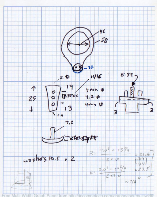
The original doodles bear no resemblance to the final product, but do have some key dimensions that (having discarded the unused hardware) I’ll likely never need again.
The pivot between the arm and the lamp housing, with an idea for the LED holder:
Desk Lamp Bracket Dimensions – doodle
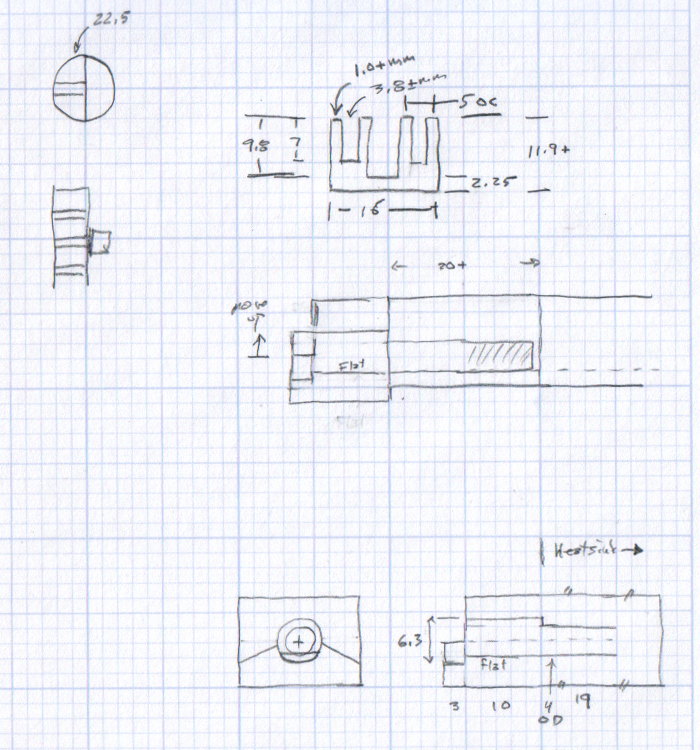
Details of the repurposed heatsink and the pivot bolt, with a block that never got built:
Although commenting out an undesired variable isn’t fashionable, OpenSCAD doesn’t have a practical mechanism to set specific values based on a control variable:
if-then-else deals with geometric objects
(boolean)?when_true:when_false (the ternary operator) doesn’t scale well
You could, of course, depend on OpenSCAD’s behavior of using the last (in syntactic order) instance of a “variable”, but IMHO that’s like depending on semantic whitespace.
In any event, the rest of the block builds itself around those three values by recomputing all of its dimensions.
The Browning OEM block looks like this:
Browning Hi-Power Magazine Block – solid model – BHP OEM
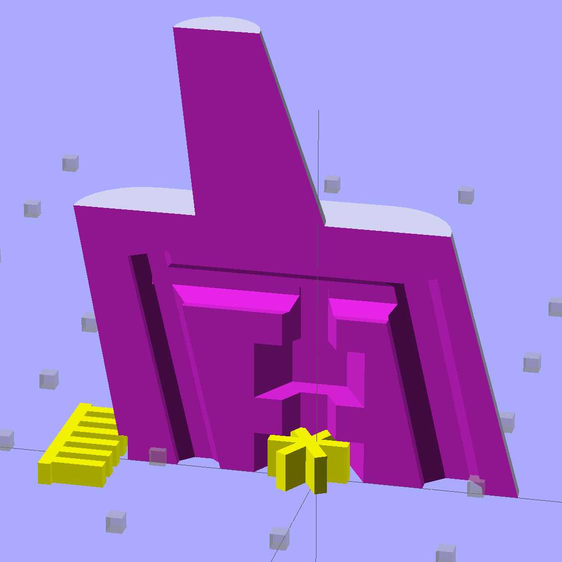
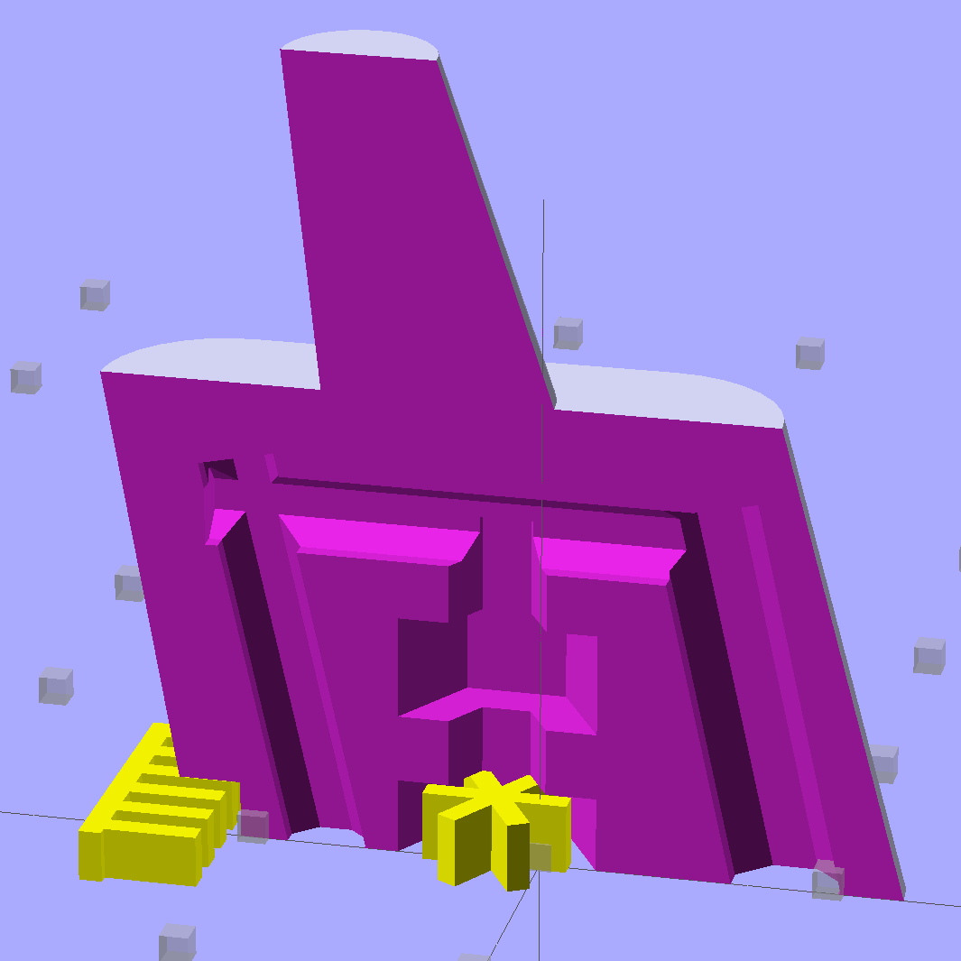
The Generic floorplate has a much larger spring retaining crimp, so the block has far more overhang:
Browning Hi-Power Magazine Block – solid model – Generic 1
As before, the yellow widgets are built-in support structures separated from the main object by one thread thickness and width. That seems to maintain good vertical tolerance and allow easy removal; the structures snap free with minimal force. A closeup look shows the gaps:
Browning Hi-Power Magazine Block – solid model – Generic 1 – support detail
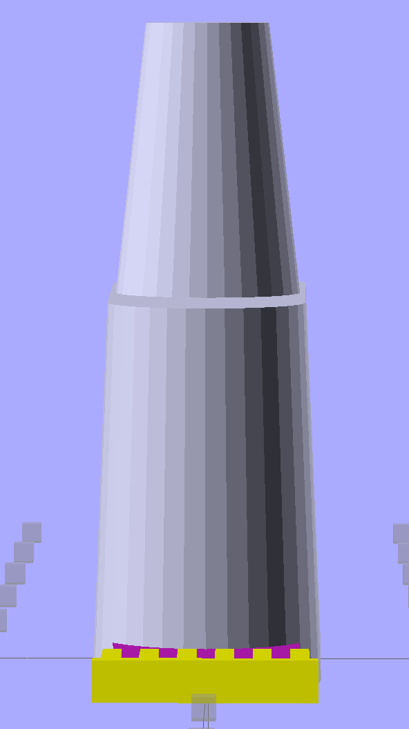
The main shape now has a 2 mm taper to ease the magazine spring past the upper edge of the block. The horn remains slightly inset from the side walls to ensure that the whole thing remains manifold:
Browning Hi-Power Magazine Block – solid model – Generic 1 – whole end
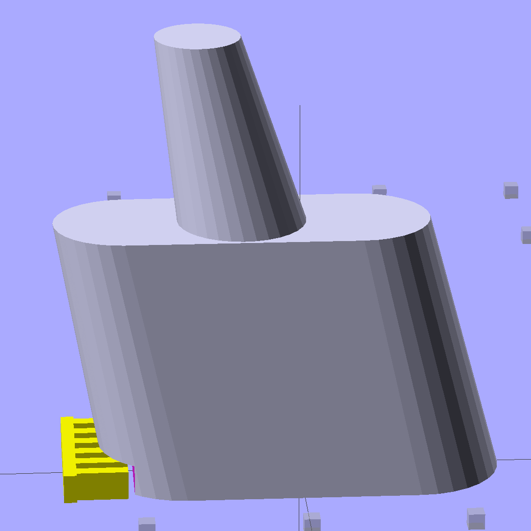
The whole object looks about the same, though:
Browning Hi-Power Magazine Block – solid model – Generic 1 – whole side
The shape descends from the geometry I used for the stainless steel block, with the additional internal channel (on the right in the models) to be filled with steel-loaded epoxy during assembly. That should make the whole block sufficiently robust that you must destroy the floorplate and distort the spring to get it out; wrecking the magazine’s innards should count as not “readily” modifiable.
Some destructive testing seems to be in order…
The OpenSCAD source code:
// Browning Hi-Power Magazine Plug
// Ed Nisley KE4ZNU December 2013
// February 2014 - easier customization for different magazine measurements
Layout = "Whole"; // Whole Show Split
// Whole = upright for steel or plastic
// Show = section view for demo, not for building
// Split = laid flat for plastic show-n-tell assembly
AlignPins = true && (Layout == "Split"); // pins only for split show-n-tell
Support = true && (Layout != "Split"); // no support for split, optional otherwise
// Define magazine measurements
//BlockData =  [-0.5, 1.5, 11.5];	// Browning OEM
BlockData = [-1.5, 2.0, 9.0];		// Generic 1

SCREWOFFSET = 0;
CRIMPHEIGHT = 1;
CRIMPDISTANCE = 2;
//- Extrusion parameters must match reality!
// Print with 2 shells and 3 solid layers
ThreadThick = 0.20;
ThreadWidth = 0.40;
HoleWindage = 0.2;
Protrusion = 0.1; // make holes end cleanly
function IntegerMultiple(Size,Unit) = Unit * ceil(Size / Unit);
//----------------------
// Dimensions
Angle = 12.5; // from vertical
SpringID = 10.3; // magazine spring curvature (measure with drill shank)
SpringRadius = SpringID / 2;
Taper = 2.0; // total taper toward top
Length = 24.5; // front-to-back perpendicular to magazine shaft
Height = 17.0; // bottom-to-top, parallel to magazine shaft
RectLength = Length - SpringID; // block length between end radii
HornBaseOD = 8.0; // fits between follower pegs to prevent shortening
HornTipOD = 5.0;
HornAddTip = (HornTipOD/2)*tan(Angle);
HornAddBase = (HornBaseOD/2)*tan(Angle);
HornAddLength = HornAddTip + HornAddBase + 2*Protrusion;
HornLength = 12.0; // should recompute ODs, but *eh*
ScrewOD = 3.0 - 0.25; // screw hole dia - minimal thread engagement
ScrewLength = Height - 5.0;
ScrewOffset = BlockData[SCREWOFFSET]; // ... from centerline on XY plane
NutOD = 5.8; // hex nut dia across flats
NutThick = 2.4; // ... generous allowance for nut
NutTrapLength = 1.5*NutThick; // allow for epoxy buildup
NutTrapBaseHeight = 5.0; // ... base height from floor plate
CrimpHeight = IntegerMultiple(BlockData[CRIMPHEIGHT],ThreadThick); // vertical clearance for spring crimp tab on base plate
CrimpDistance = BlockData[CRIMPDISTANCE]; // ... clip to screw hole center
CrimpOffset = -(CrimpDistance - ScrewOffset); // ... horizontal from centerline
SupportLength = 4.0; // length of support struts under Trim
SupportWidth = IntegerMultiple(0.9*SpringID,4*ThreadWidth); // ... size needed for platform adhesion
SupportThick = CrimpHeight - ThreadThick; // ... clearance for EZ removal
VentDia = 2.5; // air vent from back of screw recess
//VentOffset = CrimpOffset + VentDia/2 + 5*ThreadWidth;
VentOffset = -(NutOD + 4*ThreadWidth);
VentLength = ScrewLength + VentDia;
RecessDia = 3.5; // additional air vent + weight reduction
RecessLength = ScrewLength + RecessDia/2; // ... internal length
RecessOffset = Length/2 - RecessDia/2 - 5*ThreadWidth; // ... offset from centerline
PinOD = 1.72; // alignment pins
PinLength = 4.0;
PinInset = 0.6*SpringRadius; // from outside edges
echo(str("Alignment pin length: ",PinLength));
NumSides = 8*4; // default cylinder sides
Offset = 5.0/2; // from centerline for build layout
//----------------------
// Useful routines
function Delta(a,l) = l*tan(a); // incremental length due to angle
// Locating pin hole with glue recess
// Default length is two pin diameters on each side of the split
module LocatingPin(Dia=PinOD,Len=0.0) {
PinLen = (Len != 0.0) ? Len : (4*Dia);
translate([0,0,-ThreadThick])
PolyCyl((Dia + 2*ThreadWidth),2*ThreadThick,4);
translate([0,0,-2*ThreadThick])
PolyCyl((Dia + 1*ThreadWidth),4*ThreadThick,4);
translate([0,0,-(Len/2 + ThreadThick)])
PolyCyl(Dia,(Len + 2*ThreadThick),4);
}
module PolyCyl(Dia,Height,ForceSides=0) { // based on nophead's polyholes
Sides = (ForceSides != 0) ? ForceSides : (ceil(Dia) + 2);
FixDia = Dia / cos(180/Sides);
cylinder(r=(FixDia + HoleWindage)/2,
h=Height,
$fn=Sides);
}
module ShowPegGrid(Space = 10.0,Size = 1.0) {
Range = floor(50 / Space);
for (x=[-Range:Range])
for (y=[-Range:Range])
translate([x*Space,y*Space,Size/2])
%cube(Size,center=true);
}
//----------------------
// The magazine block
module Block(SectionSelect = 0) {
CropHeight = Height*cos(Angle); // block height perpendicular to base
echo(str("Perpendicular height: ",CropHeight));
difference() {
union() {
intersection() {
rotate([Angle,0,0])
hull() {
for (i=[-1,1])
translate([0,i*RectLength/2,-((Length/2)*sin(Angle) + Protrusion)])
cylinder(r1=SpringRadius,r2=(SpringRadius - Taper/2),
h=(Height + 2*(Length/2)*sin(Angle) + 2*Protrusion),
$fn=NumSides);
}
translate([0,0,CropHeight/2])
cube([2*SpringID,3*Length,CropHeight],center=true);
}
translate([0,-Height*sin(Angle),Height*cos(Angle)])
resize([(SpringID - Taper),0,0])
intersection() {
rotate([Angle,0,0])
translate([0,0,-(HornAddBase + Protrusion)])
cylinder(r1=HornBaseOD/2,
r2=HornTipOD/2,
h=(HornLength + HornAddLength + Protrusion),
$fn=NumSides);
cube([2*SpringID,Length,2*(HornLength*cos(Angle) + Protrusion)],center=true);
}
}
translate([0,ScrewOffset,-Protrusion]) // screw
rotate(180/6)
PolyCyl(ScrewOD,(ScrewLength + Protrusion),6);
translate([0,ScrewOffset,NutTrapBaseHeight]) // nut trap in center
rotate(180/6)
PolyCyl(NutOD,NutTrapLength,6);
translate([0,ScrewOffset,-Protrusion]) // nut clearance at base
rotate(180/6)
PolyCyl(NutOD,(1.1*NutThick + Protrusion),6);
translate([SpringID/2,CrimpOffset,-Protrusion])
rotate(180)
cube([SpringID,Length,(CrimpHeight + Protrusion)],center=false);
if (AlignPins) // alignment pins
if (true)
translate([0,-CropHeight*tan(Angle),CropHeight])
rotate([0,90,0]) rotate(45 + Angle)
LocatingPin(PinOD,PinLength);
else
for (i=[-1,1]) // cannot use these with additional vents * channels
rotate([Angle,0,0])
translate([0,
(i*((Length/2)*cos(Angle) - PinInset)),
(CropHeight/2 - i*2*PinInset)])
rotate([0,90,0]) rotate(45 - Angle)
LocatingPin(PinOD,PinLength);
translate([0,(ScrewOffset + 1.25*NutOD),ScrewLength]) // air vent
rotate([90,0,0]) rotate(180/8)
PolyCyl(VentDia,3*NutOD,8);
translate([0,VentOffset,-(VentDia/2)*tan(Angle)])
rotate([Angle,0,0]) rotate(180/8)
PolyCyl(VentDia,VentLength,8);
translate([0,RecessOffset,0]) // weight reduction recess
rotate([Angle,0,0]) rotate(180/8)
translate([0,0,-((RecessDia/2)*tan(Angle))])
PolyCyl(RecessDia,(RecessLength + (RecessDia/2)*tan(Angle)),8);
if (SectionSelect == 1)
translate([0*SpringID,-2*Length,-Protrusion])
cube([2*SpringID,4*Length,(Height + HornLength + 2*Protrusion)],center=false);
else if (SectionSelect == -1)
translate([-2*SpringID,-2*Length,-Protrusion])
cube([2*SpringID,4*Length,(Height + HornLength + 2*Protrusion)],center=false);
}
SupportSlots = (SupportWidth / (4*ThreadWidth)) / 2; // SupportWidth is multiple of 4*ThreadWidth
if (Support)
color("Yellow") {
translate([0,(CrimpOffset - SupportLength/2),SupportThick/2])
difference() {
translate([0,-ThreadWidth,0])
cube([(SupportWidth - Protrusion),SupportLength,SupportThick],center=true);
for (i=[-SupportSlots:SupportSlots])
translate([i*4*ThreadWidth + 0*ThreadWidth,ThreadWidth,0])
cube([(2*ThreadWidth),SupportLength,(SupportThick + 2*Protrusion)],center=true);
}
translate([0,ScrewOffset,0])
for (j=[0:5]) {
rotate(30 + 360*j/6)
translate([(NutOD/2 - ThreadWidth)/2,0,(1.1*NutThick - ThreadThick)/2])
color("Yellow")
cube([(NutOD/2 - ThreadWidth),
(2*ThreadWidth),
(1.1*NutThick - ThreadThick)],
center=true);
}
}
}
//-------------------
// Build it...
ShowPegGrid();
if (Layout == "Show")
Block(1);
if (Layout == "Whole")
Block(0);
if (Layout == "Split") {
translate([(Offset + Length/2),Height/2,0])
rotate(90) rotate([0,-90,-Angle])
Block(-1);
translate([-(Offset + Length/2),Height/2,0])
rotate(-90) rotate([0,90,Angle])
Block(1);
}
Drill 3 mm hole in the center of the inner plate boss
Wire-brush the plate to remove the black coating
Mount a nut on a spring-loaded screw
Apply paste flux under the nut
Align snippets of silver solder under the nut
Fire the propane torch!
The flux is Ultra-Flux, a nasty concoction intended for silver solder, which in this case is Brownell’s Silvaloy 355 in strip form. Despite the name, it’s 56% silver and has much higher strength than soft tin-lead solder. Although I haven’t done any destructive testing, a good joint will be stronger than the base metals.
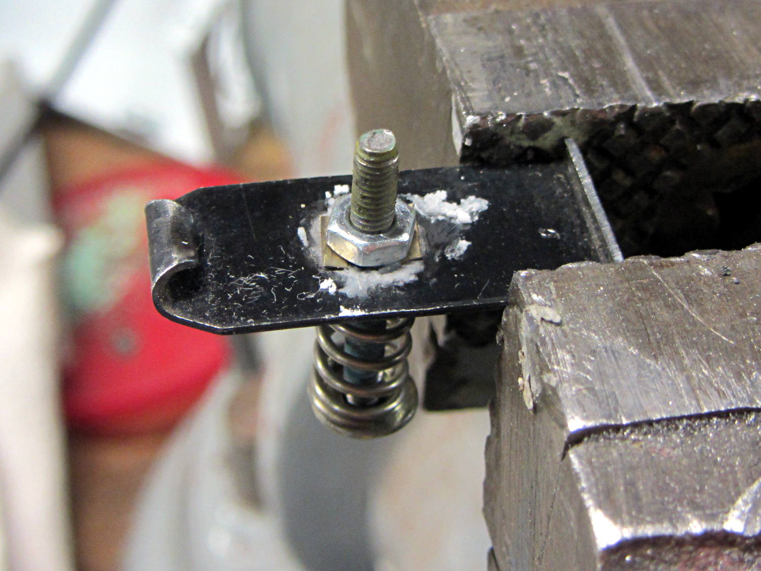
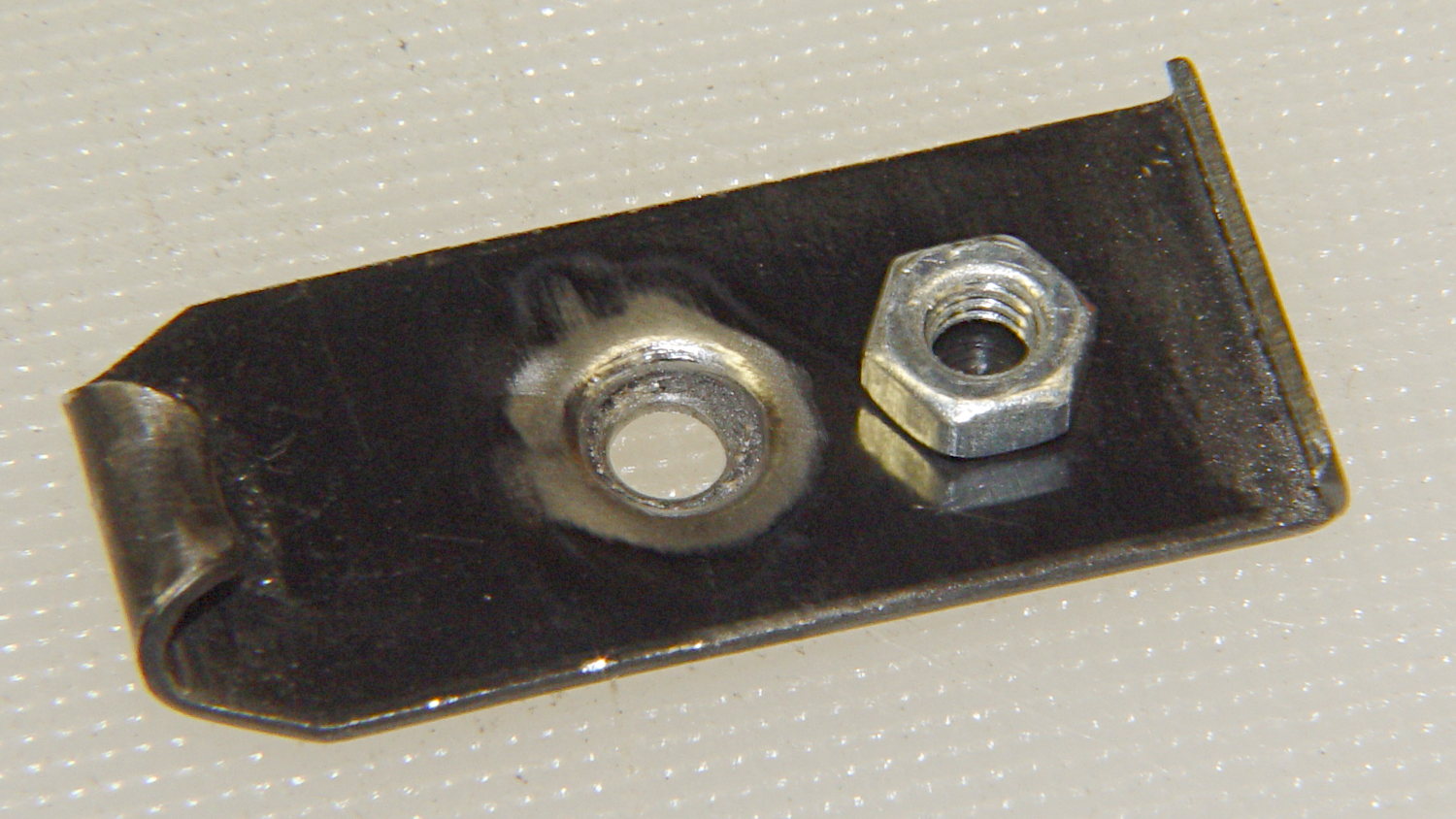
The setup before soldering the first nut:
Browning floor plate – nut brazing setup
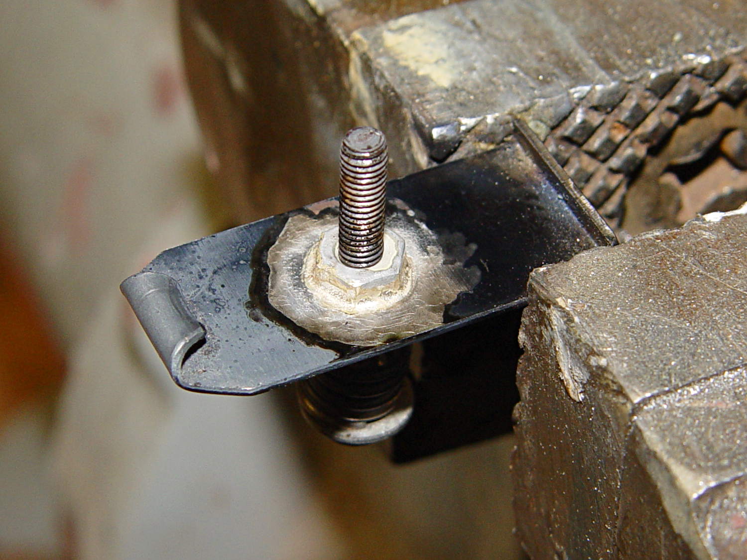
The spring holds the nut in the proper position, lets it settle straight down as the flux liquefies and the solder melts, then holds it flat against the floor plate to ensure a proper bond and a good fillet. I coated the screw with Tix Anti-Flux to ensure it didn’t become one with the nut.
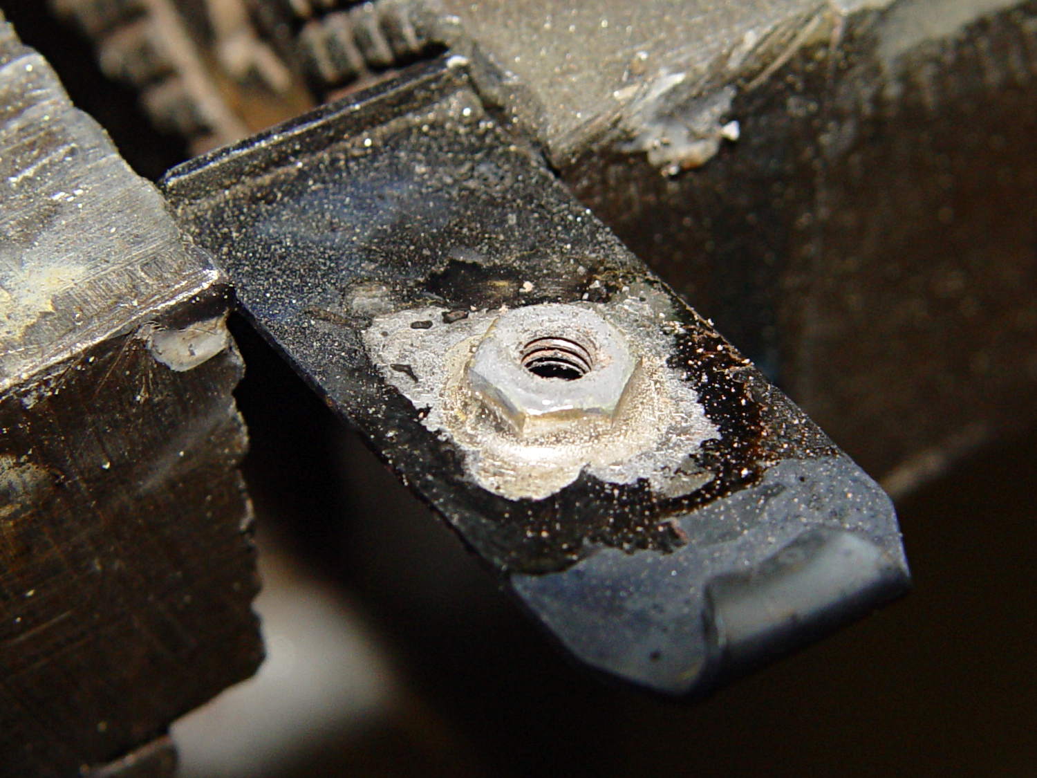
The same joint after heating:
Browning floor plate – nut brazed 1
The garish red apparently comes from the Anti-Flux; the screw never got more than dull red and was cool by the time I shut off the torch and fiddled with the camera.
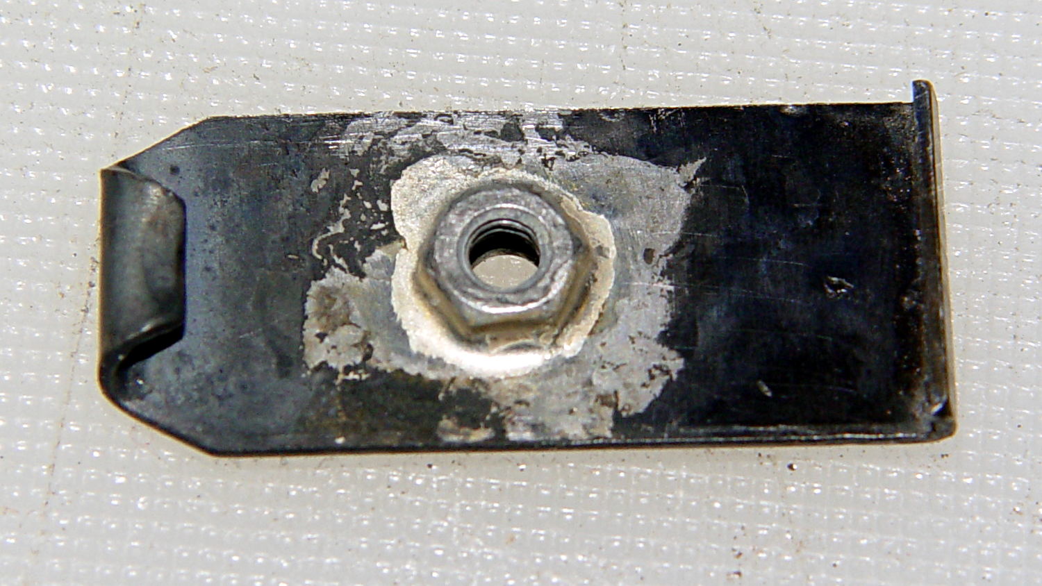
However, the rear of that first nut didn’t get a suitable fillet, so I reheated and removed it to reveal a section where the flux didn’t clean the steel and the solder didn’t flow:
Browning floor plate – nut 1 test
Note that the area below the middle of the nut can’t have a full solder joint, because the nut sits over the depression that forms the boss, thusly:
Browning Hi-Power magazine – drilled floor plate
The solder fillet will, however, surround the nut and bond the ring near the flat part of the plate.
Properly cleaning and brushing that area produced a better joint under a new nut:
Browning floor plate – nut brazed 1a
The fillet now extends all the way around the nut, as it should:
Browning floor plate – nut brazed 1a no screw
The crusty appearance comes from the flux residue, which comes off easily in a bath of boiling water to reveal a smooth fillet:
Browning floor plate – defluxed
With cleanliness & good conduct in mind, the remainder of the floor plates brazed smoothly, with good results on the first heating:
Browning floor plate – nut brazed 2
Repeated heating took the starch right out of that poor spring, though…
With brazed plate in hand, the next step will be fitting suitable blocks to the individual floor plates.
(*) My state senator and assemblyperson (or, more exactly, their staffers) have been totally unhelpful in resolving the definition of “readily” as used in the legislation, to the extent that they don’t respond to emails asking about the result of meetings they said they attended with, e.g., State Police counsels, to get more information.
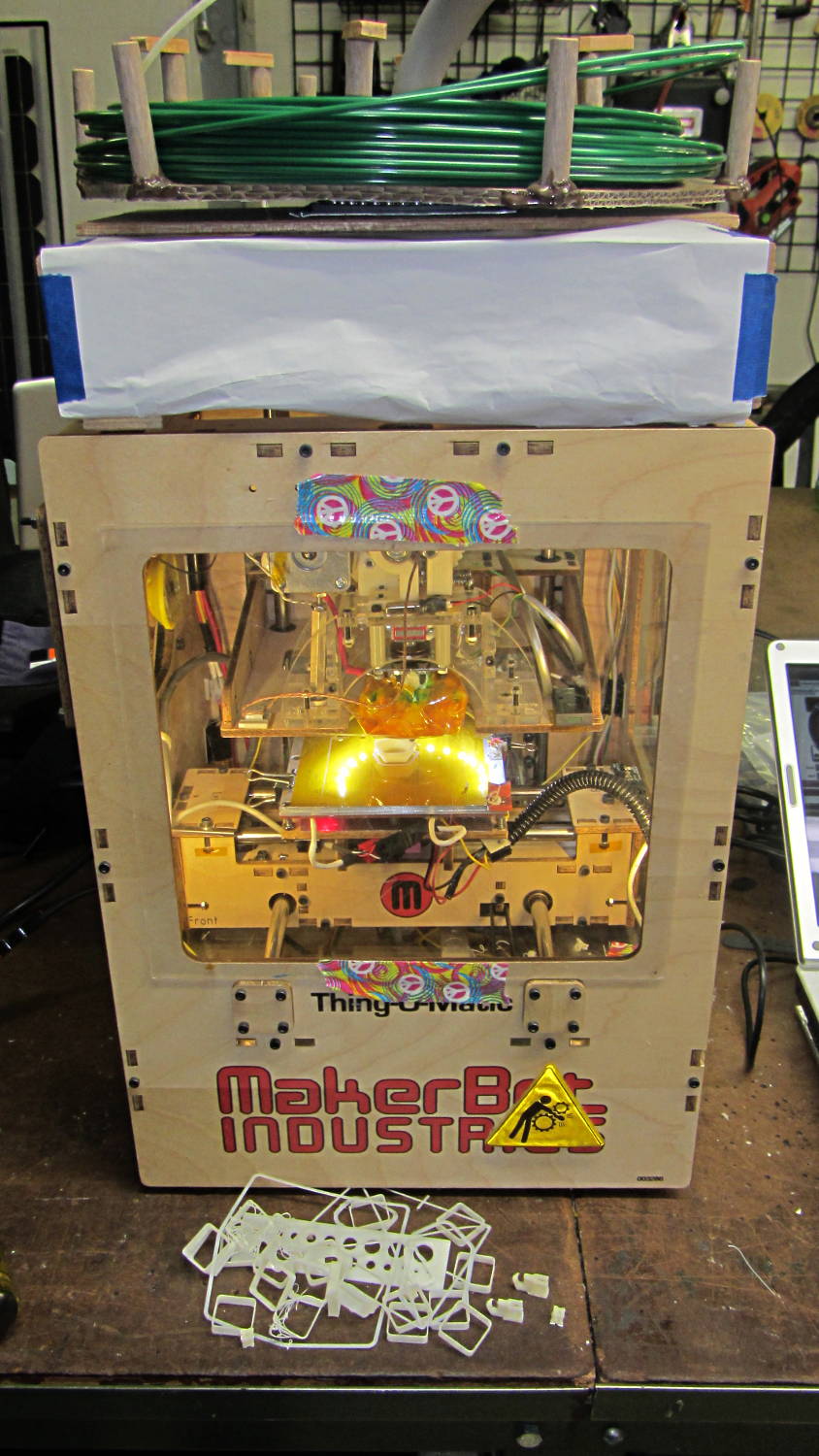
The saga of rebuilding and reconfiguring my old Thing-O-Matic around an Azteeg X3 controller and Marlin software at Squidwrench continues apace:
TOM286 – with calibration scrap
A major benefit of doing this at the group meetings has been showing everybody that 3D printing isn’t a mass-production process. The pile of calibration objects includes an inordinate number of those thinwall open boxes that take about five minutes each:
3D printed calibration scrap
But it’s producing reasonable quality stuff again:
TOM286 – First Dodecahedron
The loose threads on the outward sloping sides of that dodecahedron show that I forgot to lower the temperature after a bit of trouble with adhesion to the platform; the problem turned out to be an interaction between Slic3r’s minimum layer time and minimum printing speed settings that I didn’t notice.
A disadvantage of doing this at the group meetings is that two or three hours of tweaking and printing, once a week, draws the whole process out far longer than anyone else expected… [grin]
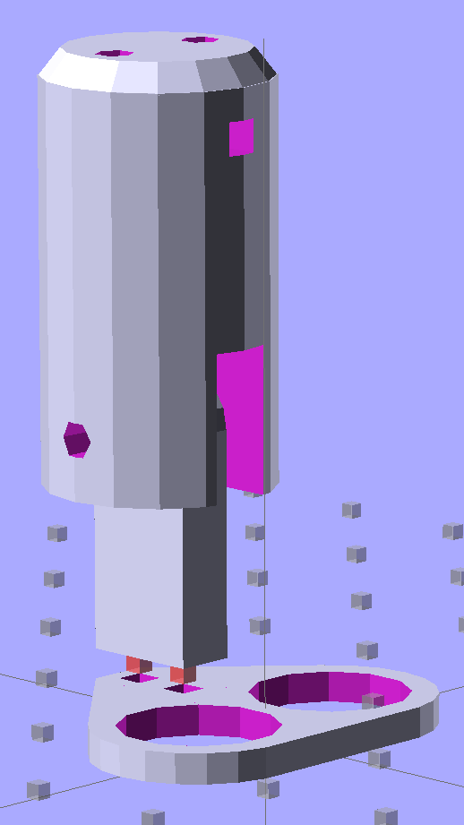
Some trial fitting with the prototype showed that there’s no possible way to route the connections through the socket, no matter how much I wanted that to happen, so I rotated the body to align the LEDs with the socket pin slots:
Sears Lamp LED Adapter – Show view
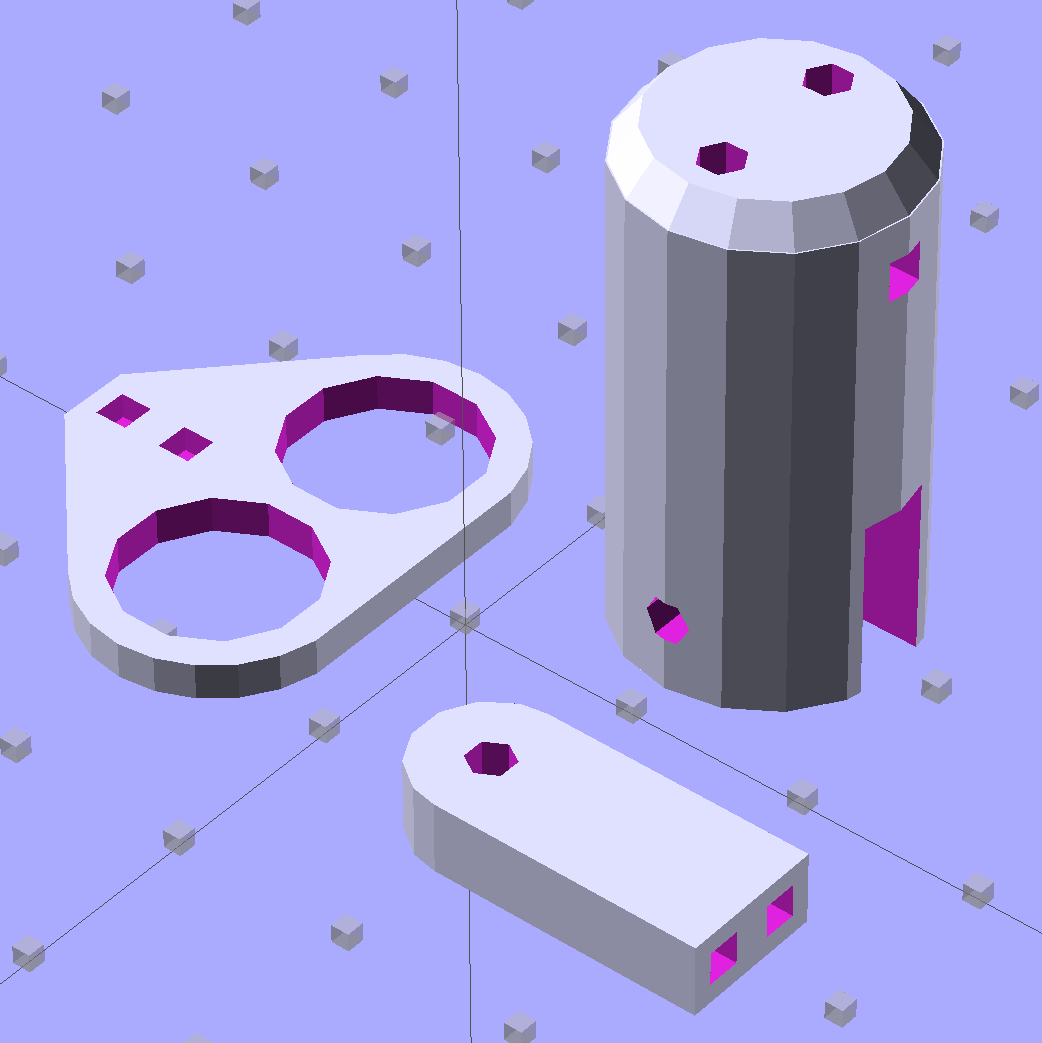
The body now builds with the flat end down, so the overall finish should be better:
Sears Lamp LED Adapter – Build view
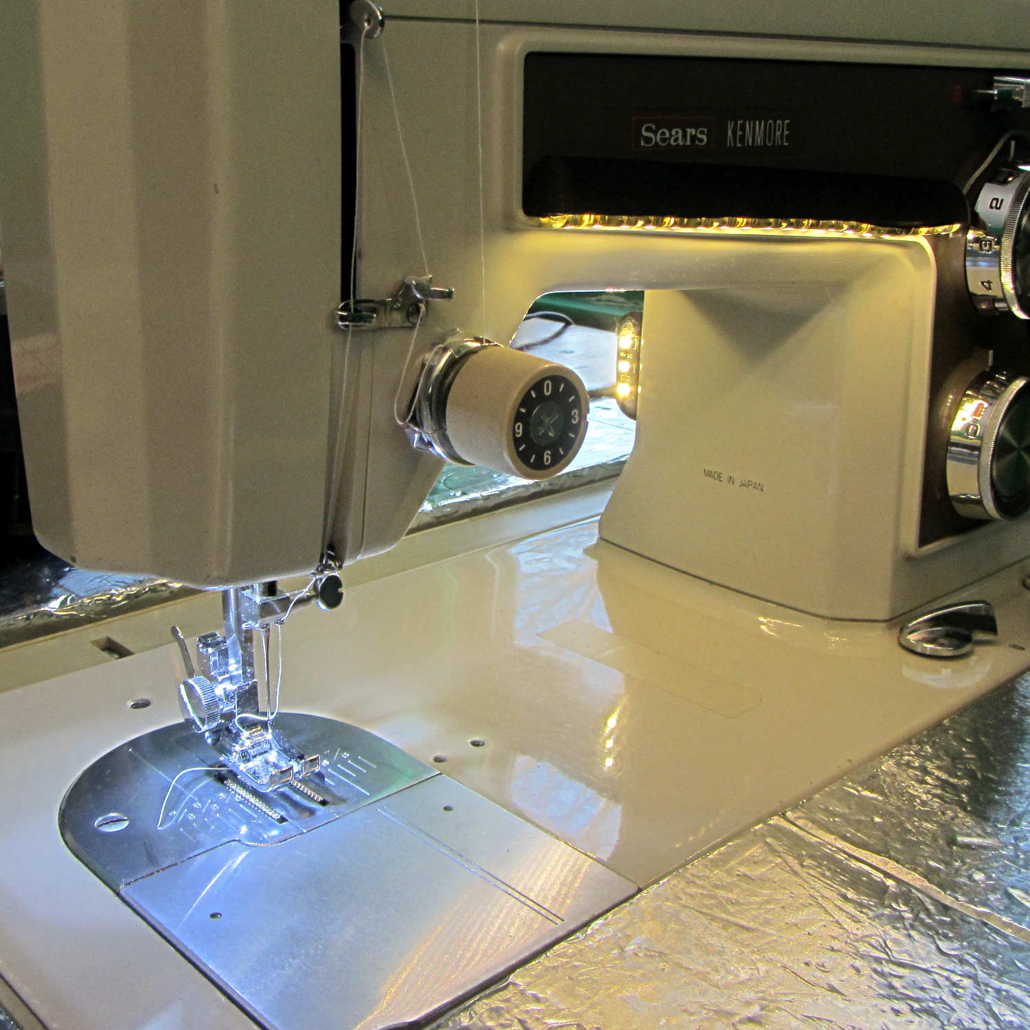
A test run shows why I really, really wanted cool white LEDs in the strips over the arm:
Kenmore 158 Sewing Machine – mixed LED lighting
The LED mount doesn’t have quite enough room inside the end cap for the holder to tilt as I wanted; the two 10 mm LEDs can be about 10 mm lower and slightly closer to the shaft driving the needle, which is what this rapid prototyping stuff is all about. Scrapping the existing lamp socket and (120 VAC!) wiring seems the best way to make this more useful.
Early reports on the arm LEDs indicate a requirement for more light, so the next iteration of those mounts will put two strips side-by-side…