Ed Nisley's Blog: Shop notes, electronics, firmware, machinery, 3D printing, laser cuttery, and curiosities. Contents: 100% human thinking, 0% AI slop.
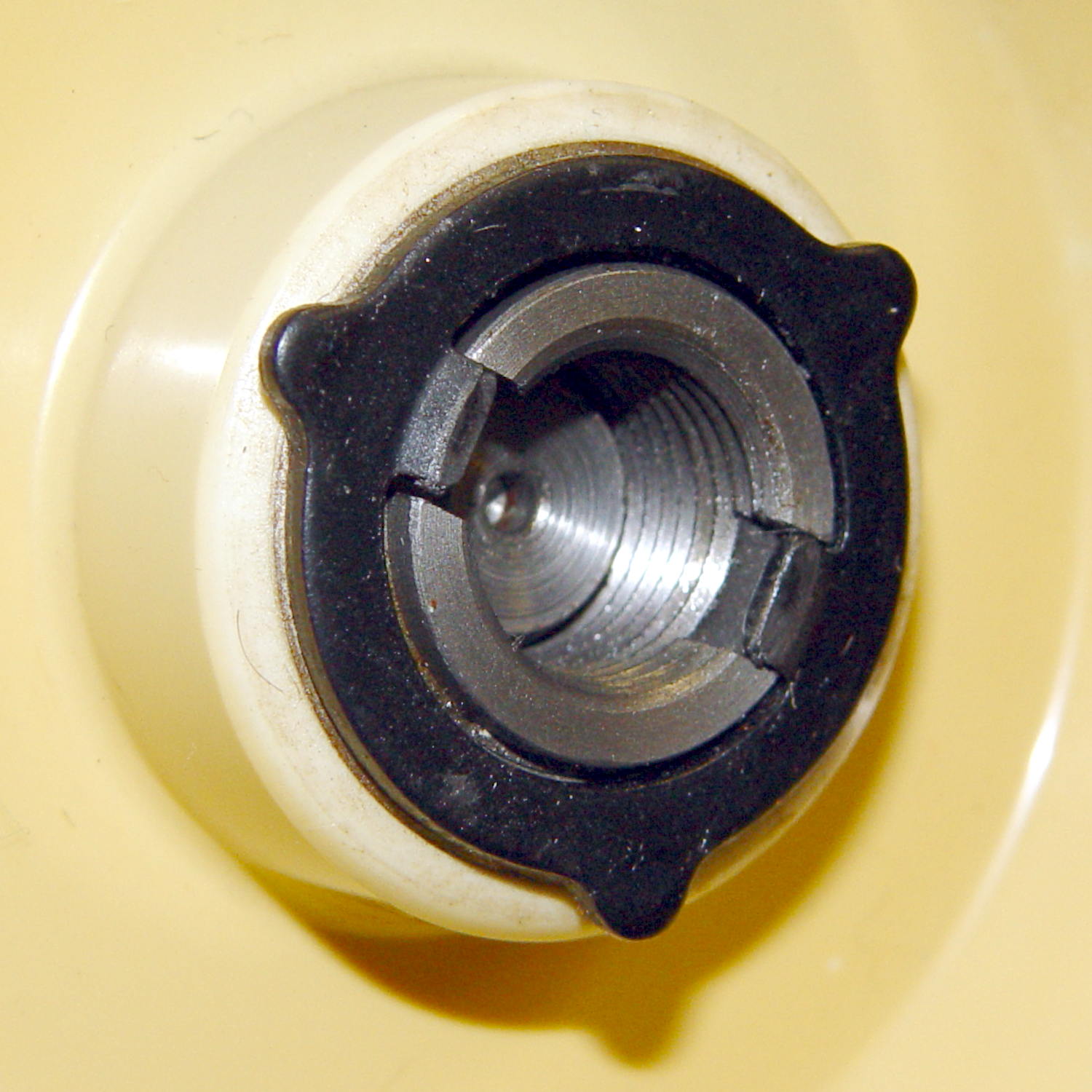
The handwheel on the Kenmore Model 158 sewing machine has a shiny knurled knob in the middle:
Kenmore 158 handwheel – knob
Turning the knob clockwise screws the knob inward and clamps a friction clutch that locks the handwheel to the main shaft; the motor belt drives the handwheel, the handwheel drives the shaft, and the shaft drives everything inside the sewing machine.
Remove the small screw, turn the knob counterclockwise to remove it, and you see the clutch:
Kenmore 158 – handwheel clutch – detail
Yes, the black stamped metal part is the clutch.
Those three projections around the exterior limit the knob’s travel to a bit under 1/3 turn, with the little screw you just removed traveling between two of the projections. When you reinstall the knob:
Turn it until it’s snug
Insert and tighten the screw
Done!
The two dogs in the middle project outward from the shaft notches: the bases engage the notches and the tips bear on the knob’s inner surface. Tightening the knob pushes on the dogs, presses the clutch against the handwheel, and locks everything together.
It’s entirely possible to install the clutch backwards and, while it’ll come pretty close to working, it’s not quite right.
Update: A note from a reader suggests the machine can struggle along with a backwards clutch for a while:
Just wanted to say thanks for the post on the Kenmore 158 clutch washer. I was trying to hem some jeans, and the clutch was slipping going through the thicker parts. Figured out the washer was on backwards from your post. Now, it works properly.
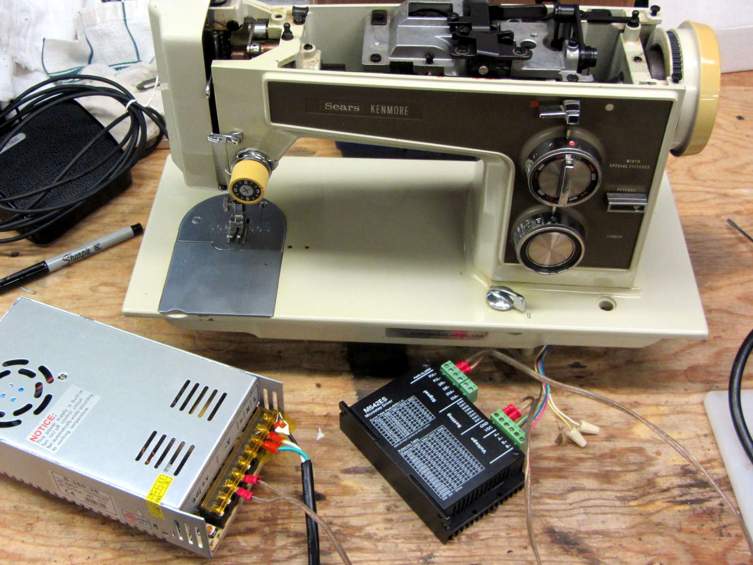
Having a NEMA 23 stepper fit almost exactly into the spot vacated by the sewing machine’s AC motor was too good to pass up:
Kenmore 158 – NEMA 23 stepper – on adapter
So I wired a power supply to an M542 stepper driver brick, connected the pulse output of a function generator to the brick’s STEP inputs, swapped motor leads until it turned the proper direction (CCW as seen from the shaft end), and turned the function generator knob:
Kenmore 158 – NEMA 23 stepper test
The object was to find the step frequency where the motor stalls, for various winding currents and supply voltages. The motor won’t have enough torque to actually stitch anything near the dropout speed, but this will give an indication of what’s possible.
With a 24 V DC supply and 1/8 microstepping (40 k step/s = 1470 RPM):
1.00 A = 11 k step/s
1.91 A = 44 k/s
2.37 A = 66 k/s
3.31 A = 15 k/s
With a 36 V DC supply and 1/8 microstepping:
1.91 A = 70 k/s
3.31 A = 90 k/s
With a 36 V DC supply and 1/4 microstepping (40 k step/s = 2900 RPM):
1.91 A = 34 k/s
2.37 A = 47 k/s
2.84 A = 47 k/s
3.31 A = 48 k/s
The motor runs faster with a higher voltage supply, which is no surprise: V = L di/dt. A higher voltage across the winding drives a faster current change, so each step can be faster.
The top speed is about 3500 RPM; just under that speed, the motor stalls at the slightest touch. That’s less than half the AC motor’s top speed under a similarly light load and the AC motor still has plenty of torque to spare.
90 k step/s at 1/8 microstepping = 11 k full step/s = crazy fast. Crosscheck: 48 k step/s at 1/4 microstepping = 12 k full step/s. The usual dropout speed for NEMA 23 steppers seems to be well under 10 k full step/s, but I don’t have a datasheet for these motors and, in any event, the sewing machine shaft provides enough momentum to keep the motor cruising along.
One thing I didn’t expect: the stepper excites howling mechanical resonances throughout its entire speed range, because the adapter plate mounts firmly to the cast aluminum frame with absolutely no damping anywhere. Mary ventured into the Basement Laboratory to find out what I was doing, having heard the howls upstairs across the house.
She can also hear near-ultrasonic stepper current chopper subharmonics that lie far above my audible range, so even if the stepper could handle the speed and I could damp the mechanics, it’s a non-starter for this task.
Given that the AC motor runs on DC, perhaps a brute-force MOSFET “resistive” control would suffice as a replacement for the carbon disk rheostat in the foot pedal. It’d take some serious heatsinking, but 100 V (or less?) at something under 1 A and intermittent duty doesn’t pose much of a problem for even cheap surplus MOSFETs these days.
That would avoid all the electrical and acoustic noise associated with PWM speed control, which counts as a major win in this situation. Wrapping a speed control feedback loop around the motor should stiffen up its low end torque.
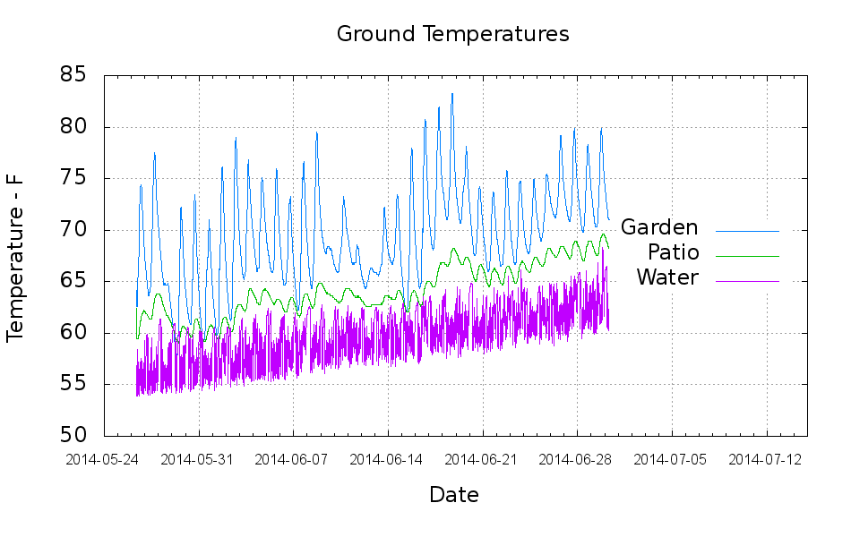
The “Garden” trace comes from a waterproof Hobo datalogger buried a few inches underground, beneath a thick layer of chipped leaf mulch. The “Patio” trace comes from the center of the cramped space below the concrete patio, buried flush with the bare dirt floor. The “Water” trace is the temperature at the incoming water pipe from the town water main, which passes 150 feet under the front yard.
Calculated eyeballometrically, the temperature rose 7 °F in about a month.
The datalogger in the garden came from the “cold cellar” veggie storage buckets, so I don’t have a year-long record. On the other paw, it looks like the patio temperature will be a pretty good proxy for the minimum garden temperature.
I hand-cleaned the Hobo CSV files and fed the results into a Gnuplot script that’s replete with the cruft of ages:
#!/bin/sh
#-- overhead
export GDFONTPATH="/usr/share/fonts/truetype/"
ofile=Temperatures.png
echo Output file: ${ofile}
#-- do it
gnuplot << EOF
#set term x11
set term png font "arialbd.ttf" 18 size 950,600
set output "${ofile}"
set title "Ground Temperatures"
set key noautotitles right center
unset mouse
set bmargin 4
set grid xtics ytics
set timefmt "%m/%d/%Y %H:%M:%S"
set xdata time
set xlabel "Date"
set format x "%Y-%m-%d"
set xrange [:"07/15/2014"]
set xtics font "arial,12"
#set mxtics 2
#set logscale y
#set ytics nomirror autofreq
set ylabel "Temperature - F"
#set format y "%4.0f"
#set yrange [30:90]
#set mytics 2
#set y2label "right side variable"
#set y2tics nomirror autofreq 2
#set format y2 "%3.0f"
#set y2range [0:200]
#set y2tics 32
#set rmargin 9
set datafile separator ","
#set label 1 "Garden"     at "05/31/2014",25 left font "arialbd,10" tc lt 3
#set arrow from 2.100,110 to 2.105,103 lt 1 lw 2 lc 0
plot	\
    "Garden.csv" using 2:3 with lines lt 3 lw 1 title "Garden",\
    "Patio.csv"  using 2:3 with lines lt 2 lw 1 title "Patio",\
    "Water.csv"  using 2:5 with lines lt 4 lw 1 title "Water",\

EOF
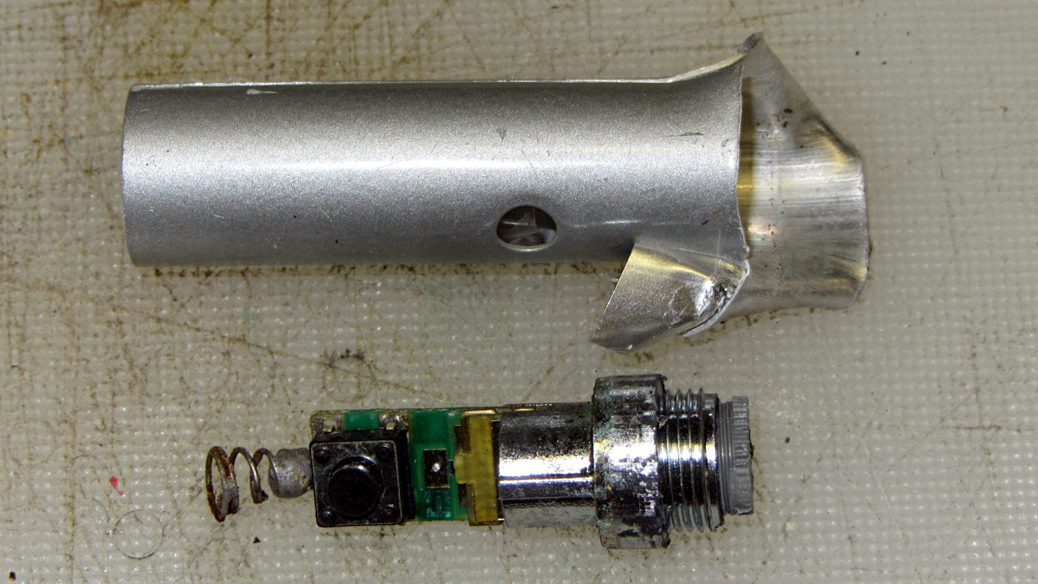
A small and defunct laser pointer emerged from the back of the workbench. There being no way to repair the thing, I filed a slit in the soft aluminum case and peeled it back to extract the guts:
Gutted laser pointer
The corrosion on the spring adequately explains the “defunct” situation; that’s the – terminal for a trio of LR44 watch batteries. The + terminal is the glossy (aluminum flashed?) molded shape with the threads, which friction-jams into the outer tube with a tiny spur for “good” contact.
Hotwiring a power supply to the appropriate terminals shows that the laser still works fine, even if the contacts are shot.
The ribbed gray plastic ring on the business end of the laser adjusts a focusing lens. Behind that lies a cylindrical lens that corrects the beam’s astigmatism. It was a nice pointer, back in the day … and might work its way into an art project, if I ever get finished with the practical stuff.
Here’s what happened when I shut down comments on posts older than a few days:
Softsolder Daily Spam Catch – 2014-04 to 2014-06
Apparently the spammers’ scripts can’t keep up with a short window and most comments happen in a few days, so this seems like a workable compromise. I know for a fact that spammers also employ humans to type comments, but that model doesn’t scale well at all.
Akismet disposes of most spam automatically, but presents me with a list of comments that it can’t classify. That list amounts to 10% of the daily catch, meaning I had to process that much junk every day just to keep up. I don’t know why Akismet can’t classify total gibberish as obvious spam and automatically delete it, but that’s how Akismet works.
As mentioned in the sidebar, send me a note to comment on an older post.
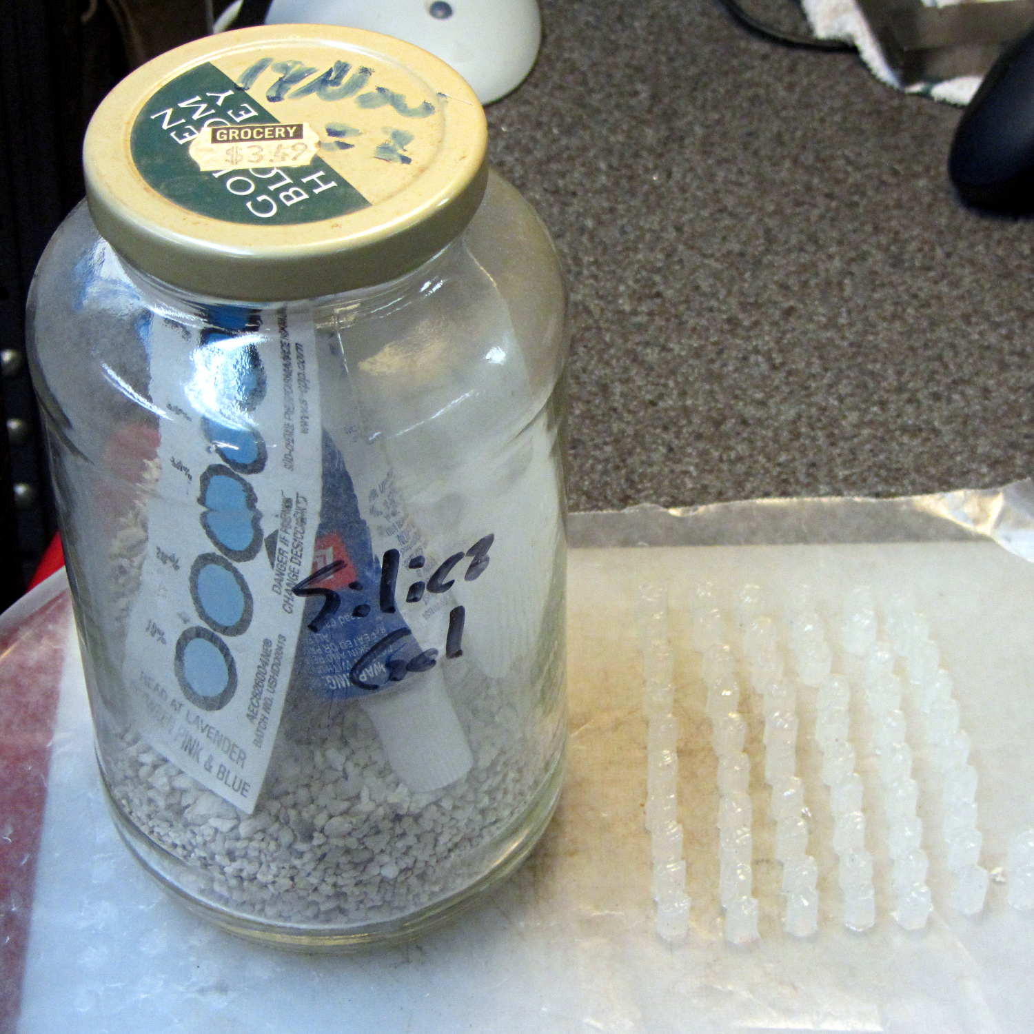
After doing the second batch of quilting pin caps, I dropped the newly opened silicone caulk tube into a jar with some desiccant, which worked wonderfully well. Unlike the usual situation where the caulk under the cap hardens into a plug after a few weeks, the tube emerged in perfect condition. In fact, even the caulk in the middle of the conical nozzle was in good shape, with just a small cured plug on either end; it had been sitting inside a cloth wrap with no sealing at all.
Here’s what it looked like after finishing the last of the most recent caps:
Silicone caulk tube with silica gel
The indicator card says the humidity remains under 10%, low enough to keep the caulk happy and uncured. Well worth the nuisance of having a big jar on the top shelf instead of a little tube next to the epoxy.
Although I thought the desiccant was silica gel, it’s most likely one of the clay or calcium desiccants.
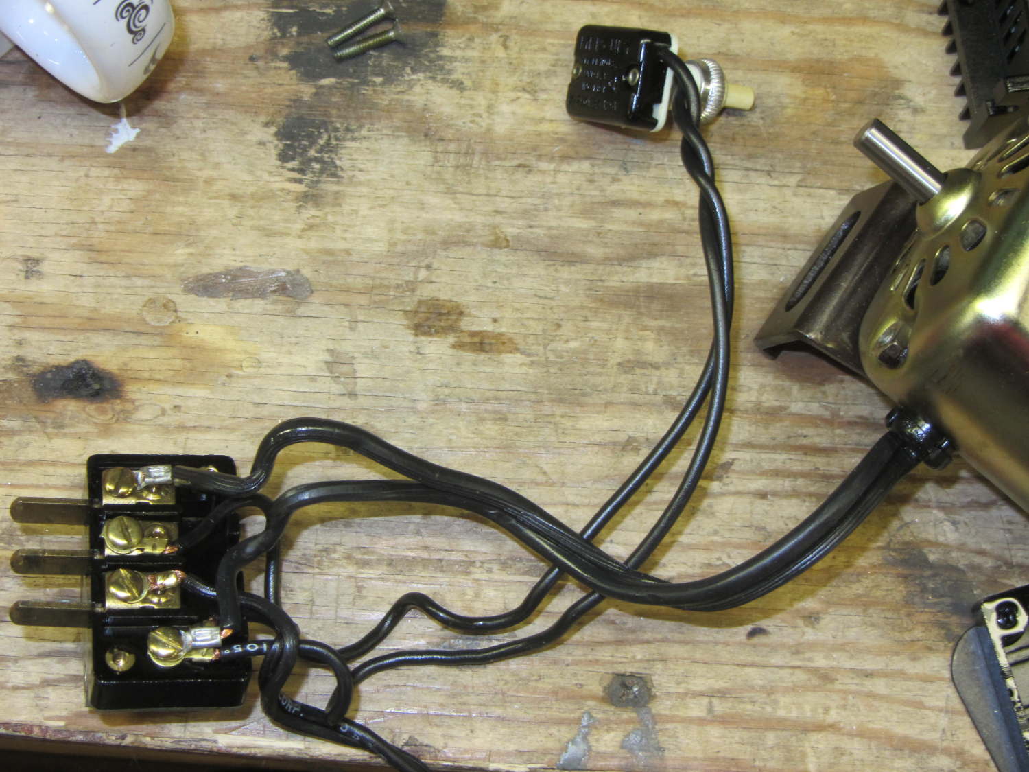
For completeness, the matching socket (not shown) joins two cords:
AC line cord (two wire, not polarized, no ground)
Foot pedal
Extract the motor wiring from that block and connect it to a 50 V / 3 A bench supply, with the positive lead to the marked wire conductor:
Kenmore 158 AC motor – DC power
Cranking the voltage upward from zero:
Kenmore Model 158 AC Motor on DC – RPM vs V
So that’s about 200 RPM/V, offset by 2800 RPM. Totally unloaded, of course.
The original data:
DC V
DC A
RPM
Notes
15
0.29
690
Barely turning
20
0.28
1380
Finger-stoppable
25
0.29
2350
30
0.29
3450
35
0.30
4450
40
0.29
5740
45
0.29
6780
Still finger-holdable at start
50
0.29
8000
I can hold the shaft stopped between my fingers up through 45 V, with 0.54 A locked-rotor current at 25 V. The motor doesn’t have a lot of torque, although it’s operating at less than half the normal RMS voltage.
I should take those numbers with the motor driving the sewing machine to get an idea of the actual current under a more-or-less normal load.
Reversing the power supply leads shows that the motor rotates only counterclockwise, which is exactly what you’d expect: both polarities of the normal AC sine wave must turn the motor in the same direction.