Ed Nisley's Blog: Shop notes, electronics, firmware, machinery, 3D printing, laser cuttery, and curiosities. Contents: 100% human thinking, 0% AI slop.
Fancy new sewing machines can stop with the needle either up (so you can remove the fabric) or down (to nail it in place while you rotate it). This requires sensing the needle position, which prompted me to spend far too long contemplating all the mechanical gadgetry driven by the motor.
As nearly as I can tell, the crank counterweight behind the handwheel produces the most unambiguous position reports. Here’s what it looks like with the needle down:
Kenmore 158 – main shaft counterweight
As you’d expect, with the shaft rotated exactly 180° from that point, the needle is up.
The inviting space just above the shaft provides room for the bobbin winder that engages a knurled ring on the back of the handwheel, but the lower space seems to be available. The counterweight sits about halfway into the back of the handwheel, so the sensors must look at the frame side of the counterweight.
Two adjacent sensors could detect the edge of the counterweight, which would be enough to uniquely identify both positions. If they were spaced across the lower-left edge in that picture:
01 = trailing edge = bottom dead center = needle down (as shown)
00 = open air = needle rising
10 = leading edge = top dead center = needle up
11 = solid steel = needle falling
Either sensor gives you one pulse per handwheel revolution and the combination gives you a quadrature output of both position and direction. The top speed of 1000 RPM produces 17 Hz square waves.
An additional pulse/rev sensor on the motor shaft would give better control over the motor speed, as the handwheel runs at 1/10 the motor speed with belt slip built right in. Figure 10 kRPM → 170 Hz pulses.
From a cold start, you know the shaft angle to within a bit under 180°. If the motor can turn in both directions (as would a stepper or DC motor), you can always move the needle upward. If it turns only forward (as does the AC motor) and the needle is falling, then you probably don’t want to move the motor until you get a button push indicating that all fingers are clear.
A pair of Hall effect sensors might suffice to detect that big hunk of steel, perhaps with a pair of teeny magnets glued to the face or a magnetic circuit closed by the counterweight.
Huh. Who’d’a thunk it? That’s just too good to pass up…
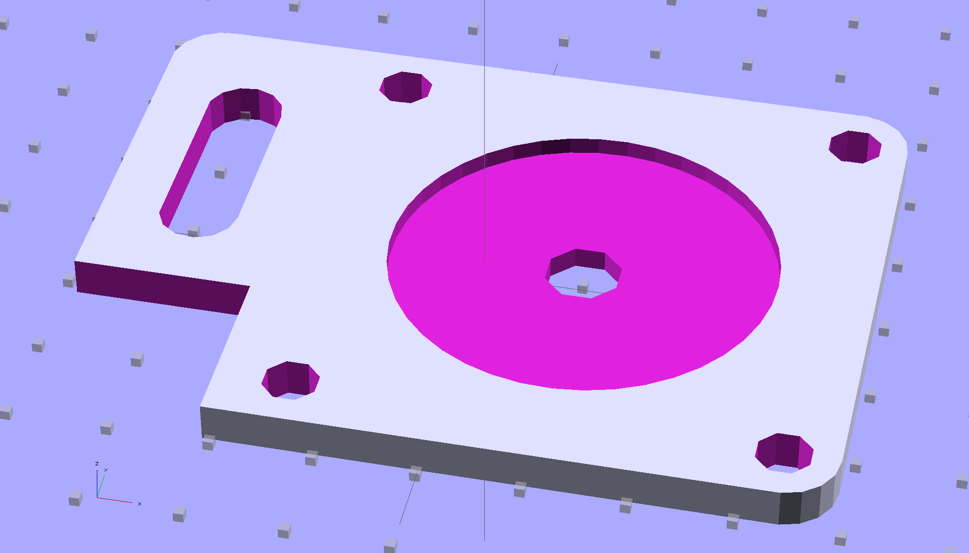
Although you wouldn’t use PLA for the real motor mount, this was easy:
Drive Motor Mount – solid model
And the whole affair fits pretty much like you’d expect:
Kenmore 158 – NEMA 23 stepper – on adapter
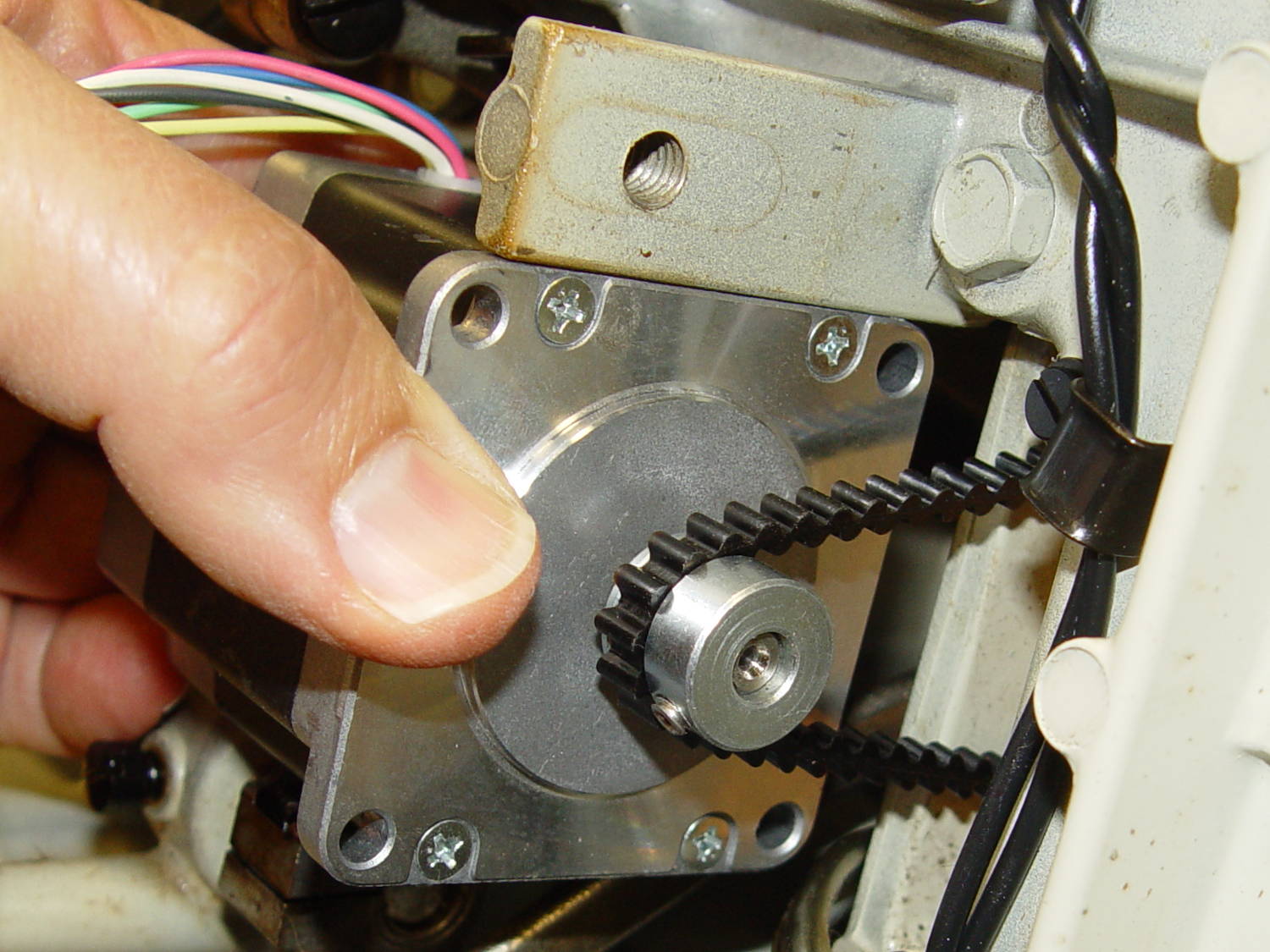
The NEMA 23 motor doesn’t have the same end profile as the AC motor and the adapter plate gets in the way of the pulley, but flipping the pulley end-for-end perfectly aligned the belt.
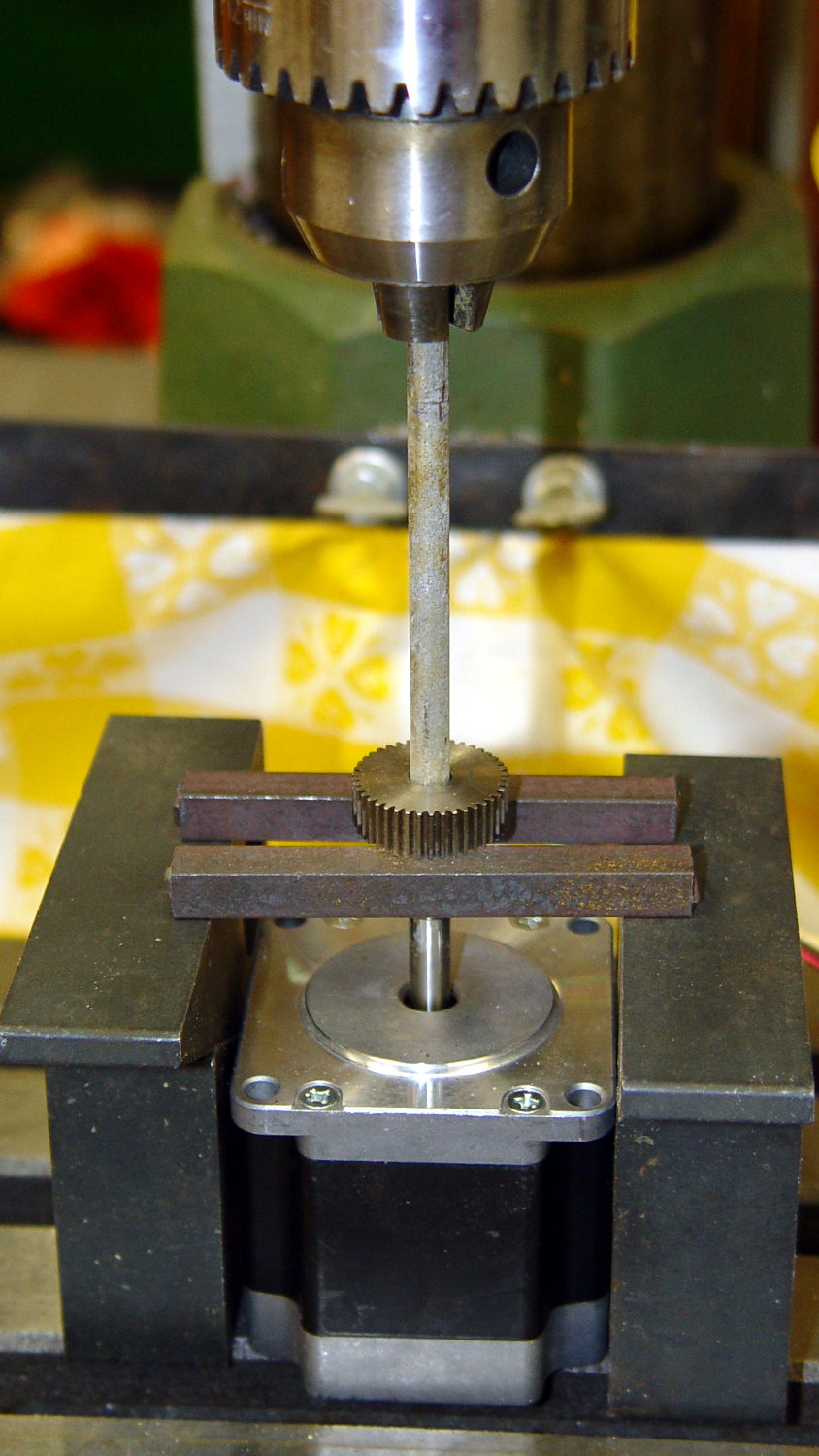
For whatever it’s worth, here’s how I removed the pressed-on gear from the shaft:
NEMA 23 Stepper – removing gear
I’m pretty sure I have a little gear puller somewhere, but it’s not where I expected to find it, which means it could be anywhere.
Much to my astonishment, the shafts on both motors are exactly 1/4″ inch. I filed a flat on the shaft to avoid having the setscrew goober the poor thing.
A stepper isn’t the right hammer for this job, because it can’t possibly reach 8000 rpm, but it’ll be good enough to explore the parameter space and weed out the truly stupid mistakes. A brushless DC motor from halfway around the planet would fit in the same spot.
The OpenSCAD source code:
// NEMA 23 Stepper Mounting Plate
// Ed Nisley - KE4ZNU - June 2014

Layout = "Build";			// Build Show

//- Extrusion parameters must match reality!
//  Print with 4 shells and 3 solid layers

ThreadThick = 0.20;
ThreadWidth = 0.40;

HoleWindage = 0.2;			// extra clearance

Protrusion = 0.1;			// make holes end cleanly

AlignPinOD = 1.70;			// assembly alignment pins: filament dia

inch = 25.4;

function IntegerMultiple(Size,Unit) = Unit * ceil(Size / Unit);

//----------------------
// Dimensions
// Origin at bottom front corner of plate as mounted on machine
//	motor mounted on rear surface, so recess is on that side

PlateThick = 4.0;				// overall plate thickness

SlotOffset = [10.0,13.0,0];		// center nearest origin, motor in X+,Y+ direction
SlotSize = [8.0,25.0];			// diameter of mounting screw , overall end-to-end length

CutoutOffset = [0.0,40.0,0];	// cutout around machine casting
CutoutSize = [18.0,18.0];

MotorBase = 58.0;				// square base plate side
MotorHoleOC = 47.2;				// hole center-to-center spacing
MotorHoleOffset = MotorHoleOC/2;
MotorHoleDia = 5.0;
MotorBaseCornerRadius = (MotorBase - MotorHoleOC)/2;

FlangeWidth = 20.0;				// mounting flange

MotorCenter = [(FlangeWidth + MotorBase/2),(MotorBase/2),0];		// XY of shaft centerline

MotorShaftDia = 7.0;			// allow some clearance

HubDia = 38.5;					// allow some clearance
HubHeight = 1.8;

//----------------------
// Useful routines

module PolyCyl(Dia,Height,ForceSides=0) {			// based on nophead's polyholes

  Sides = (ForceSides != 0) ? ForceSides : (ceil(Dia) + 2);

  FixDia = Dia / cos(180/Sides);

  cylinder(r=(FixDia + HoleWindage)/2,
           h=Height,
           $fn=Sides);
}

module ShowPegGrid(Space = 10.0,Size = 1.0) {

  RangeX = floor(100 / Space);
  RangeY = floor(125 / Space);

	for (x=[-RangeX:RangeX])
	  for (y=[-RangeY:RangeY])
		translate([x*Space,y*Space,Size/2])
		  %cube(Size,center=true);

}

//----------------------
// Build it!

module BasePlate() {

	difference() {
//		cube([(MotorCenter[0] + MotorBase/2),MotorBase,PlateThick],center=false);
		linear_extrude(height = PlateThick) {
			hull() {
				translate([MotorBaseCornerRadius,MotorBaseCornerRadius])
					circle(r=MotorBaseCornerRadius);
				translate([MotorBaseCornerRadius,MotorBase - MotorBaseCornerRadius])
					circle(r=MotorBaseCornerRadius);
				translate([FlangeWidth + MotorBase - MotorBaseCornerRadius,MotorBase - MotorBaseCornerRadius])
					circle(r=MotorBaseCornerRadius);
				translate([FlangeWidth + MotorBase - MotorBaseCornerRadius,MotorBaseCornerRadius])
					circle(r=MotorBaseCornerRadius);
			}
		}

		translate(MotorCenter - [0,0,Protrusion]) {
			rotate(180/8)
				PolyCyl(MotorShaftDia,(PlateThick + 2*Protrusion),8);		// shaft hole
			PolyCyl(HubDia,(HubHeight + Protrusion));						// hub recess
			for (x=[-1,1] , y=[-1,1]) {
				translate([x*MotorHoleOffset,y*MotorHoleOffset,0])
					rotate(180/8)
						PolyCyl(MotorHoleDia,(PlateThick + 2*Protrusion),8);
			}
		}

		translate(SlotOffset - [0,0,Protrusion]) {							// adjustment slot
			linear_extrude(height = (PlateThick + 2*Protrusion))
				hull() {
					circle(d=SlotSize[0]);
					translate([0,(SlotSize[1] - SlotSize[0])])
						circle(d=SlotSize[0]);

				}
		}

		translate(CutoutOffset - [Protrusion,0,Protrusion])
			linear_extrude(height = (PlateThick + 2*Protrusion))
				square(CutoutSize + [Protrusion,Protrusion]);
	}
}

ShowPegGrid();

if (Layout == "Show") {
	BasePlate();
}

if (Layout == "Build") {
	translate([-(SlotOffset[0] + MotorBase/2),MotorBase/2,PlateThick])
		rotate([180,0,0])
			BasePlate();
}
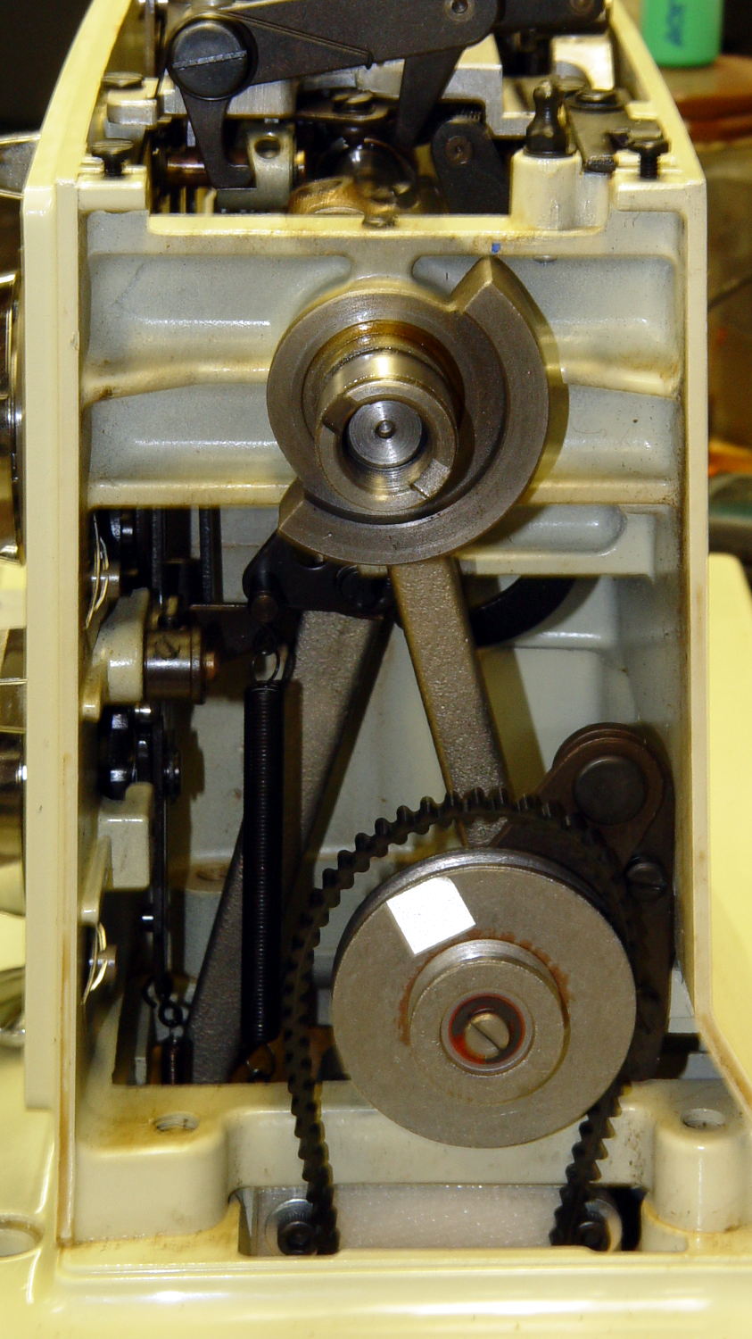
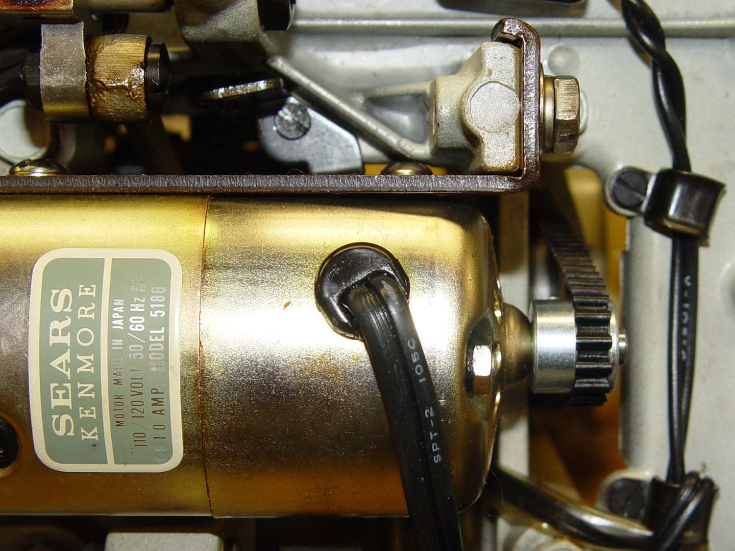
The Kenmore Model 158 sewing machine contains a 120 VAC / 1 A motor that powers all the moving parts through a V belt:
Kenmore 158 – AC drive motor – overview
Looking up through the body:
Kenmore 158 – AC motor and belt – bottom
A double pulley on a jackshaft reduces the motor speed on the way to the handwheel:
Kenmore 158 – handwheel – jackshaft pulley
The motor and handwheel turn counterclockwise in normal operation, but can be turned clockwise by hand as needed. The belt tension isn’t very high and the jackshaft pulleys can slip, but I’m not sure if that’s intentional or the result of several decades of runtime.
Despite the cogged belt, the pulleys are smooth; it’s not a positive-drive transmission with timing-belt pulleys.
You could, if you had to, run a belt from the handwheel directly to the motor, although the pulley would ride about 7 mm further out on the shaft. I have no way to measure the lengths with any confidence in the results; one could calculate the lengths based on pulley diameters and center spacing.
Sticking retroreflective tape on the pulleys and handwheel, then deploying the laser tachometer, provides some minimum and maximum speeds:
Motor: 2100 – 8500 rpm
Jackshaft: 800 – 3200 rpm
Handwheel: 200 – 930 rpm
Those aren’t entirely consistent, because I’m using the old foot pedal speed control with its defunct carbon disks; the low end, in particular, isn’t as slow as it can go.
In any event, there’s about a 10:1 speed reduction from motor to handwheel.
The motor label clearly states that it’s 100-120 V AC, but it has brushes, so it’s actually a universal-wound motor that should run happily on DC.
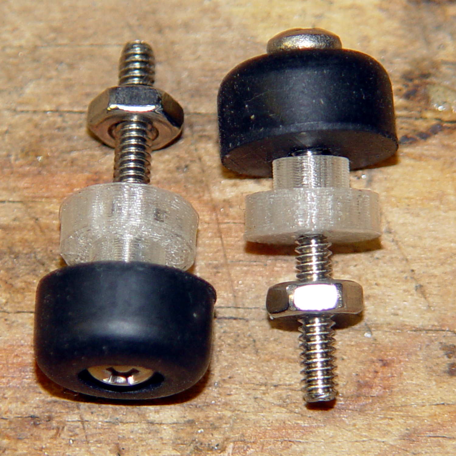
As you’d expect, the soft feet on the bottom of the Kenmore Model 158 sewing machine’s foot pedal control turn into hard buttons after a few decades. The OEM feet have mushroom tops that push through holes in the case and latch in place; of course, none of the rubber feet in my collection match the hole diameter or case thickness.
No problem! Design a bushing that fits the case hole and passes a 4-40 screw:
Speed Control Foot Bushing
Then print up a handful, add screws to fit the rubber feet, and top off with nuts:
Kenmore 158 – pedal foot bushing – detail
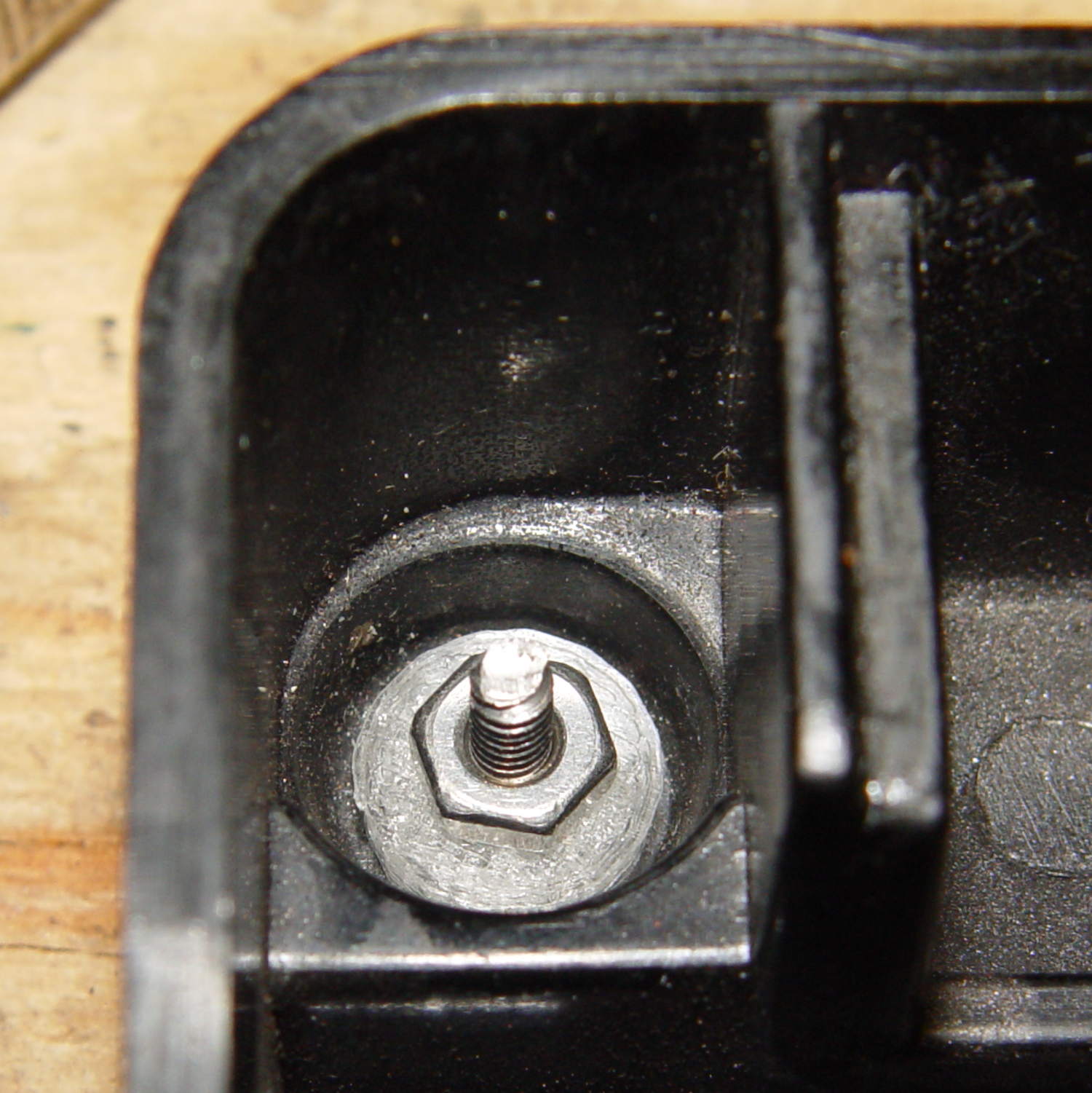
Installed, with the screws cropped to a suitable length, they look about like you’d expect:
Kenmore 158 – pedal foot bushing – interior
Turns out that the springs supporting the foot pedal rest in those pockets, so the bushing reduces the spring travel by a few millimeters. The springs aren’t completely compressed with the pedal fully depressed, so it’s all good.
The OpenSCAD source code:
// Kenmore Model 158 Sewing Machine Foot Control Bushings
// Ed Nisley - KE4ZNU - June 2014

//- Extrusion parameters must match reality!
//  Print with 2 shells and 3 solid layers

ThreadThick = 0.20;
ThreadWidth = 0.40;

HoleWindage = 0.2;			// extra clearance

Protrusion = 0.1;			// make holes end cleanly

function IntegerMultiple(Size,Unit) = Unit * ceil(Size / Unit);

//----------------------
// Dimensions

Stem = [2.5,5.7];			// through the case hole
Cap = [3.0,10.0];			// inside the case

LEN = 0;
DIA = 1;

OAL = Stem[LEN] + Cap[LEN];

ScrewDia = 2.8;				// 4-40 generous clearance

//----------------------
// Useful routines

module PolyCyl(Dia,Height,ForceSides=0) {			// based on nophead's polyholes

  Sides = (ForceSides != 0) ? ForceSides : (ceil(Dia) + 2);

  FixDia = Dia / cos(180/Sides);

  cylinder(r=(FixDia + HoleWindage)/2,
           h=Height,
           $fn=Sides);
}

module ShowPegGrid(Space = 10.0,Size = 1.0) {

  RangeX = floor(100 / Space);
  RangeY = floor(125 / Space);

	for (x=[-RangeX:RangeX])
	  for (y=[-RangeY:RangeY])
		translate([x*Space,y*Space,Size/2])
		  %cube(Size,center=true);

}

//----------------------
// Build it!

ShowPegGrid();

difference() {
	union() {
		cylinder(d=Stem[DIA],h=OAL,$fn=16);
		cylinder(d=Cap[DIA],h=Cap[LEN],$fm=16);
	}
	translate([0,0,-Protrusion])
		PolyCyl(ScrewDia,OAL + 2*Protrusion,6);
}
That’s a fairly large snapping turtle in the middle of the Dutchess Rail Trail, between Morgan Lake and the Violet Avenue tunnel.
Snappers can move just under the speed of light for about a foot in order to latch onto you, but they’re not quite as fast while turning around: always pass to their rear. You do not attempt to save them from their folly at being in the middle of the road / trail / driveway: they have absolutely no patience with meddlers.
Turtles lay eggs around this time of year, which means they’re on the move, which means they cross roads, which means they get mashed. We’ve seen maybe half a dozen smashed turtles on our usual routes.
Quite some years ago, we found one of its relations in the flower garden beside our house, where it climbed at least 18 inches of vertical concrete block to see what was inside. It was about two feet long, jaws to tail, and obviously a survivor:
Snapping Turtle on wall
Those missing plates probably didn’t help its attitude in the least.
It eventually klonked down to the driveway without our assistance:
Snapping Turtle on driveway
After a pause for gimbal unlocking and compass recalibration, it ambled off toward the Mighty Wappingers Creek. The wall gets much shorter to the right, which is likely where it climbed up.
Being that type of guy, I make a local backup of this blog, using the Export function that normally serves to migrate blogs from WordPress.com to a self-hosted WordPress site. WordPress handles the disaster-recovery backup just fine, but cloud-based Internet companies have a tendency to just vanish without too much warning (Everpix and Code Spaces come to mind), so having my blog’s verbiage where I can touch it gives me a warm, fuzzy feeling.
Anyhow, the most recent export failed completely, whereupon I filed a support request:
My irregular backup involves exporting my blog, which has worked up to this evening, and tucking it away. Alas, it dies with the cryptic message This webpage is not found
Clicking More reveals:
No webpage was found for the web address: [... huge URL snipped...]
Error code: ERR_FILE_NOT_FOUND
[… snippage …]
Can you get Export working again?
The response included the usual reboot-that-sucker advice:
[…] If you have problems next time you export your site, try clearing your browser cache and cookies and redoing the export. […]
But shaking the dice never really works:
OK, I’ve done that with three different browsers: Chromium, Firefox, and Pale Moon.
I’ve run Firefox in Safe Mode with all add-ons disabled, flushed everything, and the export function fails the same way.
The file name you gave me does not resemble the file name / URL / whatever presented to my browser.
That suggests the hole is not in this end of the boat.
Which forced a bump to Level 2:
[…] I’ve been discussing this with our developers and it seems the problem is that your export file it too large. We are hoping to fix this so that it won’t be an issue for you in the future but for the time being, you will have to export date-ranged posts. […]
I realise this isn’t ideal but it’s just a temporary workaround until this becomes a working feature in the not-too-distant future. I don’t have a date of completion at this stage.
Translation: “It’s like that and that’s the way it is.” When there’s no “date of completion”, that means the project is not on their calendar, which means they’ll never get around to doing it. A later conversation suggests that maybe August is the target date; we shall see.
So, how big is your blog, Ed?
The most recent backup export XML file weighed in at 28 MB, which doesn’t seem all that large by contemporary standards. Bear in mind that the file doesn’t include any of the 4300 images that occupy just under 1 GB (of the 3 GB one gets without buying a “media upgrade”).
It turns out size doesn’t matter:
It’s not the size of the file that is causing problems but rather the number of posts and media files. There are over 2000 posts and over 4000 media files.
I cannot imagine that those limits are held in 11 or 12 bit binary fields, but that would explain everything.
Apparently, the WordPress designers never expected anybody to produce one post a day, every day since late 2009. I’m certain I’m not the most prolific blogger on wordpress.com, but perhaps I’m the only one who’s ever tried to export the results …
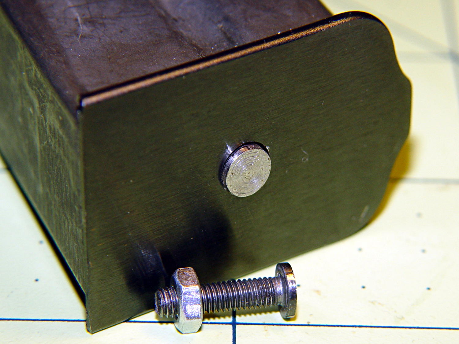
It started as a normal M3x0.5 socket-head cap, but I reduced the diameter and turned off the socket to fit the existing hole in the exterior floor plate:
BHP floor plate screw – disk head
The head was just barely too large for the largest of my pin vises. Drat!
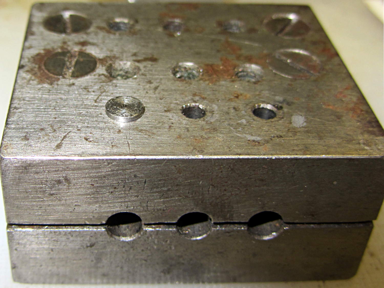
The easiest way (for me, anyhow) to install that screw into the epoxy-loaded block started by dropping it into what seems to be a shim-punching tool:
Base screw in alignment block
It’s in the left hole of the top front row: talk about protective coloration, eh?
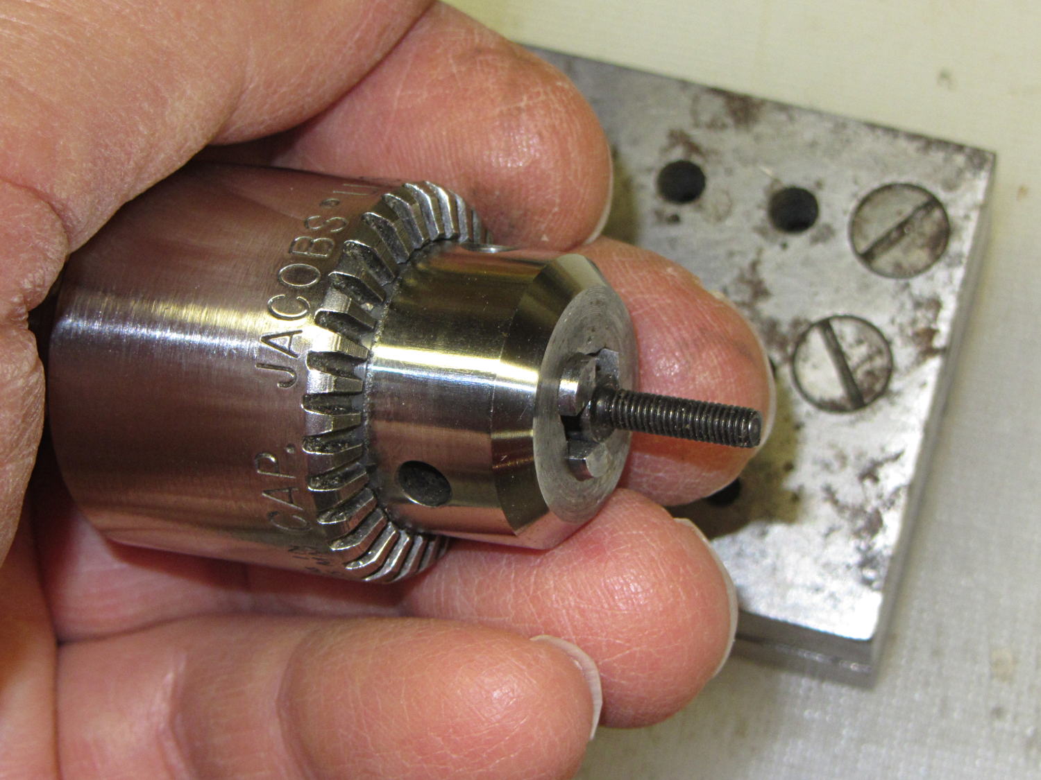
Then capture it in one of the Sherline’s drill chucks:
Base screw in Jacobs chuck
Which makes it trivially easy to turn right into the nut brazed to the floor plate and the epoxy inside the block. When the epoxy cures, the screw, nut, floor plate, spring, and block become one solid unit.
That punch block came with the lathe tooling, made for some special purpose long lost in history. It comes in handy all the time for other jobs, though, so I think it’s still happy.
(*) The pictures are staged recreations; I was cleaning off the bench and unearthed the spare screws.