The Smell of Molten Projects in the Morning

Ed Nisley's Blog: Shop notes, electronics, firmware, machinery, 3D printing, laser cuttery, and curiosities. Contents: 100% human thinking, 0% AI slop.

Author: Ed

  • Current Sensing: Powered Iron Toroid

    Dell built the GX270 I’m repurposing back in 2004, early on in the capacitor plague years, but only one of the system board caps showed signs of leakage:

    Capacitor plague - 2004 Dell Edition
    Capacitor plague – 2004 Dell Edition

    While I was harvesting some of the connectors, it occurred to me that those powdered iron inductors might make good current sensors, as they’re already wound with heavy gauge copper wires.

    I picked an inductor with enough turns and, although slitting didn’t pose much of a problem, the saw did make a mess of the turns adjacent to the cut:

    Powdered iron toroid - slitting
    Powdered iron toroid – slitting

    Iron powder has more magnetic remnance than ferrite, to the extent that iron swarf clogged the gap. After the first pass, I ran the slit toroid through the degausser to shake it clean and see what damage had been done. It looked OK, so I realigned it on the saw blade and continued the mission, with all the dust vanishing into the vacuum cleaner’s snout.

    Removing the damaged sections left 22 turns. For comparison, I converted the 56 turn ferrite toroid into a 25 turn model by paralleling two 25 turn sections:

    Slit toroids - iron - ferrite
    Slit toroids – iron – ferrite

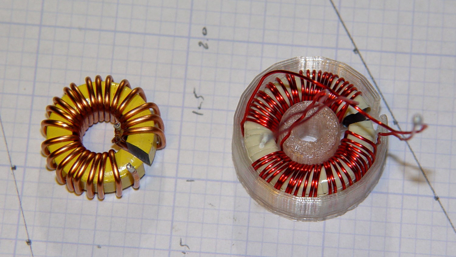
    The enamel wire on the iron toroid measures 40 mil diameter, close enough to 18 AWG.

    Paralleling two 24 AWG windings on the ferrite toroid produces twice the copper area of a single winding, so the resistance is the same as a single 21 AWG winding (3 AWG steps = factor of two area change). That’s three steps smaller than the 18 AWG on the iron toroid, so the resistance is a factor of two larger than the heavier wire.

    The paralleled winding has the advantage of reducing the power dissipation required to produce the same magnetic flux density, without the difficulty of winding heavier wire. That may not actually matter, given the relatively low currents required by the motor in normal operation.

    Wedging a Hall sensor into the gaps and stepping the current produced two useful graphs:

    Iron and ferrite toroids - Hall sensor output
    Iron and ferrite toroids – Hall sensor output

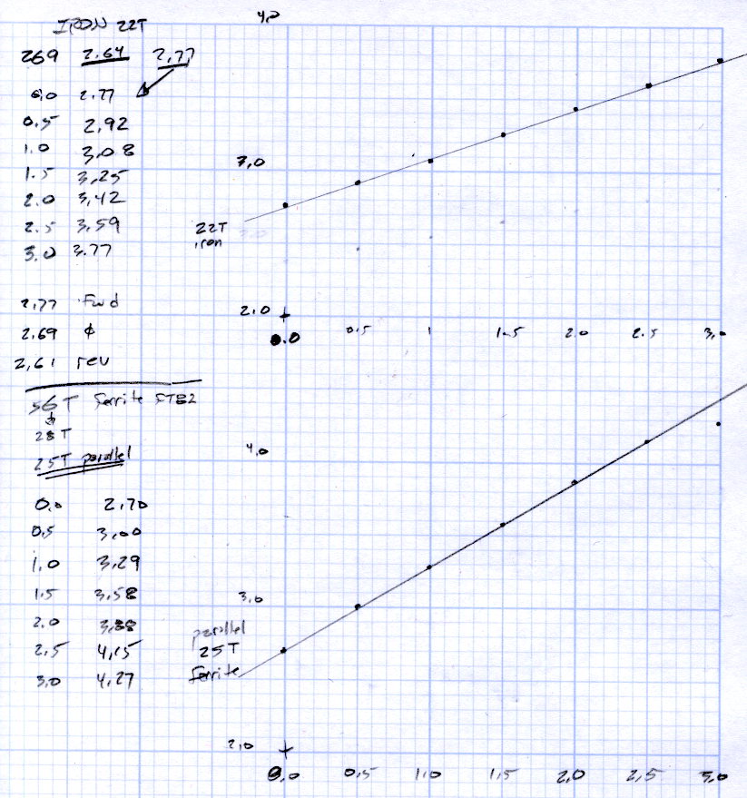
    The iron toroid has lower permittivity (less flux density for a given magnetizing force), which means the full-scale range exceeds 3 A and the useful range up to 1 A covers only 300 mV.

    The last point on the ferrite curve shows the Hall sensor output saturating just over 4 V, with 1.5 V of range.

    The slope, in mV/A

    • Powdered iron: 340
    • Ferrite: 540

    Boosting the slope of the powdered iron by 25/22 gives 386 mV/A, so the iron permeability really is 70% of the ferrite. That’s modulo the gap size, of course, which surely differs by enough to throw out all the significant digits.

    Obviously, an op amp circuit to remove the offset and rescale the output to 0-5 V will be in order.

    The previous graph for the ferrite toroid with the complete 56 turn winding shows, as expected, about twice the output of this 25 turn version:

    FT82-43 - 56 turns - 24 AWG
    FT82-43 – 56 turns – 24 AWG

    The linear part of that line is 1375 mV/A, although I can’t vouch that the data came from the same Hall effect sensor. Scaling it by 25/56 gives 613 mV/A, suggesting it’s not the same sensor.

    Having developed an emotional attachment to the ferrite toroid, I’ll use it in the first pass of the current feedback circuit. If the motor need a bit less sensitivity or lower resistance, the powdered iron toroid looks like a winner.

    Memo to self: Always degauss iron toroids before slitting!

  • FC1002 Frequency Counter Faceplate: BLAM!

    So I picked up the frequency counter and found this:

    FC1002 Frequency Counter - split shattered faceplate
    FC1002 Frequency Counter – split shattered faceplate

    The outer, previously cracked pieces of the faceplate split parallel to the front panel, separating into two layers, and popped free of their mount. The layer closest to the panel remains intact.

    The fragments were flexible and the bottom layer was rigid, suggesting the faceplate consisted of two parts, perhaps an acrylic (?) base with a soft silicone (?) poured atop it for armor and scratch protection.

    It still works fine and the acrylic (?) layer will suffice for my simple needs, despite being slightly marred by the cyanoacrylate glue I slobbered into the cracks.

    I definitely didn’t see that coming…

  • Extracting Video Frames and Overlaying Text

    The avconv incantation required to put text on frames extracted from a video file looks like this (it’s all on one line, so you’ll need some side scrolling action):

    avconv -ss 00:11:47 -i /mnt/backup/Video/2014-09-08/MAH00070.MP4 -t 1 -f image2 -q 1 -vf "drawtext=fontfile=/usr/share/fonts/truetype/ttf-dejavu/DejaVuSansMono.ttf : text='2014-09-08 10\:58\:47' : fontcolor=white : fontsize=60 : box=1 : boxcolor=black@0.7 : x=1200 : y=30" MAH00070-001147-%03d.jpg
    

    That’s applying some hints to the rather succinct drawtext doc.

    The -ss 00:11:47 sets the starting time relative to the beginning of the file, so it’s an offset that, when added to the file start time in the Exif metadata, produces the actual time-of-day. The extracted frames begin at the closest “seek point”, which I presume will be pretty close to the specified second. The -accurate_seek option may be relevant. Verifying all that could be tricky.

    The -t 1 specifies the duration. Each second produces 60 frames, numbered from 001 to 060 in the output filename, as defined by the %03d in the output filename format string.

    The -vf "drawtext=" gibberish does the actual text overlay, with all the parameters tucked inside the double quotes.

    You must escape all colons in the text string (as '10\:58\:47', note the single quotes), because unescaped colons separate the drawtext options.

    The fontsize seems to be in pixels with an upper limit of 72.

    The boxcolor rectangle just barely covers the characters; there’s no way to enlarge it just a few more pixels to make a nice frame. The fraction at the end of black@0.7 string produces 70% opacity.

    I manually added the actual starting time (10:47) to the offset time for each segment (previewed with vlc), jammed that into the avconv command, and extracted some interesting frames from a recent ride…

    I get plenty of clearance while approaching an intersection, which is pleasant:

    MAH00070-001118-047
    MAH00070-001118-047

    Absorbed in something on the passenger seat while I’m trackstanding the ‘bent and watching the brake lights:

    MAH00070-001139-017
    MAH00070-001139-017

    The turn signal goes on just after acceleration commences:

    MAH00070-001141-017
    MAH00070-001141-017

    Because I never pass on the right, I didn’t participate in a classic right hook:

    MAH00070-001144-050
    MAH00070-001144-050

    The traffic signal goes yellow as I cross the walk ladder, with the tail of the SUV visible beyond the crosswalk on the right. The green-to-yellow transition takes 10 frames = 1/6 second and this image shows the half-intensity point of both incandescent bulbs:

    MAH00070-001147-041
    MAH00070-001147-041

    The rest of the ride seemed less eventful.

    Frankly, that’s way too much handwork for the results in the upper-right corner. I think a better way starts with extracting unannotated frames from the video, then slapping timestamps on them using ImageMagick, calculating and feeding it the appropriate values for each frame.

    Putting the annotation up in the sky seems better than near the bottom corners, if only because images of the pavement might actually be useful. The timestamp needs the frame number and I think splitting it into two shorter sections (date and time) in the left and right upper corners might work better.

  • Monthly Image: Hummingbird!

    Mary grows Scarlet Runner Beans with vivid red flowers specifically for the Ruby Throated hummingbirds that frequent the back yard:

    Hummingbird with Scarlet Runner Bean flowers
    Hummingbird with Scarlet Runner Bean flowers

    This female perched quite a while on that tendril while sticking her tongue out; it looks like a length of monofilament fishing line. The male also feeds on those flowers, although I’ve never seen him perch anywhere for more than a few seconds.

    We wish them success in raising their chicks!

    Hand-held with the Canon SX-230HS zoomed all the way in, then ruthlessly cropped.

  • StaticCider Sighting

    We took a river cruise from Hudson NY on the first day of the Cycling the Hudson Valley ride and, being that type of guy, I spotted this redecorated rail car on the east shore of the Hudson River:

    StaticCider railcar tag sighting - Hudson NY
    StaticCider railcar tag sighting – Hudson NY

    Feeding the obvious search term into the obvious search engine produced two other sightings in Minnesota during 2011. Puts one in mind of Where’s George

    Mad props: unlike most taggers, he / she painted around the car number and ID patterns.

  • Cellular Toad II

    It seems toads really like the plant cell packs that Mary uses to start her garden veggies:

    Cellular Toad - in cell pack
    Cellular Toad – in cell pack

    The garden isn’t quite as snug, but the camouflage works much better:

    Cellular Toad - in garden
    Cellular Toad – in garden

    It’s been a dry year and we haven’t seen many toads or slugs around the house.

  • Dell Optiplex GX270 Power Control PCB Connections

    The general idea is to gut an old Dell Optiplex GX270 and stuff the high-voltage parts of the sewing machine controller inside a well constructed and solidly grounded metal shield inside a not-too-ugly plastic box. It’d be nice to reuse the power control button and status LEDs on the front panel…

    The few parts on the front of the through-hole board:

    Dell Power Button PCB - component
    Dell Power Button PCB – component

    The copper side, with annotations:

    Dell Power Button PCB - copper
    Dell Power Button PCB – copper

    The red tracer on the ribbon cable goes to Pin 1, which is a blind key on the PCB.

    The LEDs do not have ballast resistors, so those must go on a circuit board somewhere else.

    The connections:

    16 14 12 10 8 6 4 2
    Gnd nc nc nc nc HD+ HD- Button+
    Gnd nc Gnd Pwr Y+ Gnd Pwr G+ Gnd Key
    15 13 11 9 7 5 3 1