Ed Nisley's Blog: Shop notes, electronics, firmware, machinery, 3D printing, laser cuttery, and curiosities. Contents: 100% human thinking, 0% AI slop.
In these degenerate times, it seems anyone can just buy a crysknife:
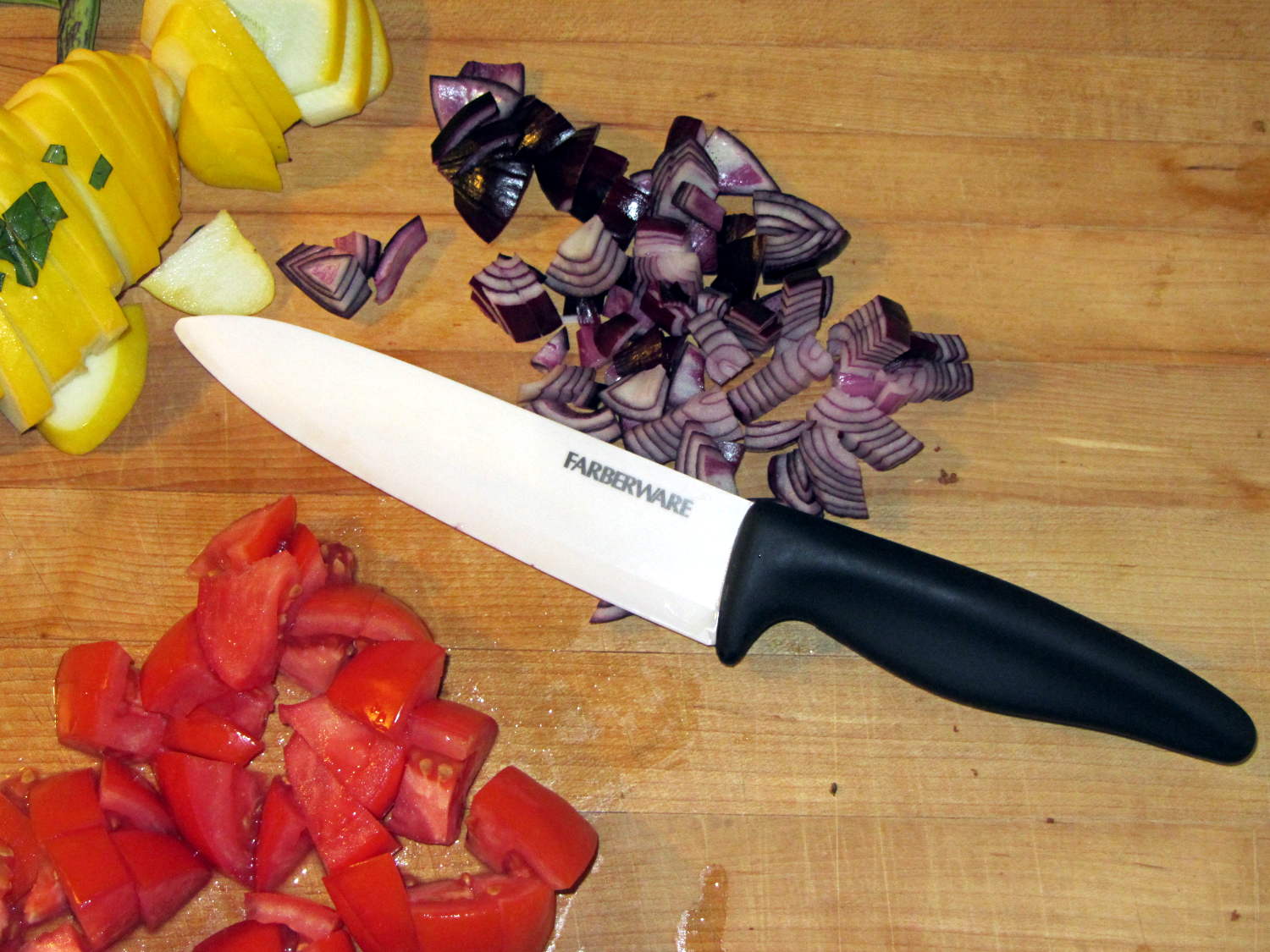
Farberware ceramic knife
Admittedly, it lacks the original’s kinjal shape and curved blade. We once had a double-edged, serrated kitchen knife and I swore a mighty oath on the bones of my ancestors to never, ever make that mistake again.
Surprisingly, the plastic handle balances well with the ceramic blade: no need for another tungsten counterweight. The handle extends slightly below the blade’s heel, which may call for some abrasive adjustment.
The blade is slightly thicker than the wonderful steel santokuknives we’ve been using forever and doesn’t taper uniformly from spine to edge, so it’s no good for constrained cutting (like quartering an apple). The hollow-ground section behind the edge forms a wedge that cracks apples apart, unlike the santoku’s full-width taper that just slides right through.
I was mildly surprised to find that it’s no sharper (perhaps that’s “no more keen”) than our steel knives, but, then, I’m wicked with the sharpening steel. The edge arrived minus a few tiny chips and I suspect we’ll add more in normal use, right up to the moment when one of us drops it on the floor.
A gotcha: that blade’s eyeblink affordance is harmless plastic. I must remind myself it’s a real knife with a lethally sharp edge.
Thus far, we’ve sheathed the blade unblooded, in clear violation of the Fremen ritual. May it ever be so…
Given the fragility of ferrite toroids in general and slit toroids in particular, a touch of up-armoring seems sensible:
FT82-43 toroid – mounted
The solid model includes a toroid shell with roughly the right curves:
Toroid Mount – Show layout
That puts a nice rounded shape on the bottom of the armor, not that that makes much difference:
Toroid Mount – Build layout
The central hole passes a 4-40 brass, nylon, or stainless steel screw. Most of the magnetic field stays within the ferrite and, heck, this isn’t a crazy-sensitive analog application, so even an ordinary steel screw shouldn’t cause any particular problems.
The rectangular (not pie-wedge) slit barely passes the Hall effect sensor.
I’ll pour some clear epoxy over the toroid, with tape masking the ferrite core and sealing the ends, to immobilize the windings. That sounds like a good idea after calibration and suchlike.
The OpenSCAD source code, which should be sufficiently parametric that I can crank ’em out for all the other toroids large enough to accept a screw:
// Toroid coil mounting bracket
// Ed Nisley - KE4ZNU - August 2014

Layout = "Mount";			// Coil Mount Build Show

//- Extrusion parameters must match reality!
//  Print with 4 shells and 3 solid layers

ThreadThick = 0.20;
ThreadWidth = 0.40;

HoleWindage = 0.2;			// extra clearance

Protrusion = 0.1;			// make holes end cleanly

AlignPinOD = 1.70;			// assembly alignment pins: filament dia

function IntegerMultiple(Size,Unit) = Unit * ceil(Size / Unit);

//----------------------
// Dimensions

ID = 0;												// subscripts for cylindrical objects
OD = 1;
LEN = 2;

Coil = [10.25,23.50,8.3];							// wound toroid core

SensorThick = 2.0;

BaseThick = IntegerMultiple(1.0,ThreadThick);		// baseplate under coil
WallThick = IntegerMultiple(1.0,ThreadWidth);		// walls beside coil

ScrewHoleDia = 4.0;									// allow alignment slop around 3 mm / #4 screws

//----------------------
// Useful routines

module PolyCyl(Dia,Height,ForceSides=0) {			// based on nophead's polyholes

  Sides = (ForceSides != 0) ? ForceSides : (ceil(Dia) + 2);

  FixDia = Dia / cos(180/Sides);

  cylinder(r=(FixDia + HoleWindage)/2,
           h=Height,
           $fn=Sides);
}

module ShowPegGrid(Space = 10.0,Size = 1.0) {

  RangeX = floor(100 / Space);
  RangeY = floor(125 / Space);

	for (x=[-RangeX:RangeX])
	  for (y=[-RangeY:RangeY])
		translate([x*Space,y*Space,Size/2])
		  %cube(Size,center=true);

}

//----------------------
// Basic coil shape

module CoilShape() {

CornerRadius = min((Coil[LEN] / 2),((Coil[OD] - Coil[ID]) / 2))  / 3;
MidRadius = (Coil[ID] + Coil[OD]) / 4;
HalfX = (Coil[OD] - Coil[ID]) / 4 - CornerRadius;
HalfY = (Coil[LEN] / 2) - CornerRadius;

echo(CornerRadius,MidRadius,HalfX,HalfY);

	color("Goldenrod")
	render(convexity = 2)
		rotate(180/20)
			rotate_extrude(convexity=3,$fn=20)
				translate([MidRadius,0])
					hull()
						for (i=[-1,1],j=[-1,1])
							translate([i*HalfX,j*HalfY])
								circle(r=CornerRadius,$fn=24);
}

//----------------------
// Mount

module Mount() {

	difference() {
		rotate(180/20)
			cylinder(h=(BaseThick + Coil[LEN]),d=(Coil[OD] + 2*WallThick),$fn=20);

		translate([0,0,-Coil[LEN]])							// make screw hole
			rotate(180/6)
				PolyCyl(ScrewHoleDia,3*Coil[LEN],$fn=6);

		translate([0,0,BaseThick + Coil[LEN]/2])			// set bottom curve
			CoilShape();

		translate([0,0,BaseThick + Coil[LEN]])				// clear out top
			CoilShape();

		translate([(Coil[ID]/2 + Coil[OD]/2),0,0])
			cube([Coil[OD],SensorThick,3*Coil[LEN]],center=true);
	}
}


ShowPegGrid();

if (Layout == "Coil") {
	CoilShape();
}

if (Layout == "Mount")
	Mount();

if (Layout == "Show") {
	Mount();
	translate([0,0,(BaseThick + Coil[LEN]/2)])
		CoilShape();
}


if (Layout == "Build") {
	Mount();
}
I’m pretty sure that chip at 1 o’clock happened while it was clamped in the vise between two cardboard sheets, but I haven’t a clue as how it got that much force. In any event, that shouldn’t affect the results very much, right up until it snaps in two.
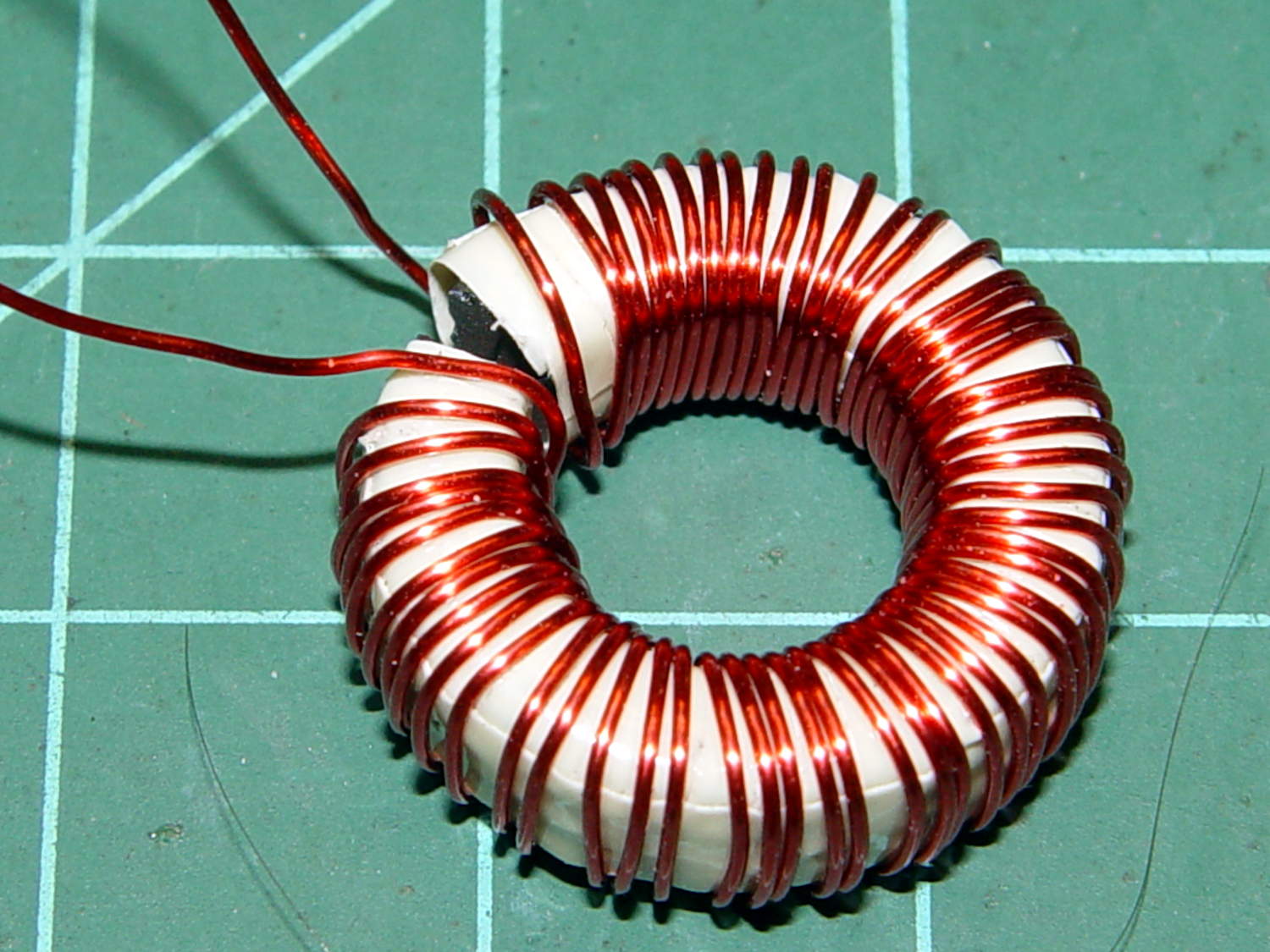
Although the current will come from a (rectified) 120 VAC source, the winding will support only as much voltage as comes from the IR drop and inductive reactance, which shouldn’t be more than a fraction of a volt. Nevertheless, I wound the core with transformer tape:
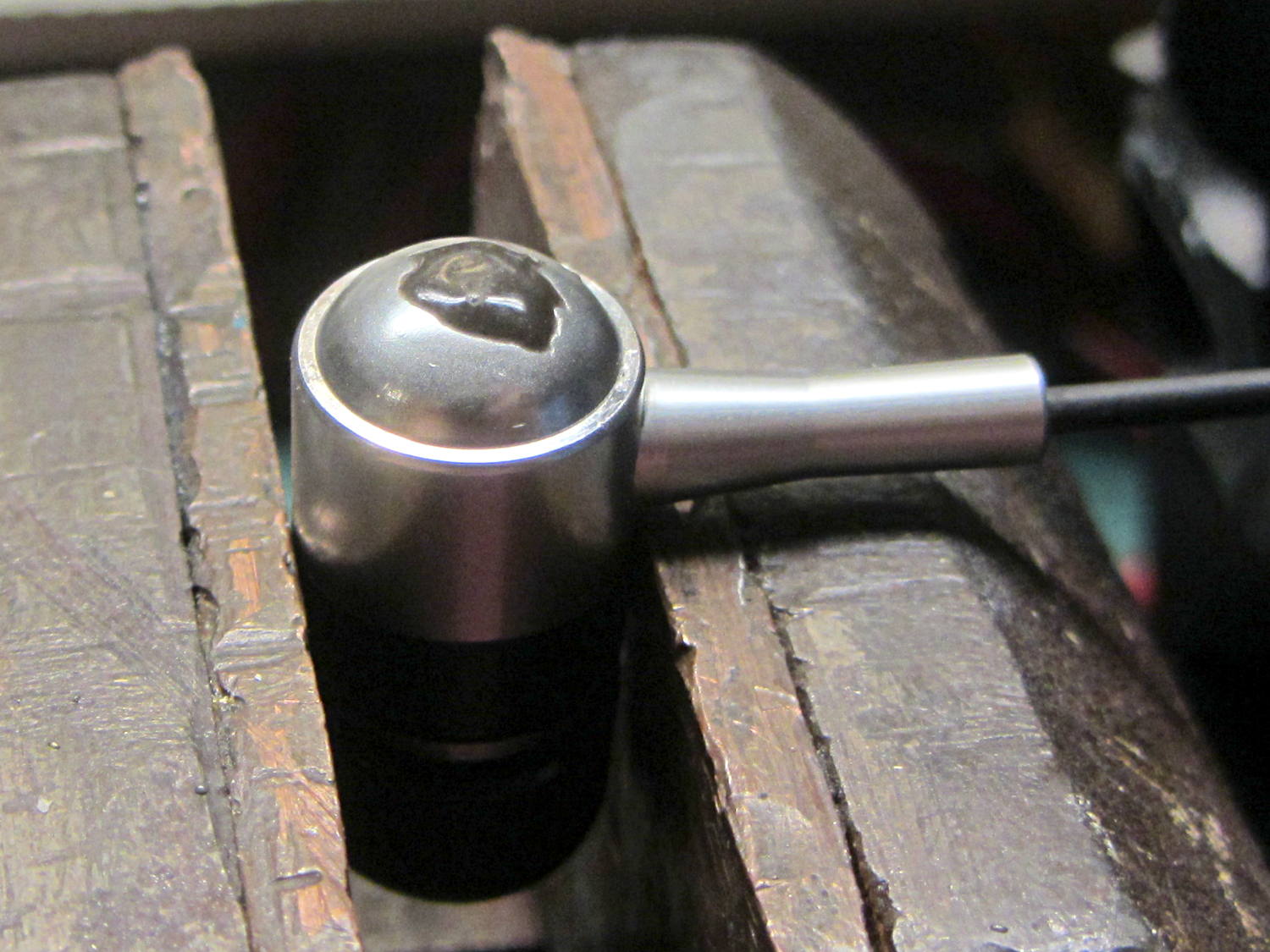
FT82-43 toroid – wrapped
That’s 3M 4161-11 electrical tape (apparently out of production, but perhaps equivalent to 3M’s Super 10 tape) cut into half-foot lengths, slit to 100 mils, and wrapped ever so gently.
The thickest offering from the Big Box o’ Specialty Wire was 24 AWG, so that’s what I wound on it:
FT82-43 toroid – wound
That’s 56 turns, which should convert 2.2 A into 1000 G (enough to max out the Hall effect sensor) and is more in keeping with 24 AWG wire’s 3.5 A current rating.
The insulated core requires just under 1 inch/turn, so figure the length at 56 inch. The wire tables show 26.2 Ω/1000 ft, so the DC winding resistance should be 120 mΩ. My desk meter has 0.1 Ω resolution, which is exactly the difference between shorted probes and probes across the coil: close enough.
The inductance is 170 µH, so the inductive reactance at 120 Hz = 128 mΩ.
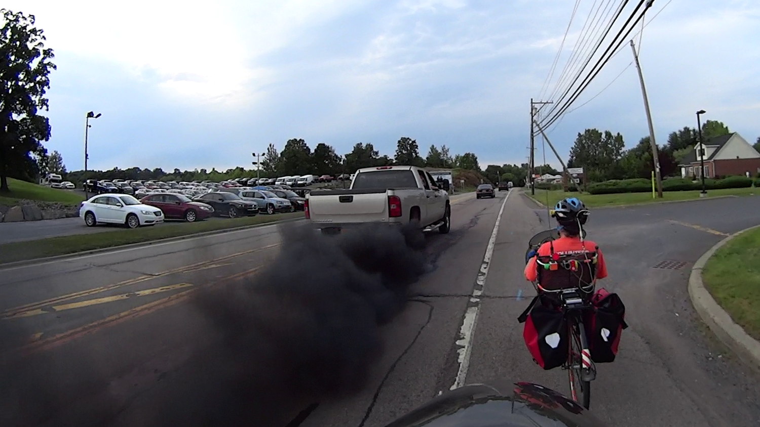
He could claim to be accelerating after a stop signal and that’s just how those big Chevy “clean diesel” engines work, even with DEF and DPF in full effect.
In point of fact, this was deliberate:
Large Pickup – Small Brain – Penumbra
I wish no ill on any man, but, should the Fates decree that a big pickup must be found wrapped around a tree, I have a recommendation.
We were northbound on 9W, returning home after an end-of-summer party.
We rode north to the start of the Cycling the Hudson Valley ride in (wait for it) Hudson, rode south while crossing the Hudson six times, then I rode north from Da Bronx while the other 100 riders proceeded south to the tip of Manhattan and the finish line in Brooklyn. Mary, alas, drove the last few days to avoid aggravating a tender tendon.
While everybody else had a touristing day in Hyde Park, we slept in our own beds for two nights.
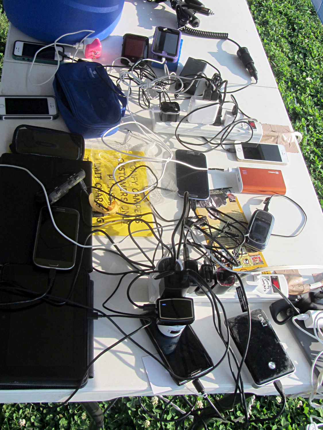
Everything you need to know about modern bicycle touring:
Cycling the Hudson Valley – Charging Station
The straight line along the right side of the map, from just below the New Croton Reservoir to Hopewell Junction, represents data loss from riding in a valley, plus knocking the coaxial power plug out of the battery pack where the South County Trail becomes one with Rt 100 / Saw Mill River Road for a few miles.
That last day had plenty of hillclimbing, even on the rail trail, but with a rewarding section of Rt 52 that drops 500 feet in a mile; I hit 41 mph while passing under I-84.
The audio quality was terrible, so I tried another bud with a foam windscreen over the hole and a hole punched in the middle of the double-sided white foam tape:
Earbud – foam over vent
The audio remained unintelligible, so I tried an upscale (but still cheap, because surplus) Koss earbud, first without blocking the vents and then with snippets of Kapton tape:
Koss earbud – tape over vent
The earphone has three slits on each side, but only the middle slit has a hole penetrating the case; it must be a stylin’ thing.
That sounded better, so I’ll roll with it. There’s supposed to be a foam cover over the housing, but those things always get grody and fall off; there’s not much point.
As nearly as I can tell, contemporary earbud designs optimize for volume (dBm/mV) and thumpin’ bass, all to the detriment of actual audio quality. Based on numerous samples over the years, there is zero correlation between price (admittedly, on the low end) and audio quality (admittedly, with my crappy hearing).
I own a pair of very nice (and thoroughly obsolete) Shure E2c sound-isolating ear beetles that sound great (even with my crappy hearing), but I’m unwilling to chop them up for the bike headset …
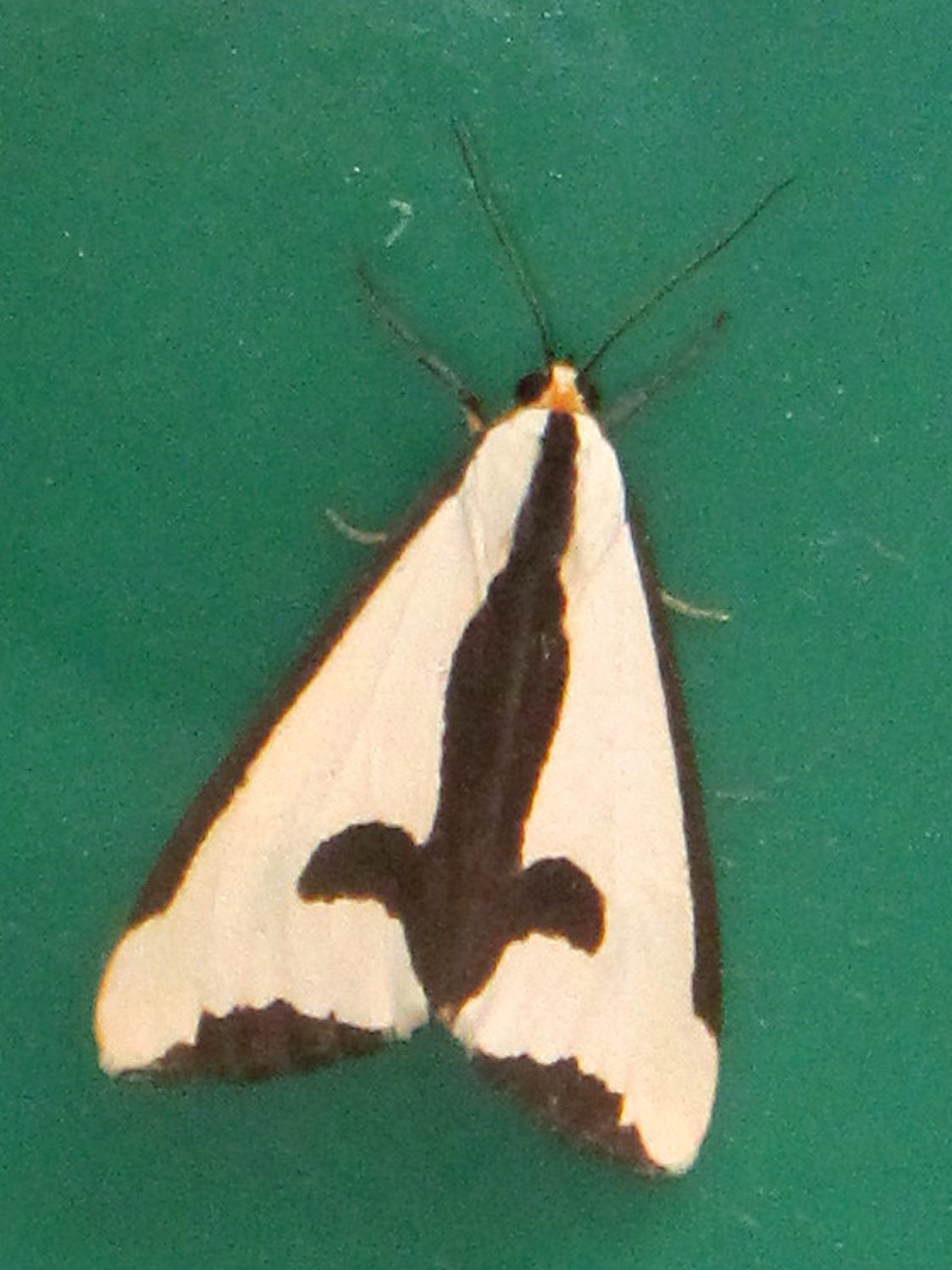
It’s a poor picture, but the moth was up and away after that; as always, the poor picture you get is better than the great picture you might have gotten.
A few days later, we spotted two of them on a brick wall, so there must be a bunch more out there.