Ed Nisley's Blog: Shop notes, electronics, firmware, machinery, 3D printing, laser cuttery, and curiosities. Contents: 100% human thinking, 0% AI slop.
First up: it’s not our projector, which means the usual Rules of Engagement do not apply.
A few small black plastic fragments fell out of the Epson S5 projector’s carry bag, the front foot wouldn’t remain extended, and, as one might expect, the two incidents were related. Mary needed it for the gardening class she was teaching the next evening, sooooo…
A pair of plastic snaps release the entire foot assembly from the front of the projector:
Epson S5 Projector Foot – assembled
It became obvious that we didn’t have all the fragments, but it was also obvious that, even if we had the pieces, a glued assembly wouldn’t last very long.
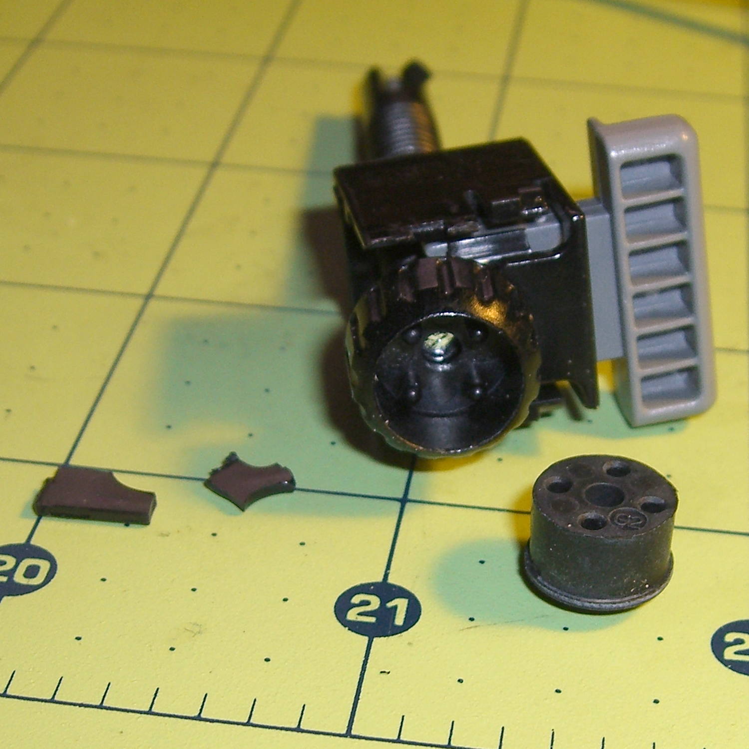
The threaded plastic stem surrounds a steel pin that’s visible when you remove the rubber foot pad. That pin holds the latch on the end of the stem outward, so that the stem can’t fall out. Drive out the pin with a (wait for it) pin punch inserted from the foot pad end, which reveals the broken plastic doodad:
Epson S5 Projector Foot – stem removed
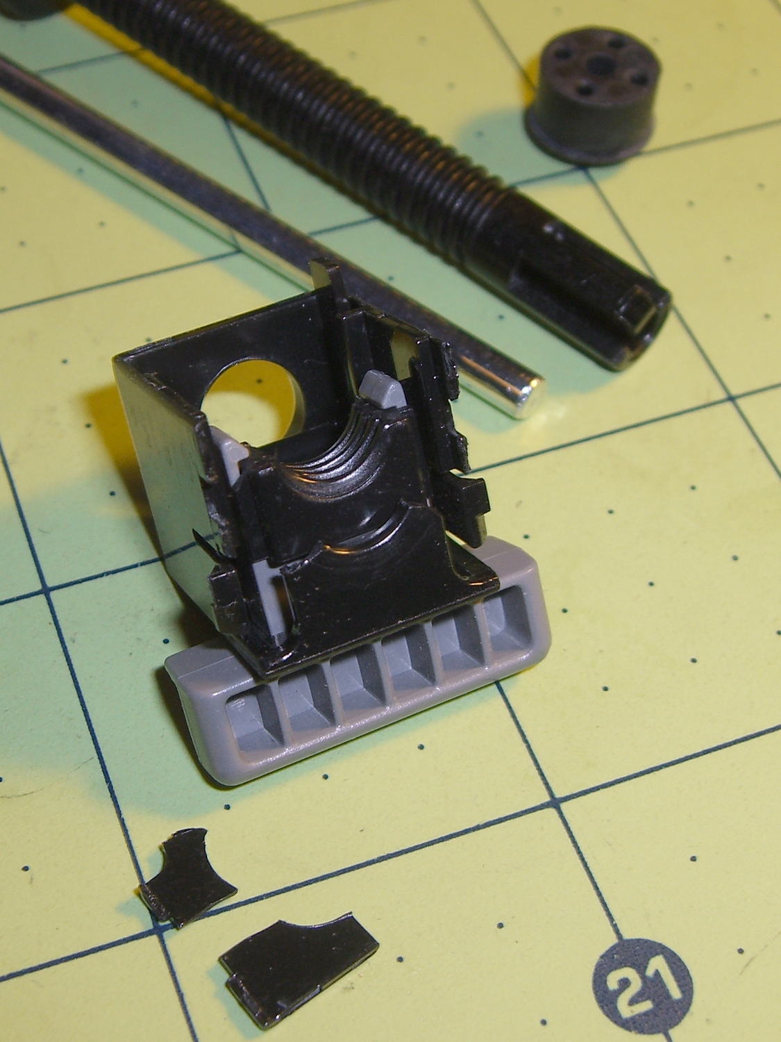
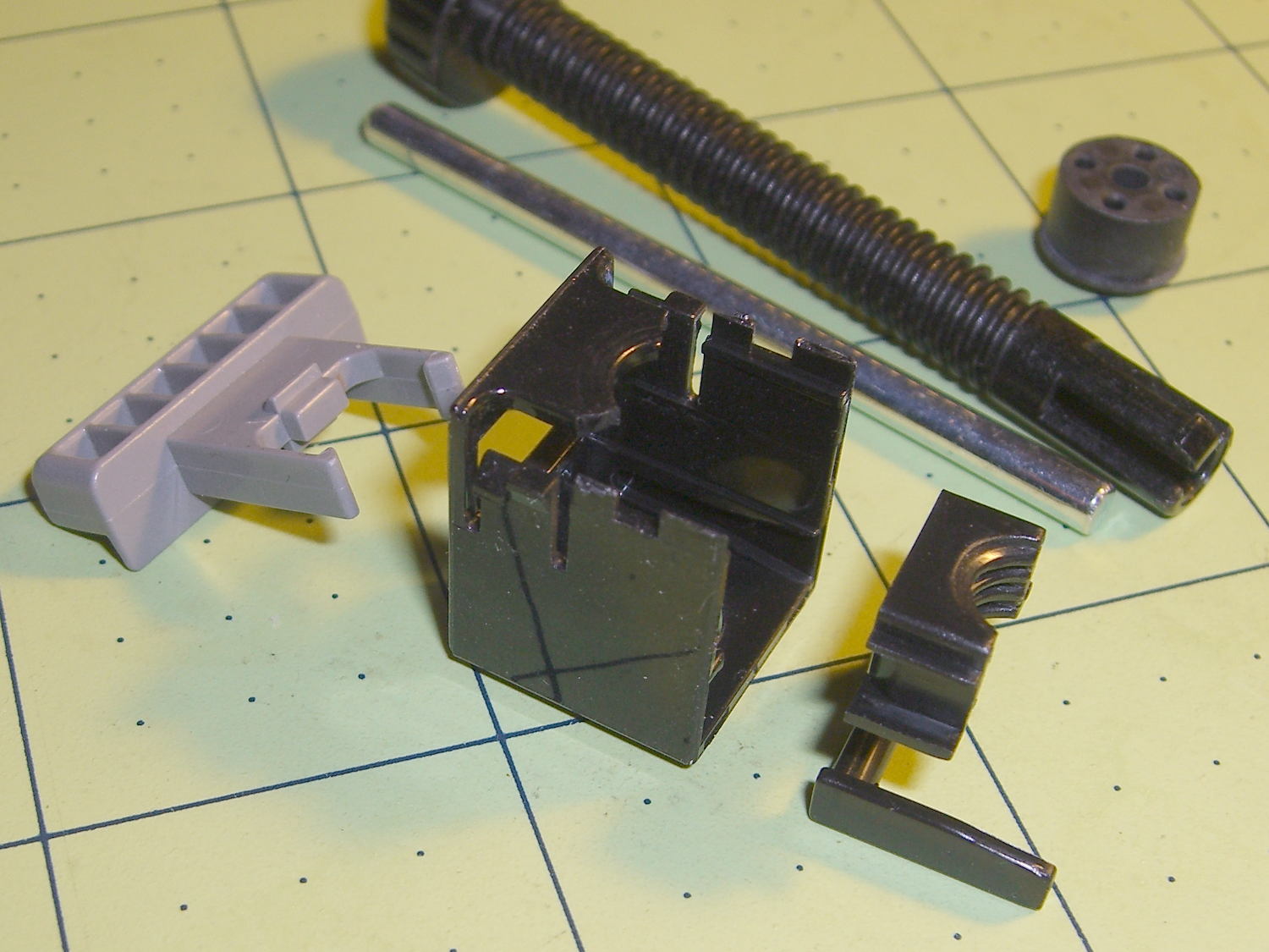
Release the latches on the gray handle and the intricate half-nut that engages the threaded stem slides out:
Epson S5 Projector Foot – disassembled
A plastic spring in the boxy shell pushes the gray handle and half-nut against the stem, holding the stem in place. Pushing the gray handle upward (on the projector, downward in the picture, yes, your fingertip can feel those ribs just fine) pulls the half-nut away from the stem and lets the stem slide freely. With the stem extended, the projector leans on the stem, pushes it against the half-nut, and you can fine-tune the angle by turning the stem; the splines around the rubber foot encourage that. You can pull the stem outward without activating the latch, which probably broke the fragile plastic plate.
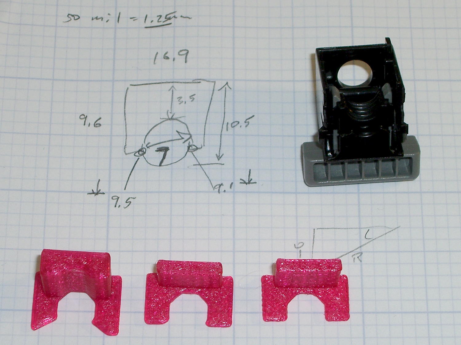
A doodle showing the estimated measurements, plus three 3D printed prototypes required to get a good fit:
Epson S5 Projector Foot – measurements and versions
The solid model looks about like you’d expect:
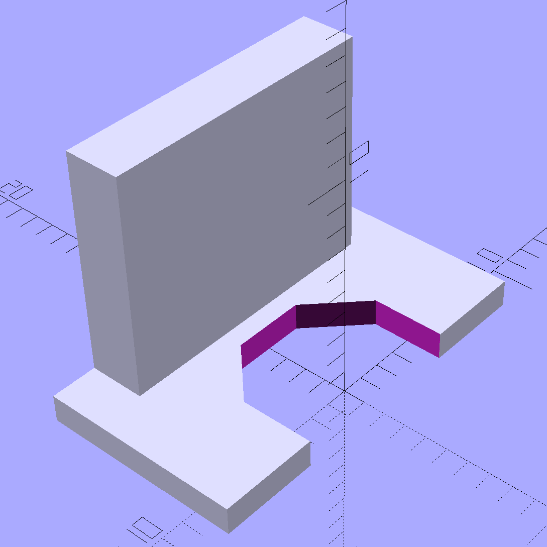
Epson S5 Projector foot latch – solid model
The first version (leftmost of the three sitting on the doodle, above) had angled ends on the tabs that I intended to match up with the stubs remaining on the OEM latch. The part fit better with shorter tabs and the angles vanished on third version; the statements remain in the OpenSCAD source, but the short tabs render them moot.
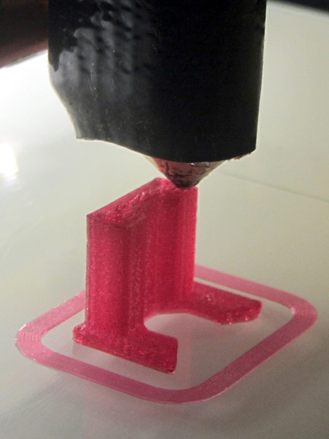
Apparently I got the cooling & fan & minimum layer time pretty close to right for PETG, as each of those three towers printed singly with no slumping:
Epson S5 Projector Foot – V1 on platform
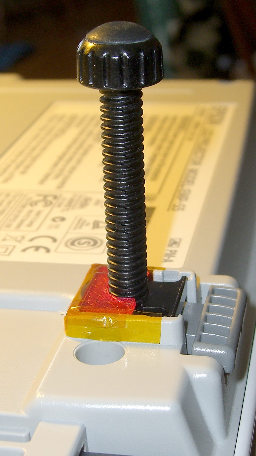
The third version snapped into place, with a square of tapeless sticky on the back to help keep it there. The obligatory Kapton tape helps retain it, but I have no illusions about the permanence of this repair:
Epson S5 Projector Foot – repair installed
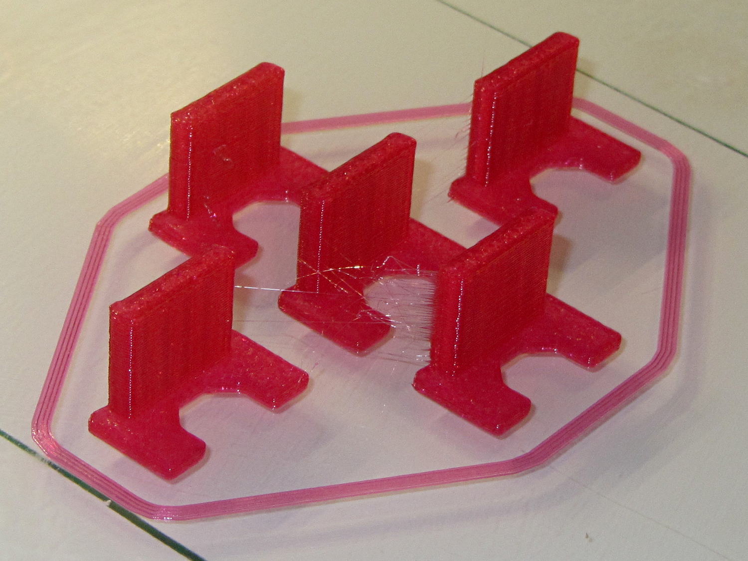
Because I know the problem will happen again, I called for backup:
Epson S5 Projector Foot – 5 copies
That’s with Hilbert Curve top / bottom fill, three top / bottom layers, 20% rectilinear infill, and two perimeters. Extruder at 250 °C, platform at 90 °C, hairspray for adhesion.
Note, however, the hair-fine strings connecting the towers. Retraction must be just about right, as shown by the overall quality of the objects, but PETG comes out really stringy. Choosing an infill pattern to minimize retraction seems like a big win; relatively sparse 3D Honeycomb works well on larger objects, but these were so small that straight line fill fit better. The flat plates on the bottom consist of five completely solid layers of PETG.
Reports from the field indicate complete success: whew!
One could, of course, just buy a replacement from the usual eBay supplier, if one were so inclined.
The remainder are closer to 1.4 mm = 3.3 threads, with the preview showing Slic3r allowed a narrow gap that doesn’t appear in real life:
Chain Mail – 3.3 wide – Slic3r preview – link bridge layer
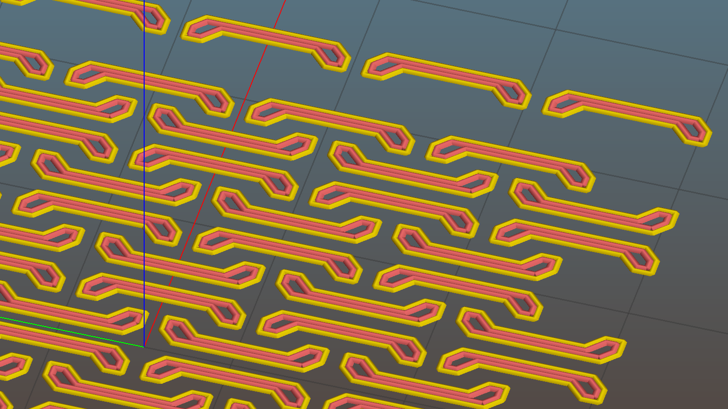
What’s important about this is that the bridging worked perfectly: all the links emerged free of their neighbors and the patch flexed along both axes.
Chain mail – 6 and 4 thread
I tried this on one layer of Elmer’s White Glue, diluted 1:3 with water, and the links bonded firmly. I’d had some trouble with a few links popping off the usual hairspray after the first few layers, so I decided to try something different.
The fine hair strands have mostly Gone Away, perhaps due to using Concentric infill.
All in all, PETG looks pretty good, even if it’s just as hard to photograph as red PLA.
Update: You may prefer the source code as a GitHub gist.
The OpenSCAD source code:
// Chain Mail Armor Buttons
// Ed Nisley KE4ZNU - December 2014

Layout = "Build";			// Link Button LB Joiner Joiners Build PillarMod

//-------
//- Extrusion parameters must match reality!
//  Print with 1 shell and 2+2 solid layers

ThreadThick = 0.25;
ThreadWidth = 0.40;

HoleWindage = 0.2;

Protrusion = 0.1; 				// make holes end cleanly

function IntegerMultiple(Size,Unit) = Unit * ceil(Size / Unit);

//-------
// Dimensions

//- Set maximum sheet size

SheetSizeX = 55;	// 170 for full sheet on M2
SheetSizeY = 55;	// 230 ...

//- Diamond or rectangular sheet?

Diamond = false;					// true = rotate 45 degrees, false = 0 degrees for square

BendAround = "X";					// X or Y = maximum flexibility *around* designated axis

Cap = true;										// true = build bridge layers over links
CapThick = 4 * ThreadThick;						// flat cap on link: >= 3 layers for solid bridging

Armor = true && Cap;							// true = build armor button atop (required) cap
ArmorThick = IntegerMultiple(2.0,ThreadThick);	// height above cap surface

ArmorSides = 4;
ArmorAngle = true ? 180/ArmorSides : 0;			// true -> rotate half a side for best alignment

//- Link bar sizes

BarThick = 3 * ThreadThick;
BarWidth = 3.3 * ThreadWidth;

BarClearance = 4 * ThreadThick;		// vertical clearance above & below bars

VertexHack = 0;						// 0 = no, 1 = slightly reduce openings to avoid coincident vertices

//- Compute link sizes from those values

//- Absolute minimum base link: bar width + corner angle + build clearance around bars
//  rounded up to multiple of thread width to ensure clean filling
BaseSide = IntegerMultiple((4*BarWidth + 2*BarWidth/sqrt(2) + 3*(2*ThreadWidth)),ThreadWidth);

BaseHeight = 2*BarThick + BarClearance;           // both bars + clearance

echo(str("BaseSide: ",BaseSide," BaseHeight: ",BaseHeight));
//echo(str(" Base elements: ",4*BarWidth,", ",2*BarWidth/sqrt(2),", ",3*(2*ThreadWidth)));
//echo(str(" total: ",(4*BarWidth + 2*BarWidth/sqrt(2) + 3*(2*ThreadWidth))));

BaseOutDiagonal = BaseSide*sqrt(2) - BarWidth;
BaseInDiagonal = BaseSide*sqrt(2) - 2*(BarWidth/2 + BarWidth*sqrt(2));

echo(str("Outside diagonal: ",BaseOutDiagonal));

//- On-center distance measured along coordinate axis
//   the links are interlaced, so this is half of what you think it should be...

LinkOC = BaseSide/2 + ThreadWidth;

LinkSpacing = Diamond ? (sqrt(2)*LinkOC) : LinkOC;
echo(str("Base spacing: ",LinkSpacing));

//- Compute how many links fit in sheet

MinLinksX = ceil((SheetSizeX - (Diamond ? BaseOutDiagonal : BaseSide)) / LinkSpacing);
MinLinksY = ceil((SheetSizeY - (Diamond ? BaseOutDiagonal : BaseSide)) / LinkSpacing);
echo(str("MinLinks X: ",MinLinksX," Y: ",MinLinksY));

NumLinksX = ((0 == (MinLinksX % 2)) && !Diamond) ? MinLinksX + 1 : MinLinksX;
NumLinksY = ((0 == (MinLinksY % 2) && !Diamond)) ? MinLinksY + 1 : MinLinksY;
echo(str("Links X: ",NumLinksX," Y: ",NumLinksY));

//- Armor button base

ButtonHeight = BaseHeight + BarClearance + CapThick;
echo(str("ButtonHeight: ",ButtonHeight));

//- Armor ornament size & shape
//	 Fine-tune OD & ID to suit the number of sides...

TotalHeight = ButtonHeight + ArmorThick;
echo(str("Overall Armor Height: ",TotalHeight));

ArmorOD = 1.0 * BaseSide;						// tune for best base fit
ArmorID = 10 * ThreadWidth;						// make the tip blunt & strong

//-------

module ShowPegGrid(Space = 10.0,Size = 1.0) {

  RangeX = floor(95 / Space);
  RangeY = floor(125 / Space);

	for (x=[-RangeX:RangeX])
	  for (y=[-RangeY:RangeY])
		translate([x*Space,y*Space,Size/2])
		  %cube(Size,center=true);

}


//-------
// Create link with armor button as needed

module Link(Topping = false) {

LinkHeight = (Topping && Cap) ? ButtonHeight : BaseHeight;

render(convexity=3)
rotate((BendAround == "X") ? 90 : 0)
	rotate(Diamond ? 45 : 0)
		union() {
			difference() {
				translate([0,0,LinkHeight/2])									// outside shape
					intersection() {
						cube([BaseSide,BaseSide,LinkHeight],center=true);
						rotate(45)
							cube([BaseOutDiagonal,BaseOutDiagonal,(LinkHeight + 2*Protrusion)],center=true);
					}

				translate([0,0,(BaseHeight + BarClearance + 0*ThreadThick - Protrusion)/2])
					intersection() {											// inside shape
						cube([(BaseSide - 2*BarWidth),
								(BaseSide - 2*BarWidth),
								(BaseHeight + BarClearance + 0*ThreadThick + VertexHack*Protrusion/2)],
								center=true);
						rotate(45)
							cube([BaseInDiagonal,
									BaseInDiagonal,
									(BaseHeight + BarClearance + 0*ThreadThick + VertexHack*Protrusion/2)],
									center=true);
					}

				translate([0,0,((BarThick + 2*BarClearance)/2 + BarThick)])		// openings for bars
					cube([(BaseSide - 2*BarWidth - 2*BarWidth/sqrt(2) - VertexHack*Protrusion/2),
						(2*BaseSide),
						BarThick + 2*BarClearance - Protrusion],
						center=true);

				translate([0,0,(BaseHeight/2 - BarThick)])
					cube([(2*BaseSide),
						(BaseSide - 2*BarWidth - 2*BarWidth/sqrt(2) - VertexHack*Protrusion/2),
						BaseHeight],
						center=true);

			}

 			if (Topping && Armor)
				translate([0,0,(ButtonHeight - Protrusion)])		// sink slightly into the cap
					rotate(ArmorAngle)
					cylinder(d1=ArmorOD,d2=ArmorID,h=(ArmorThick + Protrusion), $fn=ArmorSides);
		}

}


//-------
// Create split buttons to join sheets

module Joiner() {

	translate([-LinkSpacing,0,0])
		difference() {
			Link(false);
			translate([0,0,BarThick + BarClearance + TotalHeight/2 - Protrusion])
				cube([2*LinkSpacing,2*LinkSpacing,TotalHeight],center=true);
		}

	translate([LinkSpacing,0,0])
		intersection() {
			translate([0,0,-(BarThick + BarClearance)])
				Link(true);
			translate([0,0,TotalHeight/2])
				cube([2*LinkSpacing,2*LinkSpacing,TotalHeight],center=true);
		}

}


//-------
// Build it!

//ShowPegGrid();

if (Layout == "Link") {
	Link(false);
}

if (Layout == "Button") {
	Link(true);
}

if (Layout == "LB") {
	color("Brown") Link(true);
	translate([LinkSpacing,LinkSpacing,0])
		color("Orange") Link(false);
}

if (Layout == "Build")
	for (ix = [0:(NumLinksX - 1)],
		 iy = [0:(NumLinksY - 1)]) {
			x = (ix - (NumLinksX - 1)/2)*LinkSpacing;
			y = (iy - (NumLinksY - 1)/2)*LinkSpacing;
			translate([x,y,0])
			color([(ix/(NumLinksX - 1)),(iy/(NumLinksY - 1)),1.0])
				if (Diamond)
					Link((ix + iy) % 2);					// armor at odd,odd & even,even points
				else
					if ((iy % 2) && (ix % 2))				// armor at odd,odd points
                        Link(true);
					else if (!(iy % 2) && !(ix % 2))		// connectors at even,even points
						Link(false);
	}

if (Layout == "Joiner")
	Joiner();

if (Layout == "Joiners") {
	NumJoiners = max(MinLinksX,MinLinksY)/2;
	for (iy = [0:(NumJoiners - 1)]) {
		y = (iy - (NumJoiners - 1)/2)*2*LinkSpacing + LinkSpacing/2;
		translate([0,y,0])
			color([0.5,(iy/(NumJoiners - 1)),1.0])
				Joiner();
	}
}

if (Layout == "PillarMod")					// Slic3r modification volume to eliminate pillar infill
	translate([0,0,(BaseHeight + BarClearance)/2])
		cube([1.5*SheetSizeX,1.5*SheetSizeY,BaseHeight + BarClearance],center=true);
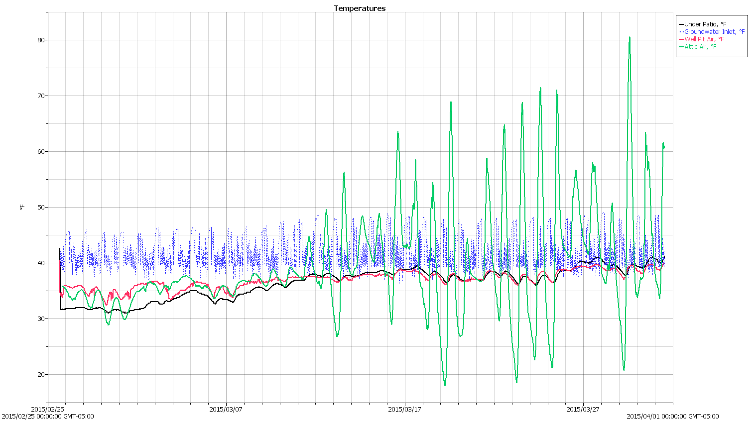
The blue trace shows the groundwater temperature at the inlet pipe. The minimum values should be pretty close to the actual ground temperature about four feet down, which seems roughly constant at 37 °F for March.
The red trace comes from the datalogger dangling in the well pit in the back yard, directly under one of the vent holes, so it’s recording the air temperature in a below-grade chamber.
The green trace shows the attic air temperature, which is strongly influenced by sun on the (white) asphalt shingle roof. That said, the air temperature gets a lot lower than any of the below-grade loggers; it’s fair to say they’re recording something fairly close to the actual ground temperature.
The already ponderous chunk of G-Code that slic3r prepends to the outgoing file got a bit more complex with all the changes going on around here.
As it stands now, the starting G-Code looks like this:
;-- Slic3r Start G-Code for M2 starts --
;  Ed Nisley KE4NZU - 2015-03-07
;  Makergear V4 hot end
; Z-min switch at platform, must move nozzle to X=135 to clear
M140 S[first_layer_bed_temperature]	; start bed heating
G90				; absolute coordinates
G21				; millimeters
M83				; relative extrusion distance
M17				; enable steppers
G4 P500			;  ... wait for power up
G92 Z0			; set Z to zero, wherever it might be now
G1 Z10 F1000	; move platform downward to clear nozzle; may crash at bottom
G28 Y0			; home Y to clear plate, origin in middle
G92 Y-127
G28 X0			; home X, origin in middle
G92 X-100
G1 X130 Y0 F15000	; move off platform to right side, center Y
G28 Z0			; home Z to platform switch, with measured offset
G92 Z-2.10
G0 Z2.0			; get air under switch
G0 Y-127 F10000	; set up for priming, zig around corner
G0 X0			;  center X
G0 Y-125.0		; just over platform edge
G0 Z0 F500	; exactly at platform
M109 S[first_layer_temperature]	; set extruder temperature and wait
M190 S[first_layer_bed_temperature]	; wait for bed to finish heating
G1 E20 F300		; prime to get pressure, generate blob on edge
G0 Y-123 F500		; shear off blob
G1 X15 F15000	; jerk away from blob, move over surface
G4 P500			; pause to attach
G1 X45 F500		; slowly smear snot to clear nozzle
G1 Z1.0 F2000	; clear bed for travel
;-- Slic3r Start G-Code ends --
The blow-by-blow description…
Lines 9-10: Manually enable stepper drivers and wait half a second
Changing to a 24 V power supply for the motors doesn’t affect the winding current (because the drivers control that), but it does increase the current’s rate-of-change (because inductor voltage = L di/dt and the applied voltage is 26% higher) during each microstep. That means the motors snap to a whole-step position a bit faster when the Marlin firmware enables the drivers and the higher di/dt induces more glitch voltage in, say, the endstop cable, triggering a false contact sense (as the circuit depends on the Arduino’s 20+ kΩ internal pullup resistor). In any event, a half-second snooze avoids the problem.
Lines 18-19: Home Z-axis & set platform switch offset
The only way to set the offset accurately is to compare the actual height of a printed object (or the skirt around it) with the nominal value. I use 5 mm tall thinwall open boxes and, after setting the Extrusion Multiplier properly, they’re good test objects.
Lines 22-24: Extruder final heating
PETG tends to stick to the nozzle, so the nozzle now sits just over the edge of the glass plate and flush with the top surface, so that the initial drool forms a glob anchored to the side of the plate. It looks like this:
V4 PETG – preheat position
Notice the curl attached to the nozzle: I generally pick those off with a tweezer, but let this one remain to show how this mess works.
Line 31: Prime the extruder
With the hot end and platform temperatures stabilized, I ram 20 mm of filament into the extruder to refill it and stabilize its internal pressure. Because it’s been drooling ever since the plastic melted, not very much plastic comes out, but what does emerge enlarges the blob and bonds with the plastic stuck on the nozzle, thusly:
V4 PETG – extruder priming
Lines 28-29: Detach the blob
Moving 2 mm onto the platform leaves most of the snot hanging on the edge of the glass, with just a bit on the far side of the nozzle. Doing that relatively slowly gives the plastic time to flow around the nozzle and remain with the blob, then zipping to X=15 encourages it to detach.
Lines 30-31: Wipe away what’s left
Pause for half a second to allow whatever’s left to attach to the platform, then slowly move to X=45, and watch the remaining snot leave a trail on the platform as it oozes off the nozzle.
Then hop up 1 mm to clear the platform and pass control to the rest of the G-Code with a clean nozzle!
That’s the ideal outcome, of course. Sometimes a recalcitrant blob hangs on, but it generally oozes off while the nozzle trudges around three skirt outlines…
The solid box lets you check the outside dimensions (20 x 20 x 5 mm) and the slicer’s infill parameters.
The first few attempts with a new setup won’t look very good, but that’s the whole point:
M2 V4 Calibration Objects
Getting a workable profile and accurate Z-axis setting required maybe a dozen quick prints & parameter changes. After that, they’re good for verifying that any change you make hasn’t screwed up something beyond recovery.
Put five of them on the platform to verify overall alignment (“leveling”) and first-layer thickness:
Thinwall Calibration Cubes – 5 copies
A few iterations will generate plenty of show-n-tell tchotchkes:
Thinwall open boxes from platform leveling
As nearly as I can tell, if you can’t print these reliably, there’s no point in trying to print anything else.
Even better, when you suddenly can’t print anything else reliably, these simple boxes will tell you what’s gone wrong…
The turkey flock that normally lives along the Wappingers Creek valley, downslope from the back yard, has emerged for the ritual spring foraging:
Turkey flock – 0
And posturing:
Turkey flock – 1
And just moseying around:
Turkey flock – 2
You can match the trees and identify some duplicated birds, but the flock seems stable around a dozen. They used to deploy skirmish lines upwards of two dozen bird and we’ve recently counted 19; we think foxes have been encouraging better control of wandering chicks.