Ed Nisley's Blog: Shop notes, electronics, firmware, machinery, 3D printing, laser cuttery, and curiosities. Contents: 100% human thinking, 0% AI slop.
Restocking the AA and AAA alkaline cell supply delivered this example of underprotection from Amazon:
Amazon Packaging – alkaline batteries
I think that scrap of plastic was once an air pillow, but it sure didn’t last long and definitely didn’t fill the entire space around the boxes.
Allowing that much mass to thrash around inside the box can’t possibly be a Good Thing, even if the cells weren’t damaged. One would hope they’d do a better job with lithium cells.
The shelf that collects old hard drives filled up, so I’ve been wiping the data before recycling them. This takes a while, but we know what happens when your hardware falls into unexpected hands. The routine goes a little something like this…
Set the drive’s jumper to Master, plug the drive into the USB adapter, plug the adapter directly into a USB port on the PC (because outboard hubs tend to be flaky), make sure there’s no valuable data, unmount.
time sudo dd if=/dev/urandom of=/dev/sdc bs=4096
[sudo] password for ed:
dd: error writing ‘/dev/sdc’: No space left on device
73259047+0 records in
73259046+0 records out
300069052416 bytes (300 GB) copied, 22276.7 s, 13.5 MB/s

real	371m19.003s
user	0m22.884s
sys		370m34.906s
Good old dd works for me; the only trick is not obliterating the system’s main hard drive with a simple finger fumble. Numbers from /dev/urandom suffice for this purpose; that’s where most of the packaged programs get their data, too. I do hardcore style, just because.
Ordinary desktop drives, at least those from long ago, can write at a bit over 12 MB/s → 40 GB/h on the average, with the higher peak rates that generally appear in the drive descriptions remaining an occasional sight. They won’t go much faster, even when plugged directly into the system board, but it’s not as if I sit there waiting until it’s done. USB 2.0 “high speed” transfers can hit 60 MB/s, including all the overhead, so that’s not the limiting factor; I’d expect the adapter’s firmware to throttle the data long before the bus strangles.
Use gparted to write a fresh partition table with a single NTFS (because the next user will probably run Windows) partition labeled Scrubbed spanning the entire drive.
Then stack the drive neatly on the outbound heap:
Scrubbed hard drives
That cardboard box isn’t quite as full of unscrubbed drives as it was a few weeks ago.
The stack in the back contains all those worthless 30 to 80 GB 5400 RPM drives from old Dells, plus a few 1.5 and 2.0 (!) GB drives from who knows where. I have a plan for those platters…
If the 1-48 on the side of the tube base (facing away in the picture) means anything, then General Electric built it in January 1948.
The pinout view in the datasheet assumes you’re looking at the bottom of the socket, which makes perfect sense given the hand-wired chassis construction techniques of the day:
0D3 Voltage Regulator Tube – pinout
So the view is backwards when seen from the top, not that you’d ever need it:
Ceramic octal tube socket – 0D3 pinout
The internal jumper across pins 3-7 allows you to disconnect the downstream circuit when the regulator isn’t in the socket, which is a Very Good Idea with a shunt regulator.
Not having a 200 V power supply ready to hand, but having recently restocked the 9 V alkaline battery box, this actually worked:
0D3 voltage regulator test setup
That’s 16 x 9-ish V = 150 V across the battery terminals, plus a 50 V adjustable bench power supply coming in on clip leads from the upper right, with current shown on a digital panel meter across a 1 Ω sense resistor. The classic 1.5 kΩ carbon resistor emerged from from a coffee can of parts that Came With The House™ and seemed appropriate for the occasion.
The tube conducts a few milliamps through a small plasma filament discharge at 150 V. The current ramps up to about 10 mA as the supply voltage increases to 180 V, whereupon the tube fires and the current jumps to 30 mA (which is less than the spec, but I ran the power supply in constant-current mode to avoid whoopsies).
Reducing the current to 10 mA slightly reduces the area involved in the plasma discharge, but the tube still produces a nice display through the mica spacer / insulator atop the plate:
0D3 voltage regulator – 10 mA current
That isn’t quite in focus, but should give you the general idea.
I didn’t measure the operating voltages across the tube, mostly because I didn’t want more cheap clip leads cluttering the bench.
It’d make a very low intensity nightlight that dissipates a watt or two. Boosting the current to the absolute maximum 40 mA would brighten it up a bit, but dissipating 6 W in the tube probably won’t do it any good.
This obviously calls for an Arduino monitoring the tube current with a Hall-effect sensor and regulating it with a hulking MOSFET…
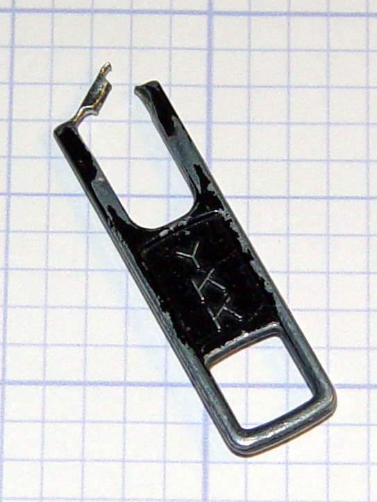
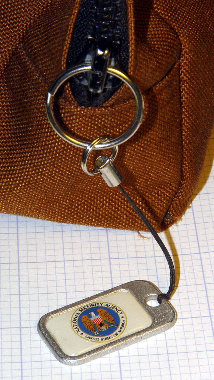
The NSA pull tabwent missing from my belt pack on the way back from a Squidwrench meeting and, despite diligent searching, remained missing for a several weeks. It reappeared from far under the Forester’s front seat, still attached to the severely eroded YKK zipper pull tab:
Eroded YKK Zipper Tab
A stout jump ring from the heap should avoid that problem for the foreseeable future:
You never realize how big automobile tires are, until you see them out of context:
Forester loaded with Sienna snows
The Sienna spends its days commuting near what used to be the engineering glory of Rt 128, and snow season is comin’ on strong. We hauled the snows out and the summer tires back on our way to a brief vacation on Cape Cod.
I have no illusions that the two ratcheting straps on each pair of tires + wheels will hold them in place during an actual crash, but at least they’re not rattling around. The tiedown points next to the hatch have a 20 kg load limit, which is pretty close to the weight of a single tire + wheel. The rear seat anchors aren’t rated as tiedown points, but, hey, if they can hold the seat up during a crash, they’re good enough for me.
We’ve always packed lightly and, these days, we bring no more than absolutely necessary. Those tires sure didn’t leave room for much else…