Ed Nisley's Blog: Shop notes, electronics, firmware, machinery, 3D printing, laser cuttery, and curiosities. Contents: 100% human thinking, 0% AI slop.
The latest new-to-me off-lease Dell PC arrived with Windows 7, which means that I must install UltraVNC (that’s uvnc.com, not the obvious URL, alas) to enable remote desktop access. Here’s what the download page looks like through a fresh copy of Firefox, without ad blocking:
UltraVNC Download – with ads
Notice that the prominent “Start Download” label-and-button in the middle of the page isn’t the one you want, nor are any of the other things that say “Download”. If you’re not a techie and don’t quite know what you’re looking for, there’s no hope for you.
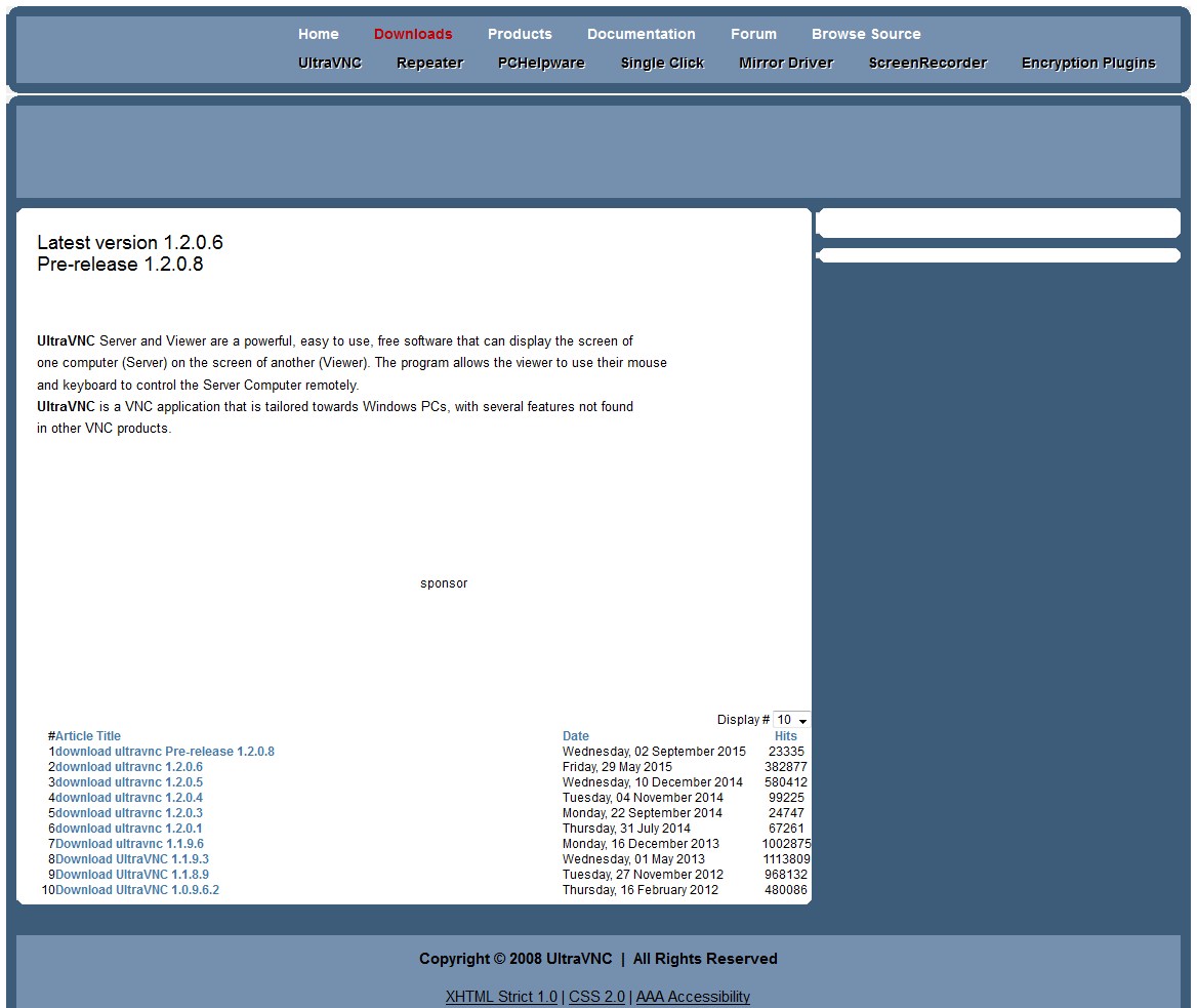
Here’s what it looks like with all the ads suppressed:
UltraVNC Download – minus ads
Granted, that’s not the most user-friendly download site I’ve ever seen and, most likely, non-techies won’t venture there, but … suppressing the ads certainly eliminates a tremendous amount of noise.
WordPress places ads on my blog and I get a cut of the revenue, so I am not without a certain conflict of interest. I could forego the ad revenue (currently about 60 ¢/day), which wouldn’t eliminate the ads; WordPress simply pockets my cut in addition to theirs. I could also pay WordPress 30 ¢/day to completely suppress the ads (and get other features I don’t care about), for a net cost of a dollar a day to not show ads.
Hey, who wants to sign up as a Patreon donor? [grin]
Back in the day, this surely represented an achievement in high-density electronics packaging:
Electronics Block – 1
A view from the other corner suggests the layout wasn’t quite right:
Electronics Block – 2
It has no identification, the transistors have house numbers, and the PCB looks like a prototype. As nearly as I can tell from the capacitor date codes, it dates back to the mid-1960s.
Judging from the ugly solder and dislodged via rings, somebody had to apply extensive modifications after initial assembly; it trailed half a dozen red wires soldered to vias and components.
In 1991 we lived in Tolland CT, where I took one picture of a maple twig every week:
This slideshow requires JavaScript.
That was with a film camera, of course, with negatives. I assembled the printed images into a poster and eventually (perhaps in 2001) scanned / digitally photographed them four-at-a-time, saved the result as a 330 MB Photoshop file with one 2×2 group in each of 13 layers (there are 50 images, probably because vacations), and burned that to a CD.
All I can say: it must have made sense at the time.
Anyhow, here in the future, I found that CD in a pile destined for the shredder, which shouldn’t ought to happen without some attention.
Here’s how I extracted the separate images from that file into standalone JPEGs, cropped them to a uniform size, and smushed them to suitably low quality:
convert A\ Year\ in\ the\ Life\ of\ Tolland\ CT\ -\ 1991.psd -quality 95 Tolland-1991-%02d.jpg
for f in {01..13} ; do convert Tolland-1991-$f.jpg -crop "1212x1775+0+0" img-$f-0.jpg ; done
for f in {01..13} ; do convert Tolland-1991-$f.jpg -crop "1212x1775+1212+0" img-$f-1.jpg ; done
for f in {01..13} ; do convert Tolland-1991-$f.jpg -crop "1212x1775+0+1775" img-$f-2.jpg ; done
for f in {01..13} ; do convert Tolland-1991-$f.jpg -crop "1212x1775+1212+1775" img-$f-3.jpg ; done
for f in {01..13} ; do for g in {0..3} ; do convert img-$f-$g.jpg -crop "1100x1650+50+50" out-$f-$g.jpg ; done ; done
sn=1 ; for f in {01..13} ; do for g in {0..3} ; do printf -v dn 'Tolland-1991-Maple-%02d.jpg' "$(( sn++ ))" ; convert img-$f-$g.jpg -crop "1100x1650+50+50" +repage -rotate 90 -define jpeg:extent=200KB $dn ; done ; done
Then WordPress assembles the 50 images into a slide show.
Of course, it didn’t go quite as smoothly as all that, but it took maybe half an hour of fiddling to get it right by iterating on the commands until I liked the results. One might tweak the exposures and suchlike, but that’s in the nature of fine tuning.
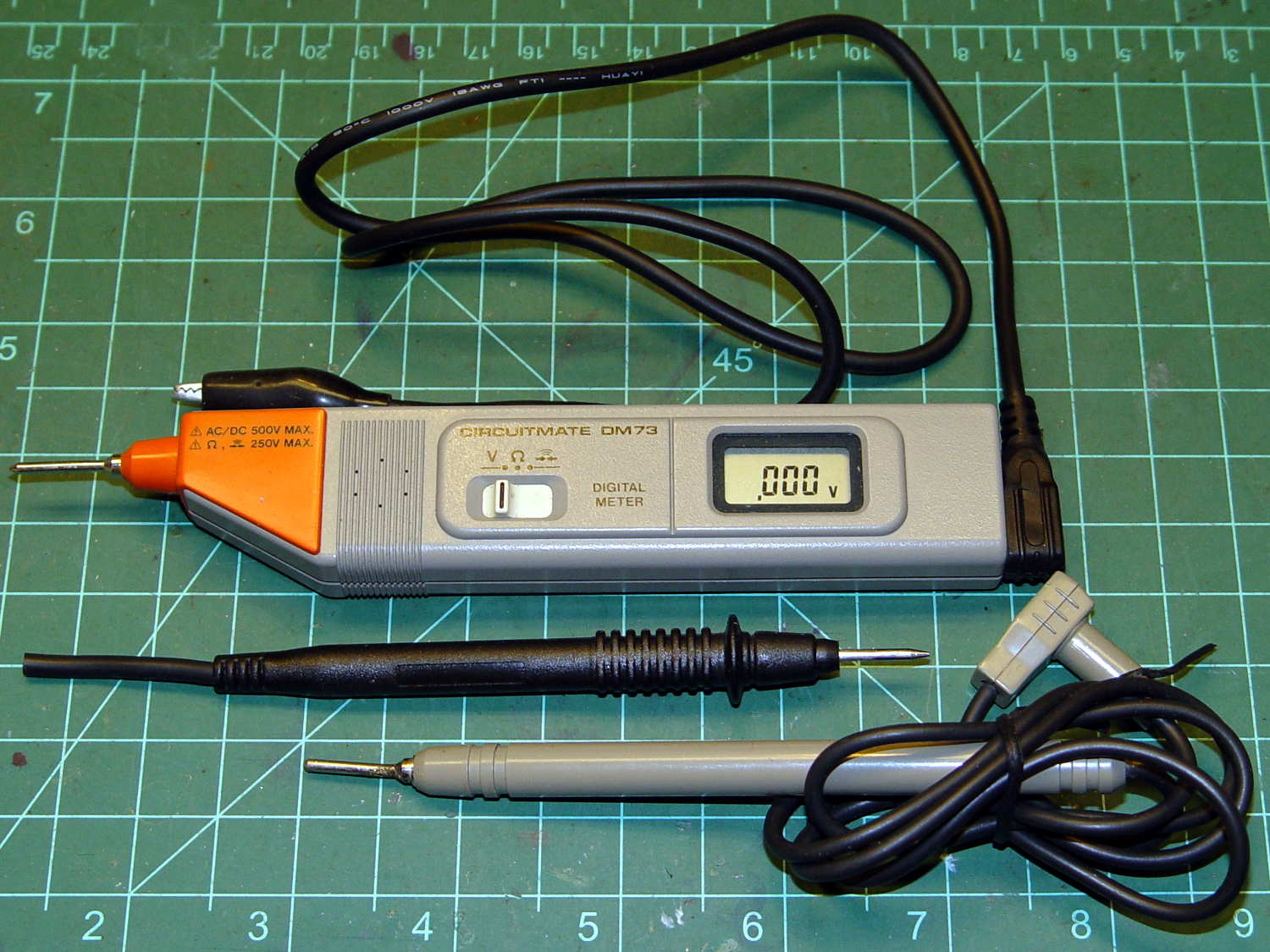
Although it’s rated to 500 V, it violates the fundamental principle of high-voltage electronics debugging:
Always keep one hand in your pocket!
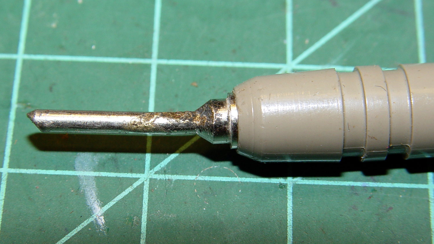
The scorched and truncated probe tip on the “ground wire” shows Phil slipped at least once:
Beckman DM73 – probe tip
After far too long, I sacrificed a black multimeter probe from the heap, soldered an alligator clip on the end, and, henceforth, will use it appropriately. Mostly, I never do any high-voltage work, but you never know.
I suppose I should splice that nice black probe onto the end of the Beckman wire for low-voltage work…
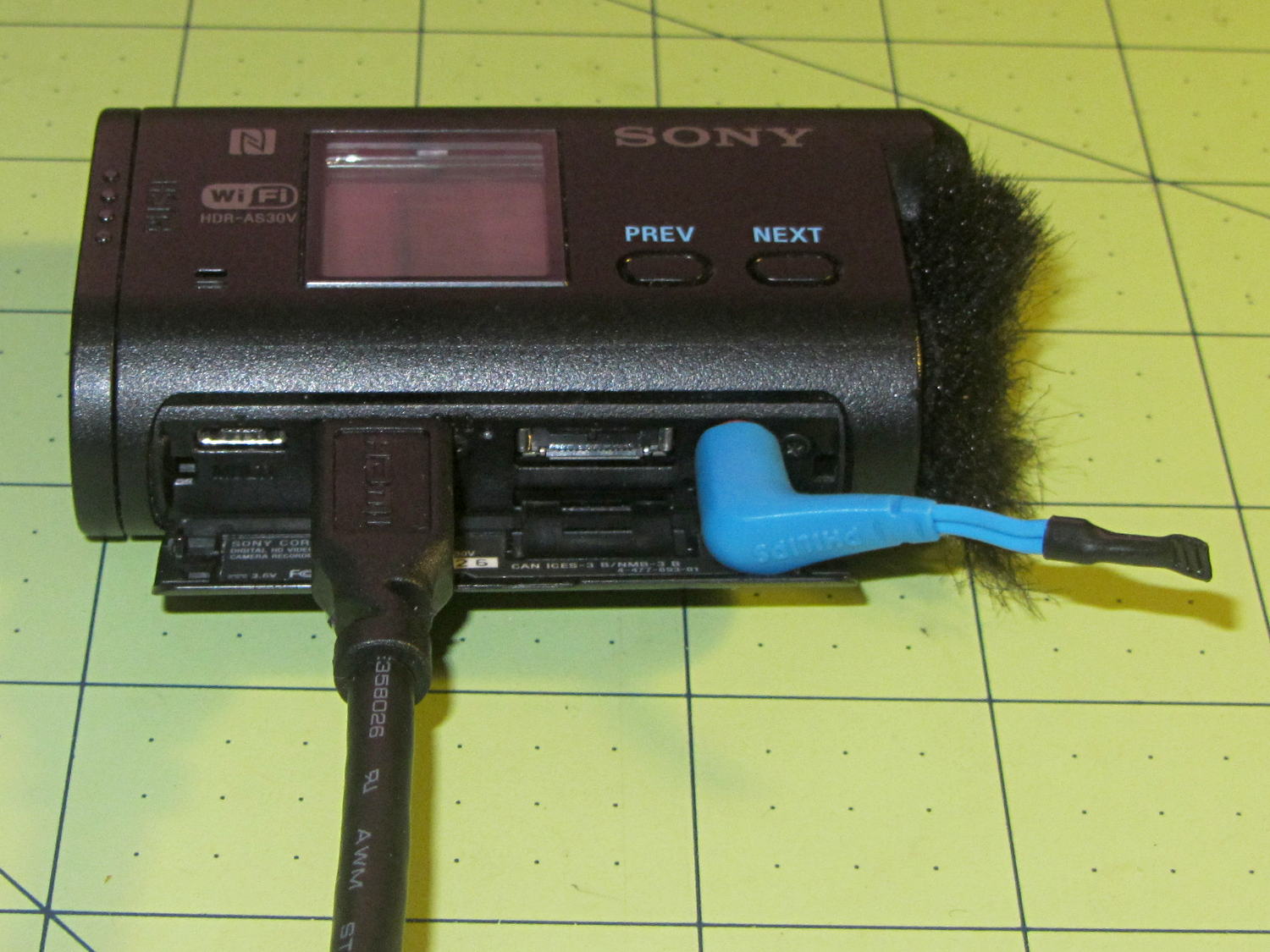
The Sony HDR-AS30V has extremely high audio gain, which is precisely what you need for the mic on an action camera. It sends that audio, along with the video, through its HDMI output, so when you drive a display from the camera in enclosed space, the audio is REALLY LOUD and causes severe feedback. For obscure reasons, given the staggering cost of the venue’s AV system, there’s no way to mute the audio channel of the video input when you’re also using a mic attached to someone giving a presentation.
The obvious solution, a shorted jumper (formerly an earbud plug) in the external mic jack, looked like this:
Sony HDR-AS30V – Dummy external mic
Contrary to what I expected, the camera doesn’t disable the internal mic with the jumper in place. The amp probably uses an analog multiplexer, rather than a mechanical switch, and even an off-channel isolation of, say, 76 dB (from the MAX4544 spec, for example) isn’t enough to completely mute the mic. You could, given sufficient motivation, measure the actual isolation, but the surviving audio isn’t subtle at all.
The not-obvious solution turned out to be putting the camera into either single or interval photo mode, rather than the movie mode I use for bike rides. It seems that when the video format doesn’t require audio, the camera either disables the audio inputs or (more likely) just doesn’t include audio data in the HDMI output.
Which produces exactly what I want: a video output with no accompanying audio.
Recently, the eye cups became difficult to pull out. The problem seemed to lie in the seal around the exterior of each tube, rather than with the internal mechanism, so I eased the tiniest possible drop of clock oil into each gap, spun the tubes, cycled them in-and-out, and wiped off essentially all of the oil as it spread over the exterior of the tubes.
The eye cups work fine again!
Frankly, I felt a like a Visigoth upgrading the Large Hadron Collider, but I trusted those old-school Leitz engineers would protect their optics from everything happening outside the sealed tubes.
For reasons not relevant here, I need a tripod mount for the Sony AS-30V that’s not quite so constraining as Sony’s Official skeleton mount + right-angle tripod bracket:
Sony HDR-AS30V – skeleton tripod mount
I must run a cable from the micro-HDMI port behind the hatch on the bottom of the camera to a display, but the Sony mount puts the hatch directly over the tripod platform and handle. Reversing the camera points it toward the handle, which then appears in the camera’s not-quite-fisheye view. Flipping the camera upside down sends the cable out the top, where it will put what I consider undue stress on the smallest high-density connector on any of my gadgets.
This Thingiverse model by maxspongebob is called a “Windshield Mount“, but has approximately the right features:
Sony HDR-AS30V holder – on tripod
The weird T-shaped dingus adapts micro- and mini-HDMI sockets to an ordinary HDMI cable (HDMI connector Types D, C, and A, respectively), serving as a placeholder for the yet-to-arrive 15 foot (probably 4.5 meter) cable.
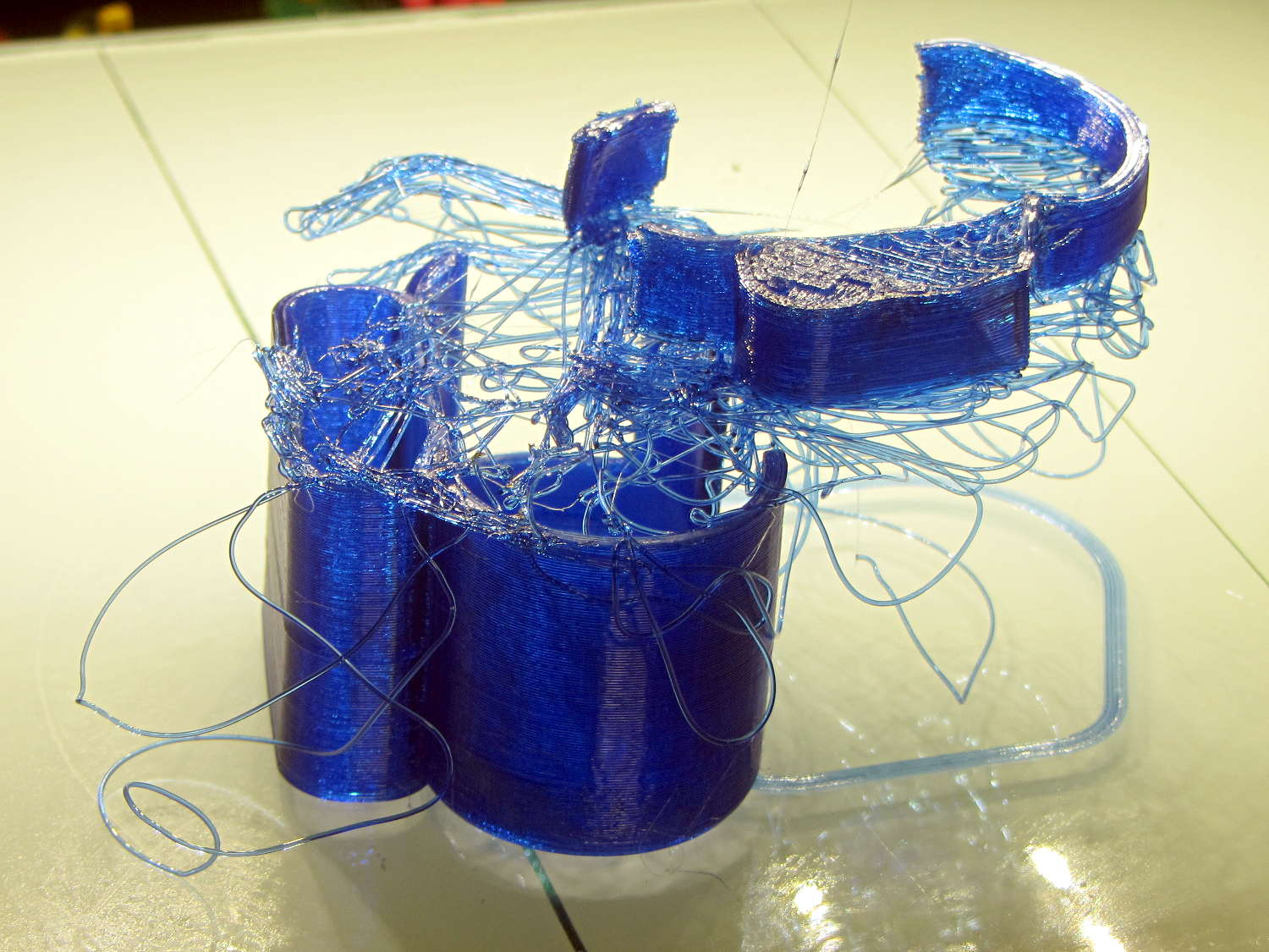
The mount isn’t designed for easy 3D printing, as it includes thin walls with chamfered edges, close tolerances, and aggressive bridging in dimension-critical areas. The first attempt failed when the minimal footprint (you’re looking at it in the picture above) pulled off the platform when the nozzle hit the lower bridge in the battery compartment:
Sony HDR-AS30V holder – failed print
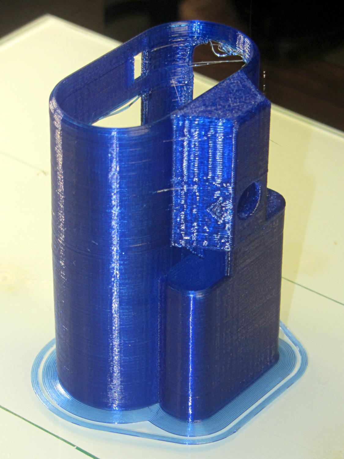
Surrounding the first layer with a 5 mm brim provided enough traction to finish the whole thing:
Sony HDR-AS30V holder – on platform
You can see some droopy threads across the openings; PETG bridges reasonably well, but the chamfers don’t provide good anchors. The opening for the camera hatch (on the far right rear) turned out slightly too short or, perhaps, the camera doesn’t seat quite far enough forward, which required some abrasive adjustment to accommodate the hatch.
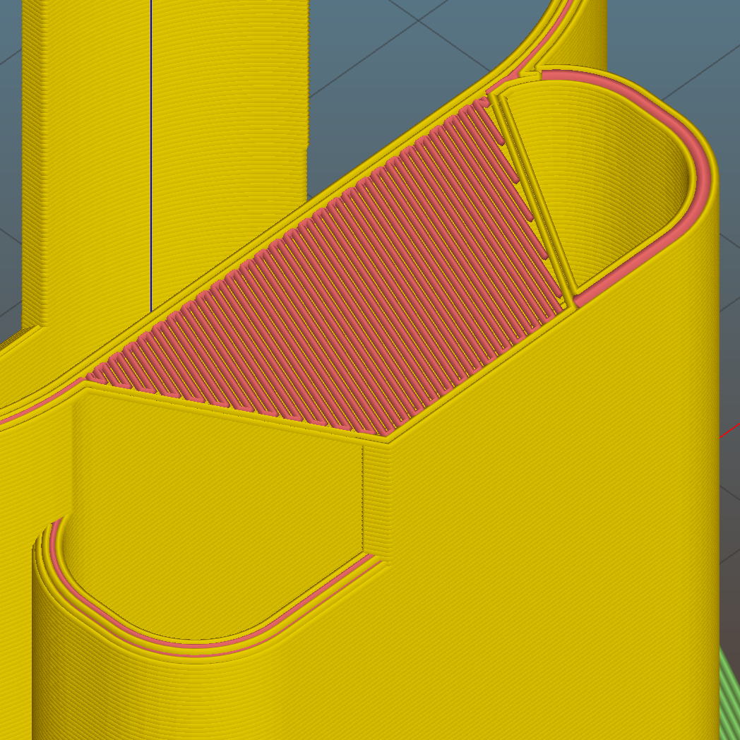
For unknown reasons, the top end of the battery compartment has a trapezoidal bridge:
Sony HDR-AS30V holder – trapezoidal bridge – Slic3r preview
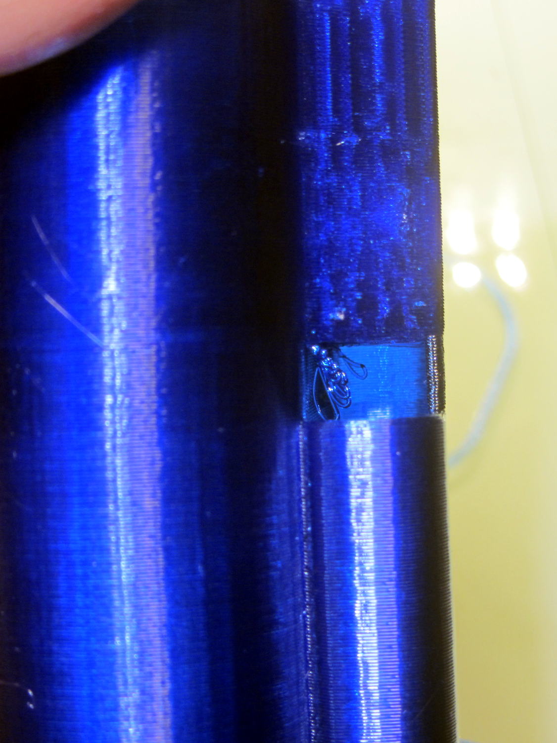
Which simply cannot be printed:
Sony HDR-AS30V holder – internal bridge failure
Cutting those threads out with an Xacto knife solved that problem.
The mount attaches to the tripod with a 1/4-20 nut trapped behind the hole next to the battery compartment. I grabbed an ordinary steel nut in a long normally closed tweezers, heated it over a butane lighter flame, threaded it onto a bolt stuck through the hole, and pulled it securely into the trap with exactly zero drama.
It has a very, very snug fit around the camera and battery that’s much better than a loose & floppy fit: there’s no positive retention latch.
This will serve as a prototype to see if the whole project works. If so, I’ll lash something together in OpenSCAD that should print a bit better, even if it looks like my usual brackets…