Ed Nisley's Blog: Shop notes, electronics, firmware, machinery, 3D printing, laser cuttery, and curiosities. Contents: 100% human thinking, 0% AI slop.
A trio of N2O cartridges / capsules made their way into the Basement Laboratory and cried out to be fitted with fins:
N2O Capsule Fins – installed
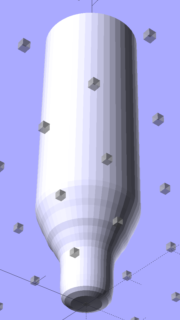
My original model tinkered up a cartridge from solid object primitives, but I’ve since discovered that cheating produces a much better and faster and easier result for cylindrical objects:
N2O Capsule – solid model – bottom view
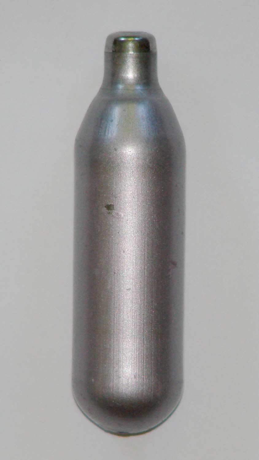
The trick is getting an image of the original object from the side, taken from far enough away to flatten the perspective:
N2O capsule – side view
Then overlay and scale a grid to match the actual length:
N2O capsule – grid overlay
The grid has 1 mm per minor square, centered along the cartridge’s axis, and zeroed at the tip; I rotated the cartridge image by half a degree to line it up with the grid.
Print it out on actual paper so you can eyeball the measurements and write ’em where you need ’em:
N2O capsule – grid overlay – printed
Which becomes an OpenSCAD polygon definition:
RADIUS = 0;				// subscript for radius values
HEIGHT = 1;				//   ... height above Z=0 at seal flange

//-- N2O 8 g capsule

CartridgeOutline = [			// X values = measured radius, Y as distance from tip
	[0.0,0.0],					//  0 cartridge seal tip
	[2.5,0.1],					//  1 seal disk
	[3.5,0.5],[4.0,1.0],		//  2 tip end
	[4.2,2.0],[4.3,3.0],		//  4 tip
	[4.3,6.0],					//  6 chamfer
	[4.5,8.0],					//  7 taper
	[4.9,9.0],					//  8
	[5.5,10.0],					//  9
	[6.0,11.0],					// 10
	[6.7,12.0],					// 11
	[7.1,13.0],					// 12
	[7.5,14.0],					// 13
	[8.0,15.0],					// 14
	[8.4,16.0],					// 15
	[8.8,17.0],					// 16
	[9.0,18.0],[9.0,58.0],		// 17 body
	[0.0,65.0]					// 19 dummy end cone
	];

TipLength = CartridgeOutline[6][HEIGHT];
TipOD = 2*CartridgeOutline[5][RADIUS];

BodyOD = 2*CartridgeOutline[17][RADIUS];
BodyOAL = CartridgeOutline[19][HEIGHT];
Because the rounded end of the cartridge doesn’t matter, I turned it into a cone.
Which then punches a matching dent in the fin structure:
Gas Capsule Fins – Slic3r preview
The lead picture doesn’t quite match the Slic3r preview, as I found the single-width diagonal fins weren’t strong enough. Making them two (nominal) threads wide lets Slic3r lay down three thinner threads in the same space:
Gas Capsule Fins – thicker – Slic3r preview
That’s letting Slic3r automagically determine the infill and perimeter thread width to make the answer come out right. As nearly as I can tell, the slicing algorithms have become smart enough to get the right answer nearly all of the time, so I can-and-should relinquish more control over the details.
The OpenSCAD source code:
// CO2 capsule tail fins
// Ed Nisley KE4ZNU - October 2015
Layout = "Build"; // Show Build FinBlock Cartridge Fit
//-------
//- Extrusion parameters must match reality!
// Print with +0 shells and 3 solid layers
ThreadThick = 0.25;
ThreadWidth = 0.40;
HoleWindage = 0.2;
Protrusion = 0.1; // make holes end cleanly
function IntegerMultiple(Size,Unit) = Unit * ceil(Size / Unit);
//-------
// Capsule dimensions
CartridgeSides = 12*4; // number of sides
RADIUS = 0; // subscript for radius values
HEIGHT = 1; // ... height above Z=0 at seal flange
//-- N2O 8 g capsule
RW = HoleWindage/2; // enlarge radius by just enough
CartridgeOutline = [ // X values = measured radius, Y as distance from tip
[0.0,0.0], // 0 cartridge seal tip
[2.5 + RW,0.1], // 1 seal disk
[3.5 + RW,0.5],[4.0 + RW,1.0], // 2 tip end
[4.2 + RW,2.0],[4.3 + RW,3.0], // 4 tip
[4.3 + RW,6.0], // 6 chamfer
[4.5 + RW,8.0], // 7 taper
[4.9 + RW,9.0], // 8
[5.5 + RW,10.0], // 9
[6.0 + RW,11.0], // 10
[6.7 + RW,12.0], // 11
[7.1 + RW,13.0], // 12
[7.5 + RW,14.0], // 13
[8.0 + RW,15.0], // 14
[8.4 + RW,16.0], // 15
[8.8 + RW,17.0], // 16
[9.0 + RW,18.0],[9.0 + RW,58.0], // 17 body
[0.0,65.0] // 19 dummy end cone
];
TipLength = CartridgeOutline[6][HEIGHT];
TipOD = 2*CartridgeOutline[5][RADIUS];
CylinderBase = CartridgeOutline[17][HEIGHT];
BodyOD = 2*CartridgeOutline[17][RADIUS];
BodyOAL = CartridgeOutline[19][HEIGHT];
//-------
// Fin dimensions
FinThick = 1.5*ThreadWidth; // outer square
StrutThick = 2.0*ThreadWidth; // diagonal struts
FinSquare = 1.25*BodyOD;
FinTaperLength = sqrt(2)*FinSquare/2 - sqrt(2)*FinThick - ThreadWidth;
FinBaseLength = 0.7 * CylinderBase;
FinTop = 0.9*CylinderBase;
//-------
module PolyCyl(Dia,Height,ForceSides=0) { // based on nophead's polyholes
Sides = (ForceSides != 0) ? ForceSides : (ceil(Dia) + 2);
FixDia = Dia / cos(180/Sides);
cylinder(r=(FixDia + HoleWindage)/2,h=Height,$fn=Sides);
}
module ShowPegGrid(Space = 10.0,Size = 1.0) {
Range = floor(50 / Space);
for (x=[-Range:Range])
for (y=[-Range:Range])
translate([x*Space,y*Space,Size/2])
%cube(Size,center=true);
}
//-------
// CO2 cartridge outline
module Cartridge() {

 rotate_extrude($fn=CartridgeSides)
 polygon(points=CartridgeOutline);

}
//-------
// Diagonal fin strut
module FinStrut() {
intersection() {
rotate([90,0,45])
translate([0,0,-StrutThick/2])
linear_extrude(height=StrutThick)
polygon(points=[
[0,0],
[FinTaperLength,0],
[FinTaperLength,FinBaseLength],
[0,(FinBaseLength + FinTaperLength)]
]);
translate([0,0,FinTop/2])
cube([2*FinSquare,2*FinSquare,FinTop], center=true);
}
}
//-------
// Fin outline
module FinBlock() {
$fn=12;
render(convexity = 4)
union() {
translate([0,0,FinBaseLength/2])
difference() {
intersection() {
minkowski() {
cube([FinSquare - 2*ThreadWidth,
FinSquare - 2*ThreadWidth,
FinBaseLength],center=true);
cylinder(r=FinThick,h=Protrusion,$fn=8);
}
cube([2*FinSquare,2*FinSquare,FinBaseLength],center=true);
}
difference() {
cube([(FinSquare - 2*FinThick),
(FinSquare - 2*FinThick),
(FinBaseLength + 2*Protrusion)],center=true);
for (Index = [0:3])
rotate(Index*90)
translate([(FinSquare/2 - FinThick),(FinSquare/2 - FinThick),0])
cylinder(r=2*StrutThick,h=(FinBaseLength + 2*Protrusion),center=true,$fn=16);
}
}
for (Index = [0:3])
rotate(Index*90)
FinStrut();
rotate(180/12)
cylinder(d=IntegerMultiple(TipOD + 6*ThreadWidth,ThreadWidth),h=TipLength);
}
}
//-------
// Fins
module FinAssembly() {
difference() {
FinBlock();
translate([0,0,2*ThreadThick]) // add two layers to close base cylinder
Cartridge();
}
}
module FinFit() {
translate([0,0.75*BodyBaseLength,2*ThreadThick])
rotate([90,0,0])
difference() {
translate([-FinSquare/2,-2*ThreadThick,0])
cube([IntegerMultiple(FinSquare,ThreadWidth),
4*ThreadThick,
1.5*BodyBaseLength]);
translate([0,0,5*ThreadWidth])
Cartridge();
}
}
//-------
// Build it!
ShowPegGrid();
if (Layout == "FinStrut")
FinStrut();
if (Layout == "FinBlock")
FinBlock();
if (Layout == "Cartridge")
Cartridge();
if (Layout == "Show") {
FinAssembly();
color("LightYellow") Cartridge();
}
if (Layout == "Fit")
FinFit();
if (Layout == "Build")
FinAssembly();
It took a while, but the owners of Janet Drive did a commendable job of resurfacing the giant potholes that were consuming the parking lot entrance:
Janet Dr at 708 Dutchess Turnpike entrance – 2015-10-05
That patch covers all the holes, has a smooth surface, and neatly joins the adjacent pavement without huge bumps. It’s entirely possible to do good repairs, if you just hire the right contractor.
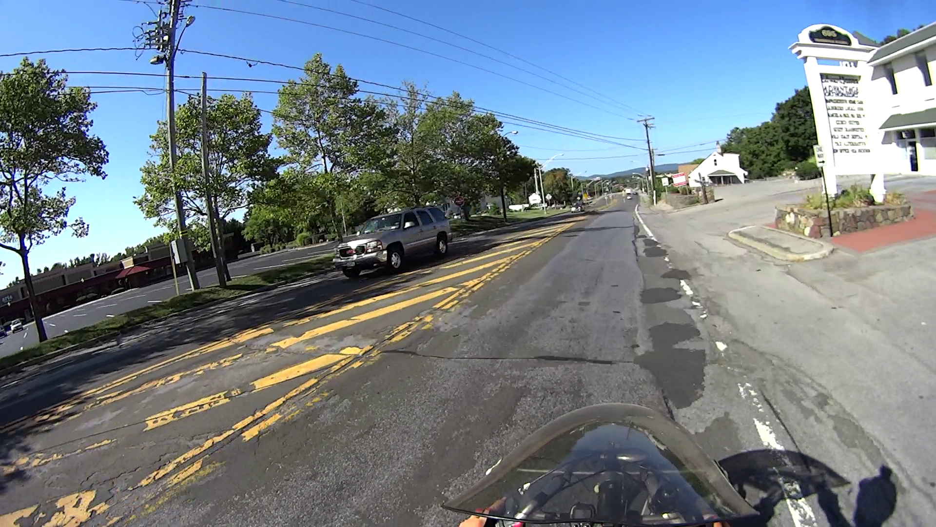
Which doesn’t happen if you’re NYSDOT, unfortunately, as they regards a few random hand-tamped blobs on a section of Rt 44 (and Bike Rt 44, for whatever that’s worth) as entirely adequate:
Rt 44 – 695 at Quest Diagnostics – 2015-10-05 – no progress
The sinkhole on Rt 376 that we must dodge maybe four times every week continues to grow:
Somebody who should know better suggested the NYSDOT crew just ran out of asphalt after patching all around the sinkhole that I’d reported back in July, but …
The NYSDOT Bicycle and Pedestrian Coordinator (yeah, she exists) assured me the engineers were studying the signal timing and would contact me directly:
Burnett at Rt 55 2015-08-31 – Yellow 8 s after green with cars
That hasn’t happened after four months, so I’d say NYSDOT uses the word “study” to mean “stonewall”.
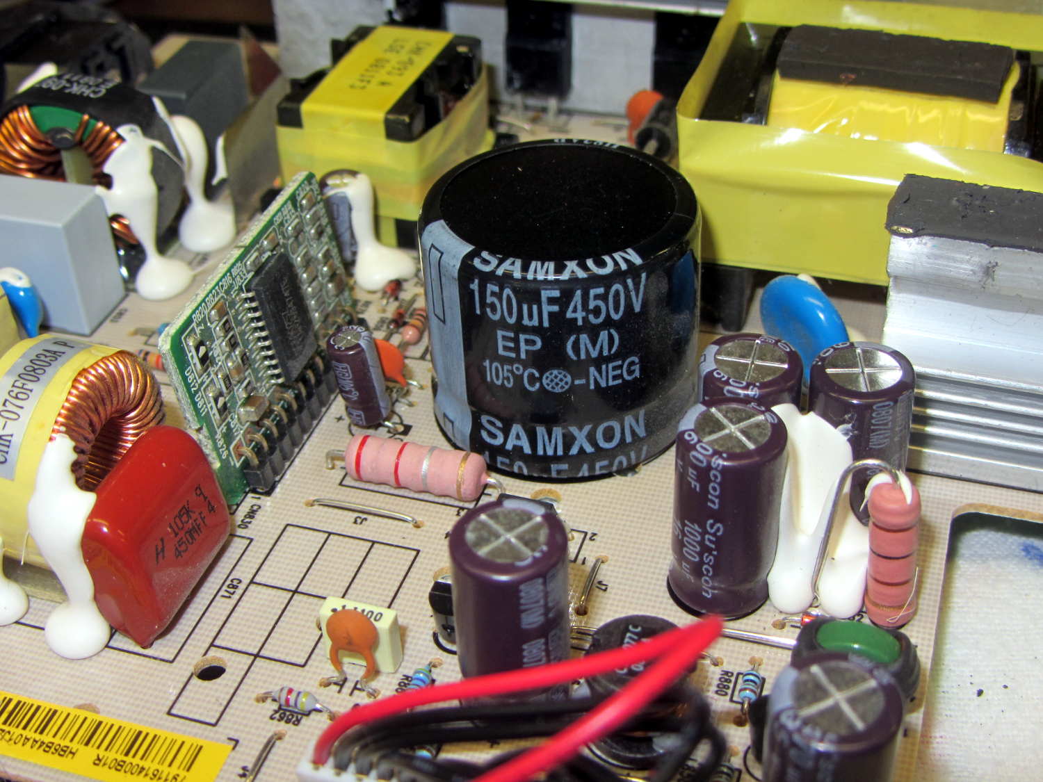
Quite some time ago, I picked up a nice monitor that turned out to be a debranded (all OEM labels removed or covered) HP w2408. It eventually became erratic, refusing to turn on or return from power-save mode, so I took it apart. All the caps looked good and seemed to have low ESR, except for the big one in the middle of the power supply board:
HP 2408 monitor power supply – HV cap
It’s 30 mm in diameter, with 10 mm lead spacing, and stands a squat 26 mm tall, ignoring a millimeter or two of bulge in its should-be-flat black cap:
HP 2408 monitor power supply – HV cap bulge
Having never seen one of that size before, I sent a note and picture to folks who sell re-capping kits for monitors, in the hope that they’ll have a lead.
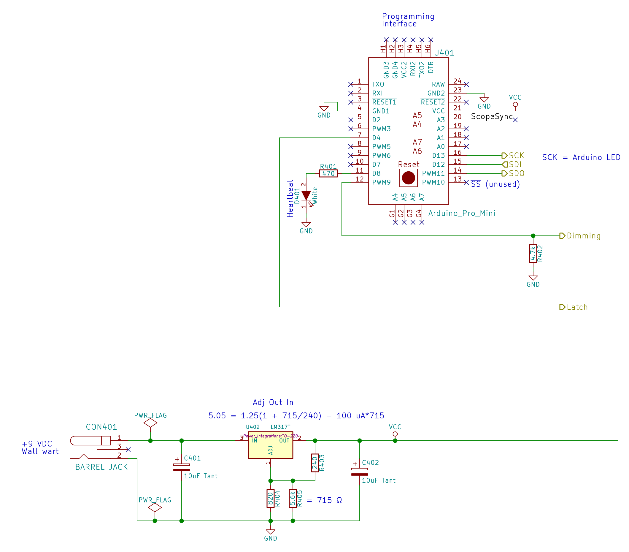
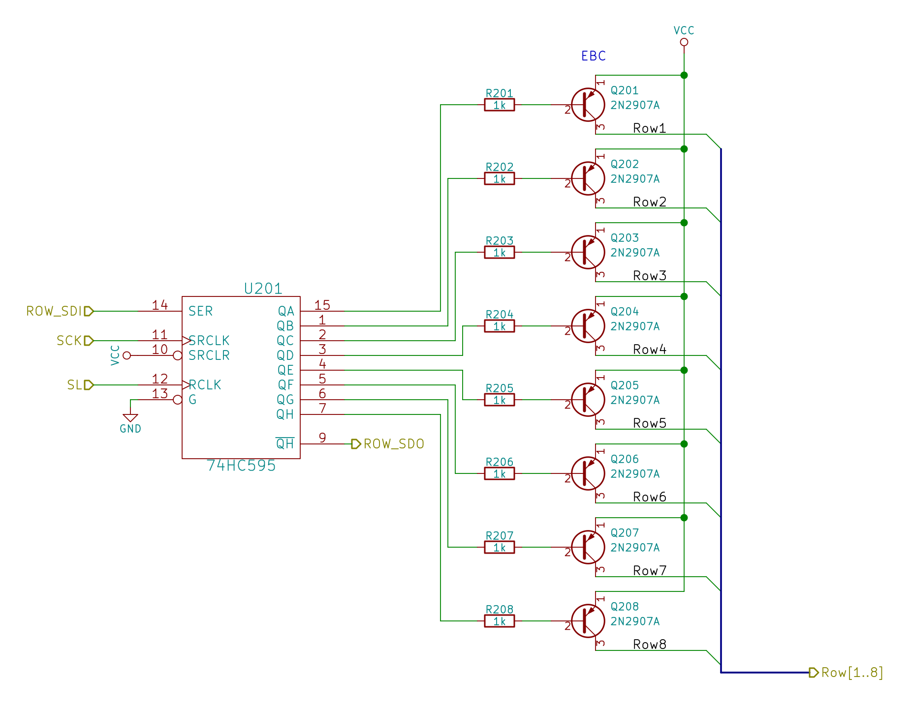
// Random LED Dots - from noise source
// Ed Nisley - KE4ANU - September 2015

//----------
// Pin assignments

const byte PIN_HEARTBEAT = 8;		// DO - heartbeat LED
const byte PIN_SYNC = A3;			// DO - scope sync

const byte PIN_LATCH  = 4;			// DO - shift register latch clock

const byte PIN_DIMMING = 9;			// AO - LED dimming control

// These are *hardware* SPI pins

const byte PIN_MOSI = 11;			// DO - data to shift reg
const byte PIN_MISO = 12;			// DI - data from shift reg - sampled noise input
const byte PIN_SCK  = 13;			// DO - shift clock to shift reg (also Arduino LED)
const byte PIN_SS = 10;				// DO - -slave select (must be positive for SPI output)

//----------
// Constants

#define DISPLAY_MS 10000ul

//----------
// Globals

// Input noise bits can produce one of four possible conditions
//  Use the von Neumann extractor, discarding 00 and 11 sequences
// https://en.wikipedia.org/wiki/Randomness_extractor#Von_Neumann_extractor
// Sampling interval depends on SPI data rate
// LSB arrives first, so it's the earliest sample

#define VNMASK_A 0x00000001
#define VNMASK_B 0x01000000

enum sample_t {VN_00,VN_01,VN_10,VN_11};

typedef struct {
	byte BitCount;					// number of bits accumulated so far
	unsigned Bits;					// random bits filled from low order upward
	int Bias;						// tallies 00 and 11 sequences to measure analog offset
   unsigned SampleCount[4];	// number of samples in each bin
} random_t;

random_t RandomData;

// LED selects are high-active bits and low-active signals: flipped in UpdateLEDs()
// *exactly* one row select must be active in each element

typedef struct {
	const byte Row;
	byte ColR;
	byte ColG;
	byte ColB;
} leds_t;

// altering the number of rows & columns will require substantial code changes...
#define NUMROWS 8
#define NUMCOLS 8

leds_t LEDs[NUMROWS] = {
	{0x80,0,0,0},
	{0x40,0,0,0},
	{0x20,0,0,0},
	{0x10,0,0,0},
	{0x08,0,0,0},
	{0x04,0,0,0},
	{0x02,0,0,0},
	{0x01,0,0,0},
};

byte RowIndex;

#define LEDS_ON 0
#define LEDS_OFF 255

unsigned long MillisNow;
unsigned long DisplayBase;

//-- Helper routine for printf()

int s_putc(char c, FILE *t) {
  Serial.write(c);
}

//-- Useful stuff

// Free RAM space monitor
//  From http://playground.arduino.cc/Code/AvailableMemory

uint8_t * heapptr, * stackptr;

void check_mem() {
  stackptr = (uint8_t *)malloc(4);          // use stackptr temporarily
  heapptr = stackptr;                     // save value of heap pointer
  free(stackptr);      // free up the memory again (sets stackptr to 0)
  stackptr =  (uint8_t *)(SP);           // save value of stack pointer
}

void TogglePin(char bitpin) {
	digitalWrite(bitpin,!digitalRead(bitpin));    // toggle the bit based on previous output
}

void PulsePin(char bitpin) {
	TogglePin(bitpin);
	TogglePin(bitpin);
}

//---------
//-- SPI utilities

void EnableSPI(void) {
	digitalWrite(PIN_SS,HIGH);					// make sure this is high!
	SPCR |= 1 << SPE;
}

void DisableSPI(void) {
	SPCR &= ~(1 << SPE);
}

void WaitSPIF(void) {
	while (! (SPSR & (1 << SPIF))) {
//		TogglePin(PIN_HEARTBEAT);
		continue;
	}
}

byte SendRecSPI(byte DataByte) {					// send one byte, get another in exchange
	SPDR = DataByte;
	WaitSPIF();
	return SPDR;									// SPIF will be cleared
}

//---------------
// Update LED shift registers with new data
// Returns noise data shifted in through MISO bit

unsigned long UpdateLEDs(byte i) {

unsigned long NoiseData = 0ul;

	NoiseData |= (unsigned long) SendRecSPI(~LEDs[i].ColB);				// correct for low-active outputs
	NoiseData |= ((unsigned long) SendRecSPI(~LEDs[i].ColG)) << 8;
	NoiseData |= ((unsigned long) SendRecSPI(~LEDs[i].ColR)) << 16;
	NoiseData |= ((unsigned long) SendRecSPI(~LEDs[i].Row))  << 24;

	analogWrite(PIN_DIMMING,LEDS_OFF);			// turn off LED to quench current
	PulsePin(PIN_LATCH);						// make new shift reg contents visible
	analogWrite(PIN_DIMMING,LEDS_ON);

	return NoiseData;
}

//---------------
// Extract random data from sampled noise input
//  ... tuck it into the global bit structure
// Returns von Neumann status of the sample

byte ExtractRandomBit(unsigned long RawSample) {

byte RetVal;

	switch (RawSample & (VNMASK_A | VNMASK_B)) {
	case 0:							// 00 - discard
		RetVal = VN_00;
		RandomData.Bias--;
		break;
	case VNMASK_A:					// 10 - true
		RetVal = VN_10;
		RandomData.BitCount++;
		RandomData.Bits = (RandomData.Bits << 1) | 1;
		break;
	case VNMASK_B:					// 01 - false
		RetVal = VN_01;
		RandomData.BitCount++;
		RandomData.Bits  = RandomData.Bits << 1;
		break;
	case (VNMASK_A | VNMASK_B):		// 11 - discard
		RetVal = VN_11;
		RandomData.Bias++;
		break;
	}

	RandomData.Bias = constrain(RandomData.Bias,-9999,9999);
	RandomData.SampleCount[RetVal]++;
	RandomData.SampleCount[RetVal] = constrain(RandomData.SampleCount[RetVal],0,63999);

	return RetVal;
}

//---------------
// Set LED from random bits
// Assumes the Value contains at least nine low-order random bits
// On average, this leaves the LED unchanged for 1/8 of the calls...

void SetLED(unsigned Value) {

byte Row =   Value        & 0x07;
byte Col =   (Value >> 3) & 0x07;
byte Color = (Value >> 6) & 0x07;

byte BitMask = (0x80 >> Col);

//	printf("%u %u %u %u\r\n",Row,Col,Color,BitMask);

	LEDs[Row].ColR &= ~BitMask;
	LEDs[Row].ColR |= (Color & 0x04) ? BitMask : 0;

	LEDs[Row].ColG &= ~BitMask;
	LEDs[Row].ColG |= (Color & 0x02) ? BitMask : 0;

	LEDs[Row].ColB &= ~BitMask;
	LEDs[Row].ColB |= (Color & 0x01) ? BitMask : 0;

}

//------------------
// Set things up

void setup() {

	pinMode(PIN_HEARTBEAT,OUTPUT);
	digitalWrite(PIN_HEARTBEAT,HIGH);		// show we arrived

	pinMode(PIN_SYNC,OUTPUT);
	digitalWrite(PIN_SYNC,LOW);

	pinMode(PIN_MOSI,OUTPUT);				// SPI-as-output is not strictly necessary
	digitalWrite(PIN_MOSI,LOW);

	pinMode(PIN_SCK,OUTPUT);
	digitalWrite(PIN_SCK,LOW);

	pinMode(PIN_SS,OUTPUT);
	digitalWrite(PIN_SS,HIGH);				// OUTPUT + HIGH is required to make SPI output work

	pinMode(PIN_LATCH,OUTPUT);
	digitalWrite(PIN_LATCH,LOW);

	Serial.begin(57600);
	fdevopen(&s_putc,0);					// set up serial output for printf()

	printf("Noisy LED Dots\r\nEd Nisley - KE4ZNU - September 2015\r\n");

//-- Set up SPI hardware
// LSB of SPCR set bit clock speed:
//  00 = f/4
//  01 = f/16
//  10 = f/64
//  11 = f/128

	SPCR = B01110011;						// Auto SPI: no int, enable, LSB first, master, + edge, leading, speed
	SPSR = B00000000;						// not double data rate

	EnableSPI();							// turn on the SPI hardware

	SendRecSPI(0);							// set valid data in shift registers: select Row 0, all LEDs off

//-- Dimming pin must use fast PWM to avoid beat flicker with LED refresh rate
//   Timer 1: PWM 9 PWM 10

	analogWrite(PIN_DIMMING,LEDS_OFF);		// disable column drive (hardware pulled it low before startup)

	TCCR1A = B10000001; 					// Mode 5 = fast 8-bit PWM with TOP=FF
	TCCR1B = B00001001; 					// ... WGM, 1:1 clock scale -> 64 kHz

//-- lamp test: send a white flash through all LEDs
//	 collects noise data to get some randomness going

	printf("Lamp test begins: white flash each LED...");

	digitalWrite(PIN_HEARTBEAT,LOW);		// turn off while panel blinks

	analogWrite(PIN_DIMMING,LEDS_ON);		// enable column drive

	for (byte i=0; i<NUMROWS; i++) {
		for (byte j=0; j<NUMCOLS; j++) {
			LEDs[i].ColR = LEDs[i].ColG = LEDs[i].ColB = 0x80 >> j;
			for (byte k=0; k<NUMROWS; k++) {
				ExtractRandomBit(UpdateLEDs(k));
				delay(25);
			}
		LEDs[i].ColR = LEDs[i].ColG = LEDs[i].ColB = 0;
		}
	}
	UpdateLEDs(NUMROWS-1);					// clear the last LED

	printf(" done!\r\n");

//-- Preload LEDs with random values
//   We take whatever number of random bits arrived in RandomData during lamp test

	digitalWrite(PIN_HEARTBEAT,LOW);
	printf("Preloading LED array\r\nRandom bits %04x\r\n",RandomData.Bits);

	randomSeed(RandomData.Bits);

	for (byte Row=0; Row<NUMROWS; Row++) {
		for (byte Col=0; Col<NUMCOLS; Col++) {		// Col runs backwards, but we don't care
			LEDs[Row].ColR |= random(2) << Col;
			LEDs[Row].ColG |= random(2) << Col;
			LEDs[Row].ColB |= random(2) << Col;
		}
		UpdateLEDs(Row);
	}

	RandomData.BitCount = 0;
	RandomData.Bits = 0;
	RandomData.Bias = 0;
   for (byte i=0; i<4; i++) {
	   RandomData.SampleCount[i] = 0;
   }

	check_mem();
	printf("SP: %u HP: %u Free RAM: %u\r\n",stackptr,heapptr,stackptr - heapptr);

	printf("Running...\r\n");

	DisplayBase = millis();

}

//------------------
// Run the test loop

void loop() {

byte ThisBit;

	MillisNow = millis();

	if (RowIndex >= NUMROWS) {							// set up LED row index for this pass
		RowIndex = 0;
		PulsePin(PIN_SYNC);
	}

	if ((MillisNow - DisplayBase) >= DISPLAY_MS) {
		analogWrite(PIN_DIMMING,LEDS_OFF);				// turn off LED to prevent bright glitch
		printf("Bias: %5d of %5u - %5u %5u %5u %5u\r\n",
         RandomData.Bias,
         RandomData.SampleCount[VN_00] + RandomData.SampleCount[VN_11],
         RandomData.SampleCount[0],
         RandomData.SampleCount[1],
         RandomData.SampleCount[2],
         RandomData.SampleCount[3]
         );
		RandomData.Bias = 0;
      for (byte i=0; i<4; i++) {
         RandomData.SampleCount[i] = 0;
      }
 //		check_mem();
//		printf("SP: %u HP: %u Free RAM: %u\r\n",stackptr,heapptr,stackptr - heapptr);
		DisplayBase = MillisNow;
	}

// Update one LED row per pass, get at most one random bit

	ThisBit = ExtractRandomBit(UpdateLEDs(RowIndex++));

// Update the heartbeat LED to show bit validity

	switch (ThisBit) {
		case VN_00:
		case VN_11:
			digitalWrite(PIN_HEARTBEAT,HIGH);
			break;
		case VN_01:
		case VN_10:
			digitalWrite(PIN_HEARTBEAT,LOW);
			break;
	}

// If we have enough random data, twiddle one LED

	if (RandomData.BitCount >= 9) {
//		analogWrite(PIN_DIMMING,LEDS_OFF);				// turn off LED array to prevent bright glitch

		SetLED(RandomData.Bits);
		RandomData.BitCount = 0;
		RandomData.Bits = 0;
	}

	digitalWrite(PIN_HEARTBEAT,LOW);

}
This orb weaving spider set up anchors on the patio, the railing, and the gutter, as have many before her, but managed to get a slight twist in her web:
Orb weaving spider – warped web
It seemed to work well, although she packed up and moved on after just one night.
We haven’t seen many orb spiders this year, for unknown reasons.