The Smell of Molten Projects in the Morning

Ed Nisley's Blog: Shop notes, electronics, firmware, machinery, 3D printing, laser cuttery, and curiosities. Contents: 100% human thinking, 0% AI slop.

Author: Ed

  • Epoxy-filled 3D Printed Characters

    Although Mary’s name in the base of the Clover Mini Iron holder was readable in person, I wondered what filling the characters with epoxy would do. A bit of tinkering produced a name plate:

    Text Block - solid model
    Text Block – solid model

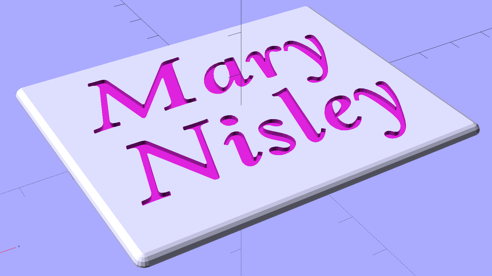
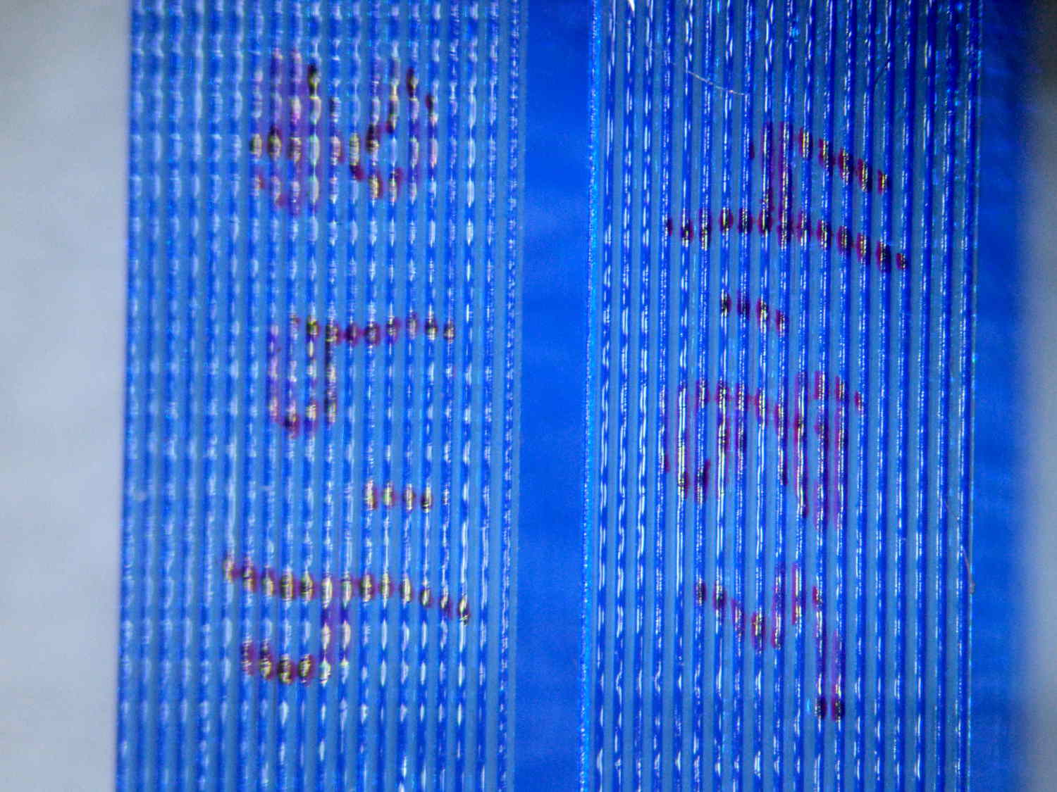
    Which is more readable in person, but magenta PETG renders it basically unreadable here:

    Text Block - unfilled
    Text Block – unfilled

    The intent of this was not to produce a lovely name block, but to see what various epoxy fills and techniques produced. Think of this as the one you must build to throw away…

    I tediously filled the first line with straight JB Weld epoxy, deliberately ruining the least functional of my 1 ml syringes to ease a strand of epoxy into each letter, then poking the goo into place with a pointed rod:

    Text Block - plain epoxy fill
    Text Block – plain epoxy fill

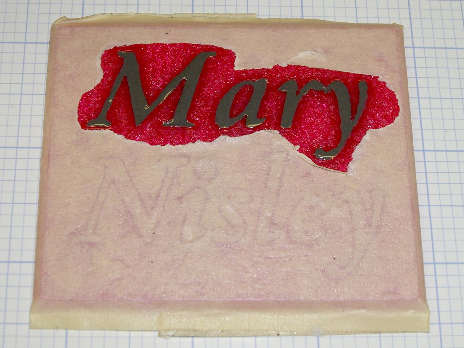
    That was way tedious.

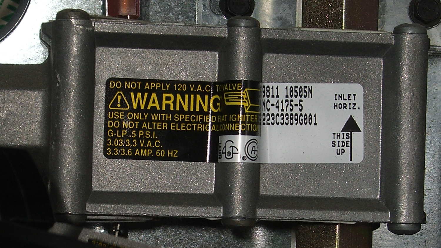
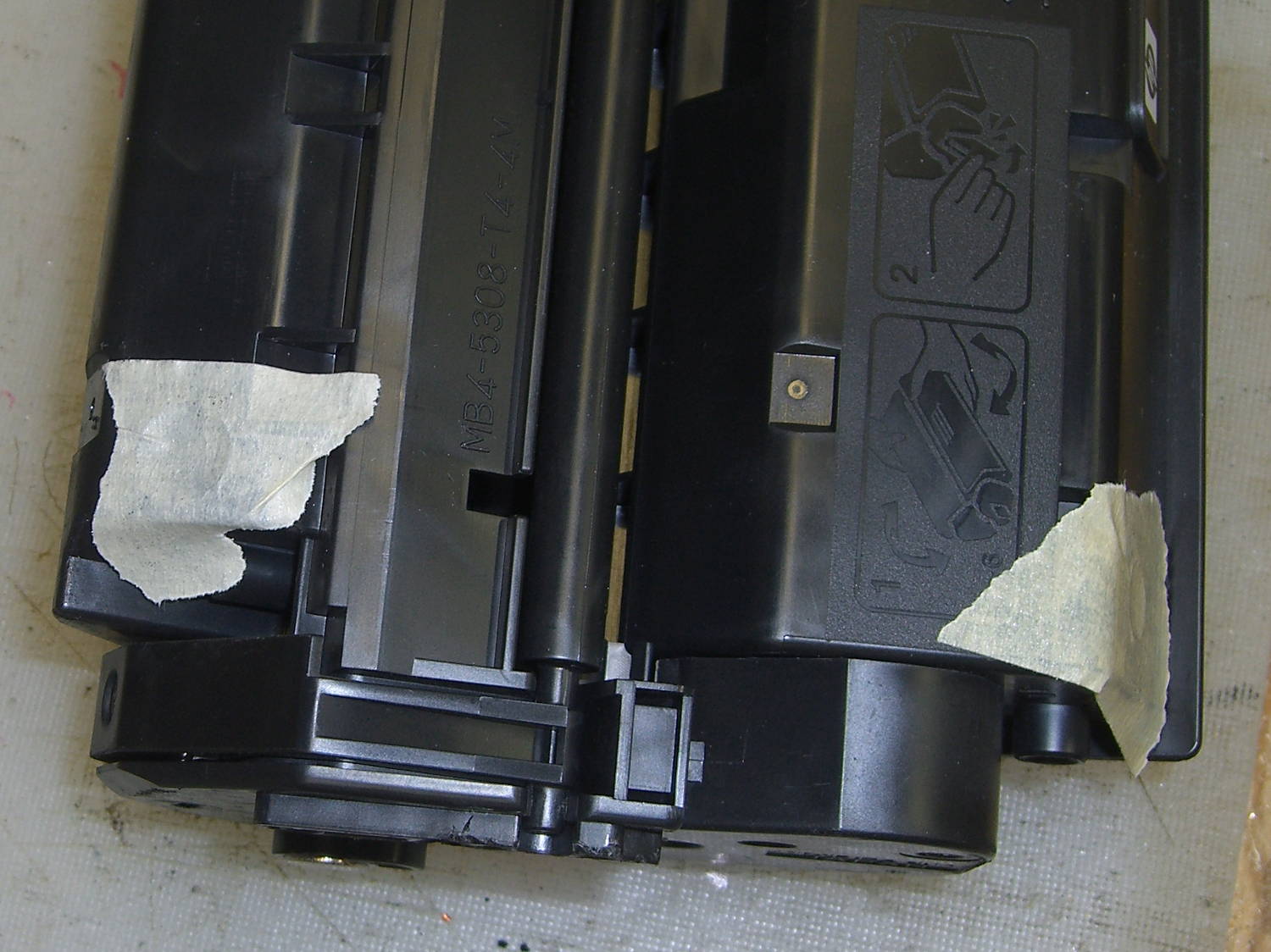
    Having recently replaced the cartridge in our trusty HP Laserjet 1200, I had no qualms about step-drilling the “empty” cartridge to get the toner. For future reference, here’s where you drill into a 7115X cartridge:

    HP 7115X Toner Cartridge - holes in waste and supply compartments
    HP 7115X Toner Cartridge – holes in waste and supply compartments

    I probably used too much toner, but one heaping pile on that wooden stick didn’t seem like a lot at the time:

    Text Block - toner black epoxy
    Text Block – toner black epoxy

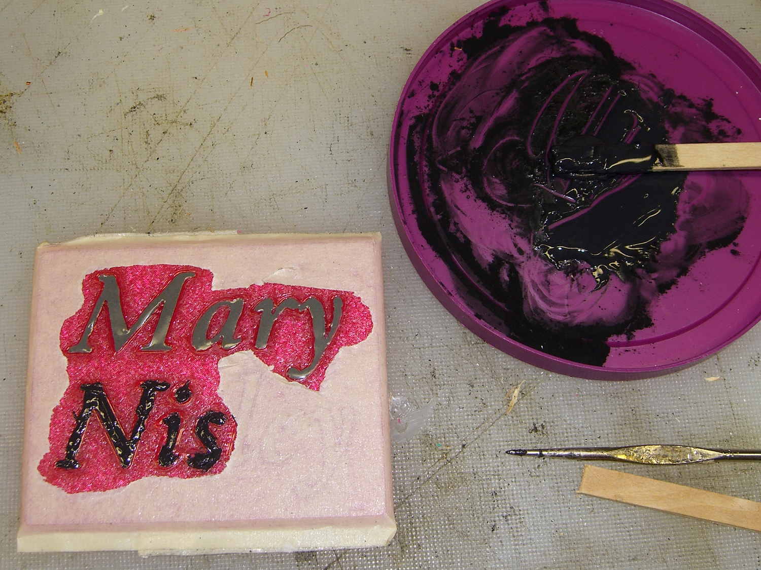
    This turned the epoxy rather thick and pasty; it didn’t ease into the letters very well at all. After the usual day, it cured into a slightly rubbery solid, quite unlike the usual rock-solid epoxy blob.

    Some rummaging in the Basement Laboratory Warehouse Wing turned up two containers of aluminum powder from an Etch-a-Sketch; I mixed some into another batch of epoxy, to very little effect. With both blends, I just squished the epoxy into the letters and didn’t worry too much about slobbering any over the surface of the block.

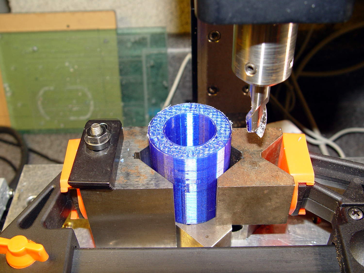
    To even off the top surface, I affixed the block to the Sherline’s tooling plate with tapeless sticky (basically double-sided tape without the tape):

    Text Block - milling setup
    Text Block – milling setup

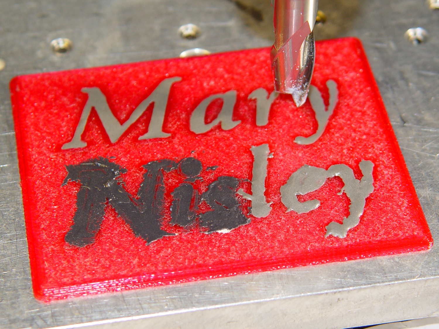
    Manually traversing the surface (3 k rpm, 24 inch/min) and stepping downward about 0.1 mm per pass gradually crisped up the letters. I expected the excess epoxy to vanish after going 0.1 mm or so into the top layer, but it actually required removing the entire 0.25 mm Hilbert-curve-filled surface layer to get rid of the epoxy that soaked into / through the tiny gaps. This is 0.4 mm down from the first pass, maybe 0.1 mm into the plastic:

    Text Block - milled 0.4 mm
    Text Block – milled 0.4 mm

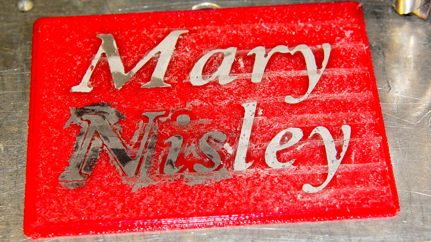
    With the top layer gone, it looked rather gnarly, so I applied a sanding block that didn’t do much at all: smoother, still gnarly. Spreading maybe 0.3 ml of IPS 4 solvent adhesive over the sanded surface smoothed it a bit:

    Text Block - sanded and leveled with IPS 4
    Text Block – sanded and leveled with IPS 4

    Perhaps a topcoat of clear epoxy, along the lines of XTC-3D, would produce better results.

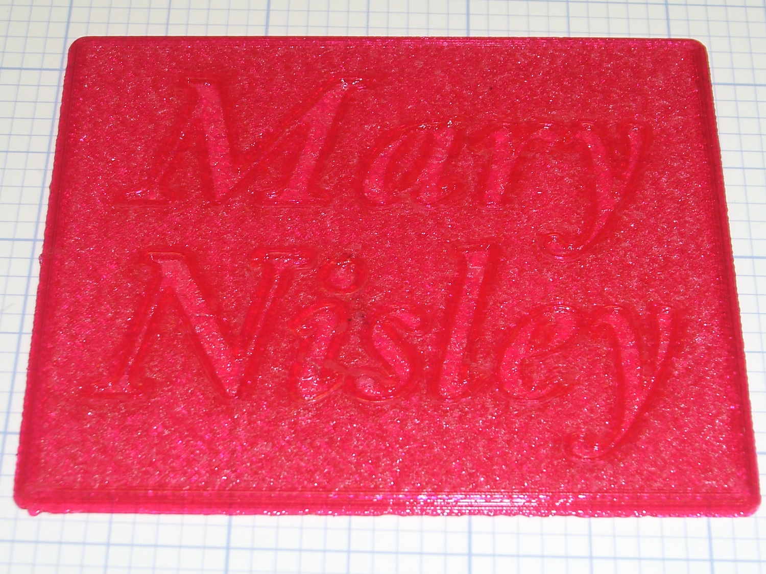
    The small black dots in the top line are holes from bubbles in the epoxy. The missing section of the M started out as a bubble (just visible at 0.4 mm) and gradually enlarged as pieces tore out of the recess. There’s another bubble breaking the right stroke of the “y”.

    The small dots in the “ley” are plastic spheres that carried the aluminum powder in the Etch-a-Sketch; they’re cross-sectioned and perfectly flat. The epoxy color is marginally lighter than the top line, but not enough to notice.

    Backlit on a window, nearly all of the ugly fades away:

    Text Block - backlit
    Text Block – backlit

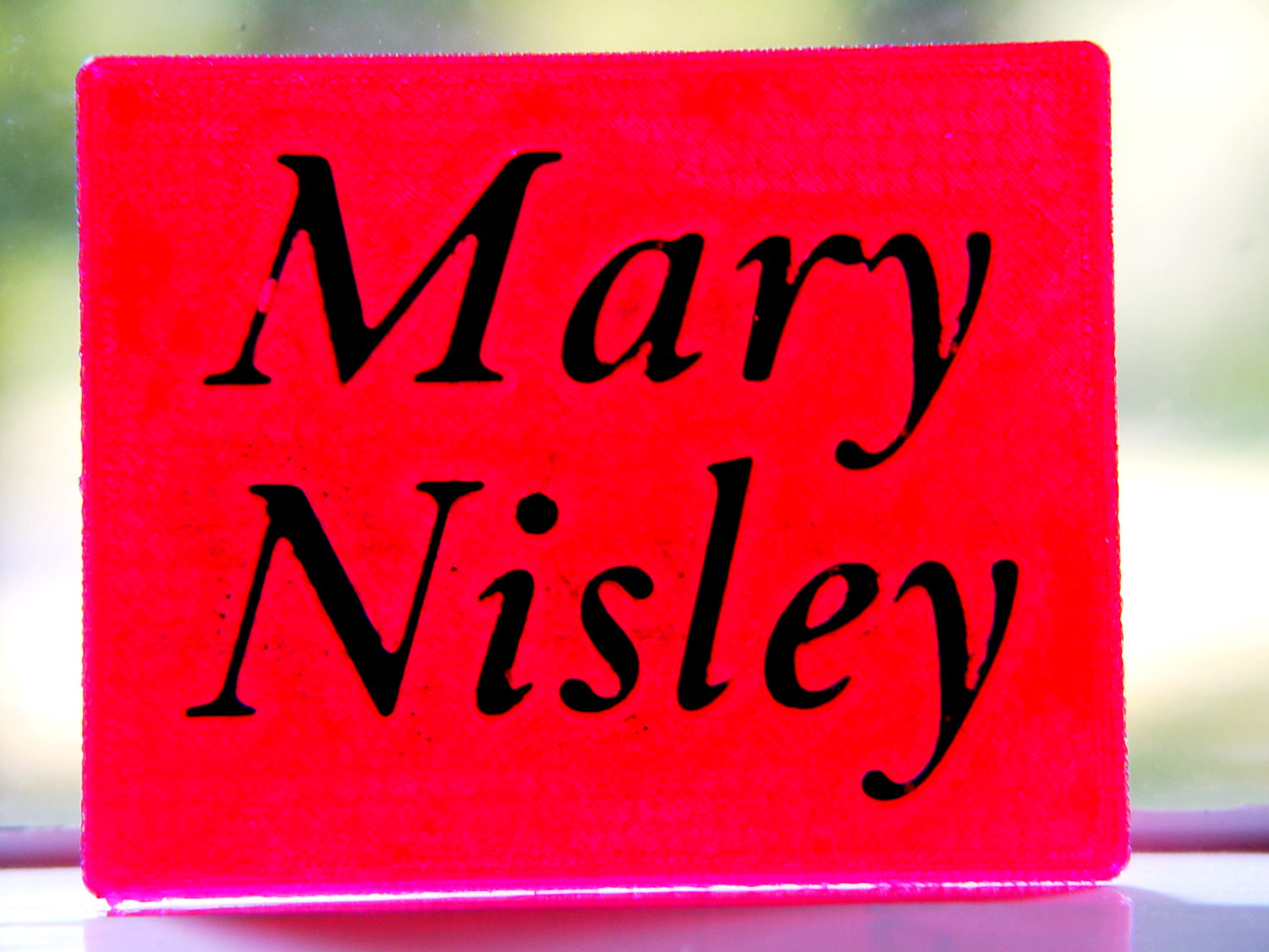
    It’s definitely not presentation quality, that’s for sure, and I won’t attempt to fill the Mini Iron holder…

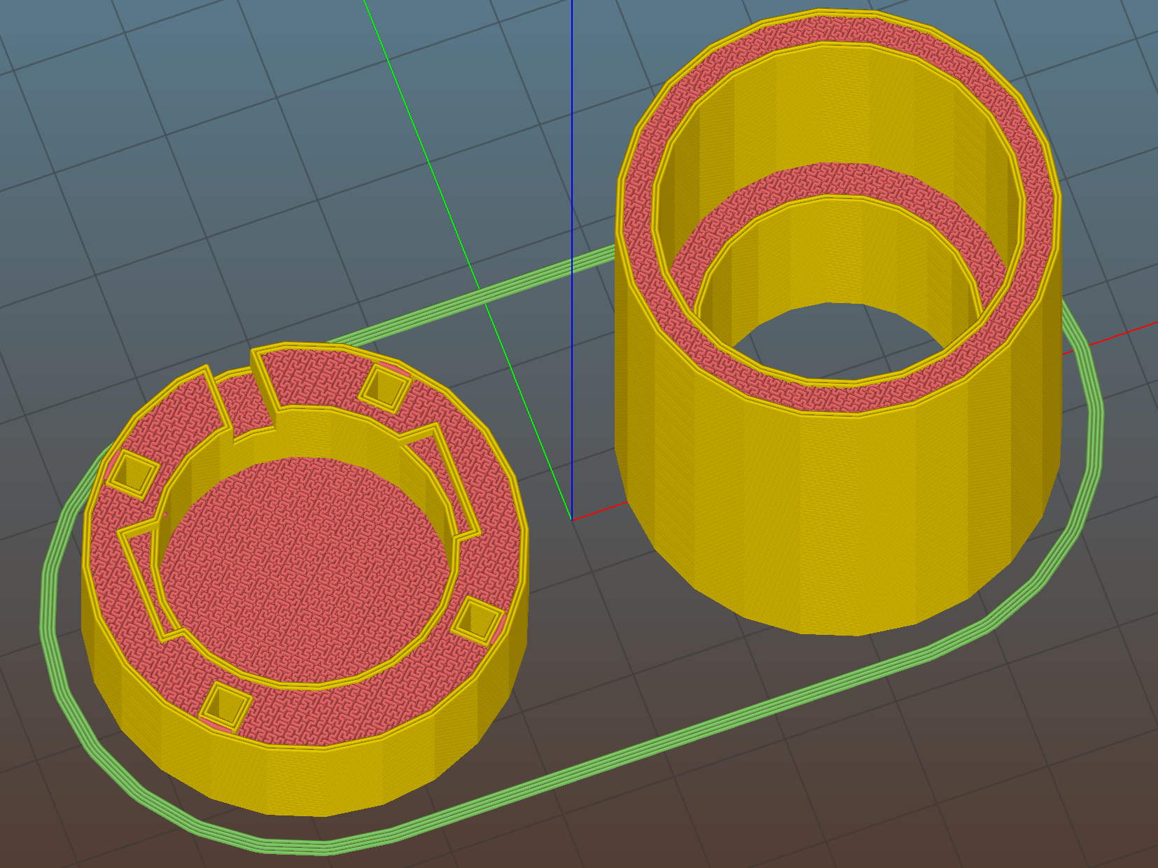
    The OpenSCAD source code, which can also produce the soldering iron holder:

    // Clover MCI-900 Mini Iron holder
    // Ed Nisley KE4ZNU - August 2015
    
    Layout = "Text";					// Iron Holder Show Text
    
    //- Extrusion parameters - must match reality!
    
    ThreadThick = 0.25;
    ThreadWidth = 0.40;
    
    function IntegerMultiple(Size,Unit) = Unit * ceil(Size / Unit);
    
    Protrusion = 0.1;
    
    HoleWindage = 0.2;
    
    inch = 25.4;
    
    Tap10_32 = 0.159 * inch;
    Clear10_32 = 0.190 * inch;
    Head10_32 = 0.373 * inch;
    Head10_32Thick = 0.110 * inch;
    Nut10_32Dia = 0.433 * inch;
    Nut10_32Thick = 0.130 * inch;
    Washer10_32OD = 0.381 * inch;
    Washer10_32ID = 0.204 * inch;
    
    //------
    // Dimensions
    
    CornerRadius = 4.0;
    
    CenterHeight = 25;							// center at cord inlet on body
    
    BodyLength = 110;							// cord inlet to body curve at front flange
    
    Incline = 10;								// central angle slope
    
    FrontOD = 29;
    FrontBlock = [20,1.5*FrontOD + 2*CornerRadius,FrontOD/2 + CenterHeight + BodyLength*sin(Incline)];
    
    CordOD = 10;
    CordLen = 10;
    
    RearOD = 22;
    RearBlock = [15 + CordLen,1.5*RearOD + 2*CornerRadius,RearOD/2 + CenterHeight];
    
    PlateWidth = 2*FrontBlock[1];
    
    TextDepth = 4*ThreadThick;
    
    ScrewOC = BodyLength - FrontBlock[0]/2;
    ScrewDepth = CenterHeight - FrontOD/2 - 5;
    
    echo(str("Screw OC: ",ScrewOC));
    
    BuildSize = [200,250,200];					// largest possible thing
    
    module PolyCyl(Dia,Height,ForceSides=0) {			// based on nophead's polyholes
    
      Sides = (ForceSides != 0) ? ForceSides : (ceil(Dia) + 2);
    
      FixDia = Dia / cos(180/Sides);
    
      cylinder(r=(FixDia + HoleWindage)/2,
               h=Height,
    	   $fn=Sides);
    }
    
    // Trim bottom from child object
    
    module TrimBottom(BlockSize=BuildSize,Slice=CornerRadius) {
    	
    	intersection() {
    		translate([0,0,BlockSize[2]/2])
    			cube(BlockSize,center=true);
    		translate([0,0,-Slice])
    			children();
    	}
    }
    
    // Build a rounded block-like thing
    
    module RoundBlock(Size=[20,25,30],Radius=CornerRadius,Center=false) {
    	
    	HS = Size/2 - [Radius,Radius,Radius];
    	translate([0,0,Center ? 0 : (HS[2] + Radius)])
    	hull() {
    		for (i=[-1,1], j=[-1,1], k=[-1,1]) {
    			translate([i*HS[0],j*HS[1],k*HS[2]])
    				sphere(r=Radius,$fn=4*4);
    		}
    	}
    }
    
    // Create a channel to hold something
    // This will eventually be subtracted from a block
    // The offsets are specialized for this application...
    
    module Channel(Dia,Length) {
    	
    	rotate([0,90,0])
    		linear_extrude(height=Length)
    			rotate(90)
    				hull() {
    					for (i=[-1,1])
    						translate([i*Dia,2*Dia])
    							circle(d=Dia/8);
    					circle(d=Dia,$fn=8*4);
    				}
    }
    
    // Iron-shaped series of channels to be removed from blocks
    
    module IronCutout() {
    
    	union() {
    		translate([-2*CordLen,0,0])
    			Channel(CordOD,2*CordLen + Protrusion);
    		Channel(RearOD,RearBlock[0] + Protrusion);
    		translate([BodyLength - FrontBlock[0]/2 - FrontBlock[0],0,0])
    			Channel(FrontOD,2*FrontBlock[0]);
    
    	}
    	
    }
    
    module TextBlock() {
    	translate([2,10,0])
    		linear_extrude(height=TextDepth + Protrusion,convexity=2)		// rendering glitches for convexity > 1
    //			text("Mary",font="Ubuntu:style=Bold Italic",halign="center",valign="center");
    			text("Mary",font="Junicode:style=Bold Italic",halign="center",valign="center",size=20,spacing=1.05);
    			
    	translate([2,-15,0])
    		linear_extrude(height=TextDepth + Protrusion,convexity=2)
    			text("Nisley",font="Junicode:style=Bold Italic",halign="center",valign="center",size=20,spacing=1.05);
    	
    }
    
    //- Build it
    
    if (Layout == "Iron")
    	IronCutout();
    
    if (Layout == "Holder" || Layout == "Show")
    	difference() {
    		union() {
    			translate([(BodyLength + CordLen)/2 - CordLen,0,0])
    				TrimBottom()
    					RoundBlock(Size=[(CordLen + BodyLength),PlateWidth,CornerRadius]);
    
    			translate([(RearBlock[0]/2 - CordLen),0,0])
    				TrimBottom()
    					RoundBlock(Size=RearBlock);
    
    			translate([BodyLength - FrontBlock[0]/2,0,0]) {
    				TrimBottom()
    					RoundBlock(Size=FrontBlock);
    			}
    		}
    		
    		translate([0,0,CenterHeight])
    			rotate([0,-Incline,0])
    				if (Layout == "Show")
    #					IronCutout();
    				else
    					IronCutout();
    		
    		translate([0,0,-Protrusion])
    			PolyCyl(Tap10_32,ScrewDepth + Protrusion,6);
    			
    		translate([ScrewOC,0,-Protrusion])
    			PolyCyl(Tap10_32,ScrewDepth + Protrusion,6);
    
    		translate([(RearBlock[0] - CordLen) + BodyLength/2 - FrontBlock[0],0,CornerRadius - TextDepth])
    			TextBlock();
    		
    	}
    	
    if (Layout == "Text")
    	difference() {
    		translate([0,0,0])
    			TrimBottom(Slice=8*ThreadThick)
    				RoundBlock(Size=[80,65,8*ThreadThick],Radius=8*ThreadThick);
    #		translate([-2,2,8*ThreadThick - TextDepth])
    			TextBlock();
    
    	}
    
  • HP 7475A Plotter: SuperFormula With Paper Size Sensing

    Well, it’s actually not “sensing”, but the demo code now sizes the graph to the paper size reported by the plotter, so you can plot on cheap and readily available A-size paper. The Vulcan Nerve Pinch that switches paper size on the fly is Enter+Size; I leave the DIP switches set for B-size sheets, because they’re more impressive and take longer to plot.

    A collection of A-size plots:


    Superformula Plots - A-size paper
    Superformula Plots – A-size paper

    The perspective foreshortening makes the sheets look square and the plots seem circular; they’re not.

    The plots lie in rough time sequence from lower left to upper right, showing that I tweaked the n1 parameter to avoid the sort of tiny middle that gnawed a hole right through the center-bottom sheet. I also removed higher m parameter values, because more than 50-ish points doesn’t work well on smaller sheets.

    I figured out how to use the Python ternary “operator” and tweaked the print formatting, but basically it’s a hack job through & through.

    The Python source code, including the hacked Chiplotle routines that produce the SuperFormula:

    from chiplotle import *
    from math import *
    from datetime import *
    import random
    
    def superformula_polar(a, b, m, n1, n2, n3, phi):
       ''' Computes the position of the point on a
       superformula curve.
       Superformula has first been proposed by Johan Gielis
       and is a generalization of superellipse.
       see: http://en.wikipedia.org/wiki/Superformula
       Tweaked to return polar coordinates
       '''
    
       t1 = cos(m * phi / 4.0) / a
       t1 = abs(t1)
       t1 = pow(t1, n2)
    
       t2 = sin(m * phi / 4.0) / b
       t2 = abs(t2)
       t2 = pow(t2, n3)
    
       t3 = -1 / float(n1)
       r = pow(t1 + t2, t3)
       if abs(r) == 0:
          return (0,0)
       else:
     #     return (r * cos(phi), r * sin(phi))
         return (r,phi)
    
    
    def supershape(width, height, m, n1, n2, n3, 
       point_count=10*1000, percentage=1.0, a=1.0, b=1.0, travel=None):
       '''Supershape, generated using the superformula first proposed 
       by Johan Gielis.
    
       - `points_count` is the total number of points to compute.
       - `travel` is the length of the outline drawn in radians. 
          3.1416 * 2 is a complete cycle.
       '''
       travel = travel or (10*2*pi)
    
       ## compute points...
       phis = [i * travel / point_count 
          for i in range(1 + int(point_count * percentage))]
       points = [superformula_polar(a, b, m, n1, n2, n3, x) for x in phis]
    
       ## scale and transpose...
       path = [ ]
       for r, a in points:
          x = width * r * cos(a)
          y = height * r * sin(a)
          path.append(Coordinate(x, y))
    
       return Path(path)
    
    
    ## RUN DEMO CODE
    
    if __name__ == '__main__':
        
       plt=instantiate_plotters()[0]
    #   plt.write('IN;')
       
       if plt.margins.soft.width < 11000:               # A=10365 B=16640
           maxplotx = (plt.margins.soft.width / 2) - 100
           maxploty = (plt.margins.soft.height / 2) - 150
           legendx = maxplotx - 2600
           legendy = -(maxploty - 650)
           tscale = 0.45
           numpens = 4
           m_list = [n/10.0 for n in [11, 13, 17, 19, 23]];   # prime/10 = number of spikes
           n1_list = [n/100.0 for n in range(55,75,1) + range(80,120,5) + range(120,200,10)]  # ring-ness 0.1 to 2.0, higher is larger
       else:
           maxplotx = plt.margins.soft.width / 2
           maxploty = plt.margins.soft.height / 2
           legendx = maxplotx - 3000
           legendy = -(maxploty - 700)
           tscale = 0.45
           numpens = 6
           m_list = [n/10.0 for n in [11, 13, 17, 19, 23, 29, 31, 37, 41, 43, 47, 53, 59]];   # prime/10 = number of spikes
           n1_list = [n/100.0 for n in range(15,75,1) + range(80,120,5) + range(120,200,10)]  # ring-ness 0.1 to 2.0, higher is larger
           
       print "Max: ({},{})".format(maxplotx,maxploty)
       
       n2_list = [n/100.0 for n in range(10,50,1) + range(55,100,5) + range(110,200,10)]  # spike-ness 0.1 to 2.0, lower is spiky
    
       plt.write(chr(27) + '.H200:')   # set hardware handshake block size
       plt.set_origin_center()
       plt.write(hpgl.SI(tscale*0.285,tscale*0.375))    # scale based on B size characters
       plt.write(hpgl.VS(10))                           # slow speed for those abrupt spikes
    
       plt.select_pen(1)                                # standard loadout has pen 1 = black
       plt.write(hpgl.PA([(legendx,legendy)]))
       plt.write(hpgl.LB("Started " + str(datetime.today())))
       m = random.choice(m_list)
    
       pen = 1
       for n1, n2 in zip(random.sample(n1_list,numpens),random.sample(n2_list,numpens)):
        n3 = n2
        print "{0} - m: {1:.1f}, n1: {2:.2f}, n2=n3: {3:.2f}".format(pen,m,n1,n2)
        plt.select_pen(pen)
        plt.write(hpgl.PA([(legendx, legendy - 100*pen)]))
        plt.write(hpgl.LB("Pen {0}: m={1:.1f} n1={2:.2f} n2=n3={3:.2f}".format(pen,m,n1,n2)))
        e = supershape(maxplotx, maxploty, m, n1, n2, n3)
        plt.write(e)
        pen = pen + 1 if (pen % numpens) else 1
    
       plt.select_pen(1)
       plt.write(hpgl.PA([(legendx, legendy - 100*(numpens + 1))]))
       plt.write(hpgl.LB("Ended   " + str(datetime.today())))
       plt.select_pen(0)
    
  • Monthly Science: Silica Gel Regeneration

    Last month’s basement safe log showed the humidity (blue trace) relentlessly rising:

    Basement Safe - 2015-08-09
    Basement Safe – 2015-08-09

    Replacing that bag emptied the dried silica gel stash, so I piled six saturated bags in the oven for an overnight regeneration with the oven set to “Warm”, which the IR thermometer reported as 140 °F or so at the bag surface. They sat on cooling racks atop cookie sheets that pretty much filled two oven shelves, with good air flow across their tops and minimal flow between bags and cookie sheet.

    The last time around, I spread the beads directly on the cookie sheets. That seemed like a lot of effort, so I wanted to see how the low-labor alternative worked.

    The two upper-left bags in each group had a pair of bulldog clips holding them closed. The larger bags hold 500 g of “dry” silica gel and the center bag in the lower row was a smaller mesh bag:

    Silica Gel drying - 2015-08-12
    Silica Gel drying – 2015-08-12

    The big bags lost a bit under 130 g during 10 hours, call it 12 g/h, and felt slightly damp on their lower surface.

    I cranked the oven to 230 °F, the lowest actual heat setting, for 210 °F on the bag surface. That got rid of the last 30 g in three hours; another hour brought them to pretty nearly their dry weight of 507 g (gross, with bag / staples / clips).

    Drying being an exponential process, it looks like an overnight bake at “230 °F” will do the trick without melting the bags; the lower temperature doesn’t quite get the job done.

  • Stereo Zoom Microscope: USB Camera Mount

    My stereo zoom microscope neatly filled the entrance pupil of the late, lamented Casio EX-Z850, so that a simple adapter holding it on the eyepiece produced credible images:

    Thinwall open boxes - side detail - 4.98 4.85 measured
    Thinwall open boxes – side detail – 4.98 4.85 measured

    Alas, the shutter failed after that image, leaving me with pictures untaken and naught to take them with.

    The least-awful alternative seems to be gimmicking up an adapter for a small USB camera from the usual eBay source:

    Fashion USB video - case vs camera
    Fashion USB video – case vs camera

    The camera’s 640×480 VGA resolution is marginally Good Enough for the purpose, as I can zoom the microscope to completely fill all those pixels. The optics aren’t up to the standard set by the microscope, but we can cope with that for a while.

    A bit of doodling & OpenSCAD tinkering produced a suitable adapter:

    USB Camera Microscope Mount - solid model
    USB Camera Microscope Mount – solid model

    To which Slic3r applied the usual finishing touches:

    USB Camera Microscope Mount - Slic3r preview
    USB Camera Microscope Mount – Slic3r preview

    A bit of silicone tape holds the sloppy focusing thread in place:

    USB Camera Microscope Mount - cap with camera
    USB Camera Microscope Mount – cap with camera

    Those are 2-56 screws that will hold the cap onto the tube. I drilled out the clearance holes in the cap and tapped the holes in the eyepiece adapter by hand, grabbing the bits with a pin vise.

    Focus the lens at infinity, which in this case meant an old DDJ cover poster on the far wall of the Basement Laboratory, and then it’ll be just as happy with the image coming out of the eyepiece as a human eyeball would be.

    I put a few snippets of black electrical tape atop the PCB locating tabs before screwing the tube in place. The tube ID is 1 mm smaller than the PCB OD, in order to hold the PCB perpendicular to the optical axis and clamp it firmly in place. Come to find out that the optical axis of the lens isn’t perfectly perpendicular to the PCB, but it’s close enough for my simple needs.

    And then it fits just like you’d expect:

    USB Camera Microscope Mount - on eyepiece
    USB Camera Microscope Mount – on eyepiece

    Actually, that’s the second version. The distance from the camera lens (equivalently: the PCB below the optical block, which I used as the datum plane) to the eyepiece is a critical dimension that determines whether the image fills the entrance pupil. I guesstimated the first version by hand-holding the camera and measuring with a caliper, tried it out, then iteratively whacked 2 mm off the tube until the image lit up properly:

    USB Camera Microscope Mount - adjusting tube length
    USB Camera Microscope Mount – adjusting tube length

    Minus 4 mm made it slightly too short, but then I could measure the correct position, tweak that dimension in the code, and get another adapter, just like the first one (plus a few other minor changes), except that it worked:

    USB Camera Microscope Mount - first light
    USB Camera Microscope Mount – first light

    That’s a screen capture from VLC, which plays from /dev/video0 perfectly. Some manual exposure & color balance adjustment may be in order, but it’s pretty good for First Light.

    It turns out that removing the eyepiece and holding the bare sensor over the opening also works fine. The real image from the objective fills much more area than the camera’s tiny sensor: the video image covers about one digit in that picture, but gimmicking up a bare-sensor adapter might be useful.

    The OpenSCAD source code:

    // USB Camera mount for Microscope Eyepiece
    // Ed Nisley KE4ZNU - August 2015
    
    Layout = "Build";                    // Show Build Mount Cap
    
    //-------
    //- Extrusion parameters must match reality!
    //  Print with 2 shells
    
    ThreadThick = 0.25;
    ThreadWidth = 0.40;
    
    HoleWindage = 0.2;
    
    Protrusion = 0.1;           // make holes end cleanly
    
    function IntegerMultiple(Size,Unit) = Unit * ceil(Size / Unit);
    
    inch = 25.4;
    
    Tap2_56 = 0.070 * inch;
    Clear2_56 = 0.082 * inch;
    Head2_56 = 0.156 * inch;
    Head2_56Thick = 0.055 * inch;
    Nut2_56Dia = 0.204 * inch;
    Nut2_56Thick = 0.065 * inch;
    Washer2_56OD = 0.200 * inch;
    Washer2_56ID = 0.095 * inch;
    
    BuildGap = 5.0;
    
    //-------
    // Dimensions
    
    //-- Camera
    
    PCBThick = 1.1;
    PCBDia = 24.5;
    PCBClampDia = 23.0;
    
    KeySize = [IntegerMultiple(27.6,ThreadWidth),IntegerMultiple(9.5,ThreadWidth),IntegerMultiple(PCBThick,ThreadThick)];
    KeyOffset = [0.0,1.5,0];
    
    CameraOffset = 22.3;                    // distance from eyepiece to camera PCB
    
    WallThick = 4.0;
    
    EyePieceOD = 30.0;
    EyePieceLen = 30.0;
    
    BodyOD = EyePieceOD + 2*WallThick;
    BodyLen = CameraOffset + EyePieceLen - 5.0;
    
    echo(str("Body length: ",BodyLen));
    
    CapSocket = 10;
    CapLen = CapSocket + WallThick;
    CableOD = 3.7;
    
    echo(str("Cap length: ",CapLen));
    
    
    echo(str("Total length: ",BodyLen + CapLen));
    
    NumScrews = 4;
    ScrewAngle = 45;
    
    NumSides = 6*4;
    
    //-------
    
    module PolyCyl(Dia,Height,ForceSides=0) {           // based on nophead's polyholes
        Sides = (ForceSides != 0) ? ForceSides : (ceil(Dia) + 2);
        FixDia = Dia / cos(180/Sides);
        cylinder(r=(FixDia + HoleWindage)/2,
                 h=Height,
                 $fn=Sides);
    }
    
    
    //-------
    // Components
    
    module LensMount() {
        
        difference() {
            cylinder(d=BodyOD,h=BodyLen,$fn=NumSides);
            translate([0,0,CameraOffset])
                PolyCyl(EyePieceOD,EyePieceLen,NumSides);
            translate([0,0,-Protrusion])
                PolyCyl(PCBClampDia,(BodyLen + 2*Protrusion),NumSides);
            for (i=[0:NumScrews-1])
                rotate(ScrewAngle + i*360/NumScrews)
                    translate([(BodyOD/2 - 1.5*Head2_56/2),0,-Protrusion])
                        rotate(180/4)
                            PolyCyl(Tap2_56,10.0,4);
        }
    }
    
    module CamCap() {
        difference() {
            cylinder(d=BodyOD,h=CapLen,$fn=NumSides);
            translate([0,0,WallThick])
                PolyCyl(PCBDia,CapLen,NumSides);
            translate(KeyOffset + [0,0,(CapLen - KeySize[2]/2 + Protrusion/2)])
                cube((KeySize + [0,0,Protrusion]),center=true);
            if (false)
                translate([0,0,-Protrusion])
                    PolyCyl(CableOD,CapLen,8);
            else
                translate([0,BodyOD/2,(CapLen - CableOD/2 + Protrusion/2)])
                    rotate([90,0,0])
                        cube([CableOD,(CableOD + Protrusion),BodyOD],center=true);
            for (i=[0:NumScrews-1])
                rotate(ScrewAngle + i*360/NumScrews)
                    translate([(BodyOD/2 - 1.5*Head2_56/2),0,-Protrusion])
                        rotate(180/4)
                            PolyCyl(Clear2_56,(CapLen + 2*Protrusion),4);
            
        }
    }
    
    //-------
    // Build it!
    
    if (Layout == "Mount")
        LensMount();
    
    if (Layout == "Cap")
        CamCap();
    
    if (Layout == "Show") {
        CamCap();
        translate([0,0,CapLen + 5])
            LensMount();
    }
    if (Layout == "Build") {
        translate([-(BodyOD/2 + BuildGap),0,0])
            CamCap();
            translate([(BodyOD/2 + BuildGap),0,0])
            LensMount();
    }
    
  • Casio EX-Z850 Shutter Failure

    After nine years, the shutter on my muchrepaired Casio EX-Z850 camera has failed, producing images with horizontal white lines:

    Casio EX-Z850 Shutter Failure
    Casio EX-Z850 Shutter Failure

    That can also come from a sensor failure, but it takes perfectly good movies. That’s the differential diagnosis for shutter failure, because movies don’t use the shutter.

    The shutter still functions, in that peering into the lens shows the shutter closing as it takes a picture, so I suspect it’s gotten a bit sticky and slow over the years. None of the various shutter-priority speeds have any effect, which means that the shutter isn’t responding properly.

    A quick read of the service manual shows the Field Replaceable Unit for this situation is the entire lens assembly. Back in the day, a new lens assembly came with its own calibration constants on a floppy disk that you’d install with Casio’s service program (the latest version ran with Windows 98!) using a special USB communication mode triggered by a Vulcan Nerve Pinch on the camera. At this late date, none of that stuff remains available.

    While I could take the camera apart and crack the lens capsule open, I doubt that would make it better and, in this case, ending up with a crappy camera doesn’t count for much. Extracting the lens assembly requires dismantling the entire thing, which, frankly, doesn’t seem worth the effort…

    That image is number 7915: so it’s taken a bit over two images per day for the last nine years. I can’t swear the counter has never been reset, but that seems about right.

    Sic transit gloria mundi, etc.

  • Kenmore 362.75581890 Stove: Weak Oven Igniter

    The burner in our oven failed in December 2006, probably because the charred remains of an insect produced a hotspot:

    Burned Oven Tube Overview
    Burned Oven Tube Overview

    That replacement burner came with its own igniter that failed after 8.5 years, with symptoms of slow oven ignition and the occasional smell of propane.

    In normal operation, the igniter element glows yellow-hot for a minute or so before the valve opens, gas flows over the igniter, there’s a muffled whoomf, and the oven begins heating. The igniter remains powered as long as the oven is on, emitting a baleful yellow glare through the slots in the oven’s lower cover.

    It consists of a ceramic base holding a stout resistance heater that apparently suffers from increasing resistance as it ages, reducing the current to the point where it won’t activate the gas valve.

    I didn’t know that, either, but Google sees all, knows all, and tells most.

    The gas valve label says it requires 3.3 to 3.6 A from the heater to turn on the gas:

    Kenmore range oven gas valve - data plate
    Kenmore range oven gas valve – data plate

    But the old heater was good for barely 2.6 A (there’s a bit of parallax in this view):

    Kenmore range oven gas valve - weak igniter current
    Kenmore range oven gas valve – weak igniter current

    Igniters range from $18 to upwards of $60 on Amazon, so I picked the cheapest one, waited two days, installed it, and measured 3.5 A at First Light, down to a bit over 3.0 A at running temperature. That’s on the low side of the valve’s spec, but it seems happier with an extra half amp.

    We’ll see how long this igniter lasts; maybe next time I’ll double my spend…

  • Road Conditions: BPAC Presentation

    The PDF of my presentation to the Dutchess County Bicycle and Pedestrian Advisory Committee on what happens after a bicyclist reports a hazardous road condition:

    BPAC Presentation – 2015-08-27

    It doesn’t have my patter, but you’ve already seen most of the pictures and stories here, tagged Tax Dollars Asleep and can probably fill in the blanks.

    To quote from the PDCTC Master Plan linked above:

    The Plan establishes the following vision: In Dutchess County, walking and bicycling will be part of daily life, providing safe and convenient transportation and recreation.

    Chekkitout:

    Rt 376 SB 2015-08-25 - North of Maloney - 2
    Rt 376 SB 2015-08-25 – North of Maloney – 2
    Spring Rd 2015-08-01 - EB - grate rear view
    Spring Rd 2015-08-01 – EB – grate rear view

    Mary says it was one of my more impassioned presentations…