Ed Nisley's Blog: Shop notes, electronics, firmware, machinery, 3D printing, laser cuttery, and curiosities. Contents: 100% human thinking, 0% AI slop.
Spotted on the walking path near the Vassar College golf course:
Sinking Stones – A
They’re everywhere:
Sinking Stones – B
I think the path surface rises as it freezes, then the stones sink into the loosened soil as they warm up. Other parts of the path, generally having more loam / mulch / organic material than mud & pebbles, have an obviously raised / porous / crunchy texture on bitterly cold (by my standards) days.
Surely, someone can pull a PhD thesis from similar observations …
The kitchen came with matched Samsung appliances dating back to 2018 and, on a frigid winter day, we piled the contents of the freezer on the porch and gave it a deep cleaning. While the empty freezer was cooling down from its adventure, I wondered:
Where were the condenser coils were located?
Did they need cleaning?
How does one do that?
The manual is strangely silent about even the existence of the coils, so evidently cleaning them wasn’t of any importance to Samsung.
Rolling the refrigerator away from the wall just enough to get the phone camera down there suggests they exist and are in need of some attention:
Samsung refrigerator coils – first sight
Rolling the refrigerator out until the door handles met the countertop across the way let me climb over the counter and worm myself into the refrigerator-sized hole behind it, bringing along a screwdriver, the vacuum cleaner snout, and a few brushes.
Removing five screws released the back cover:
Samsung refrigerator coils – cover off
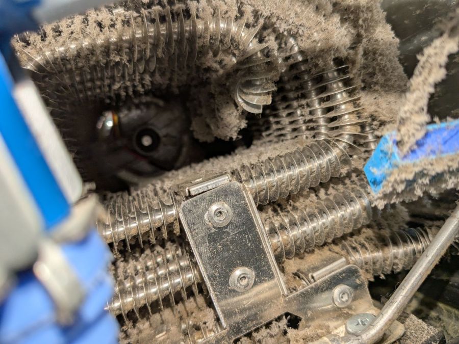
Looking into the intake end of those coils (on the right):
Samsung refrigerator coils – first intake view
So, yeah, I’m about to give them their first cleaning ever.
Five minutes of brushing fuzz, mostly into the vacuum, cleared a good bit of the exterior, but the interior needs more attention:
Samsung refrigerator coils – partial clean
Ten minutes later:
Samsung refrigerator coils – victory
Another five minutes:
Samsung refrigerator coils – intake cleaned
Making the coils cleanable and putting them where they could be cleaned were obviously not bullet-item goals for Samsung’s designers.
Although the coils are not perfectly clean, I don’t know how to get them any cleaner, despite knowing even a thin layer of fuzz kills the refrigerator’s much-touted energy efficiency. Perhaps blowing them off with compressed air, then cleaning a thin layer of dust off the entire kitchen, would help.
I think the refrigerator will be happier, at least for a while.
The light is unavoidably upside-down from the industrial standard, because I can’t don’t want to mount it on the laser cabinet, and my use of color does not match the industrial convention. Neither of which matter for my simple needs.
The blue and orange lights turn on when their inputs are active, so they positively show sensor satisfaction, rather than laser-disabling dissatisfaction. The entire stack lights up while the controller runs a job with assist air turned on, which is usually the case.
(See below for a slipstream update.)
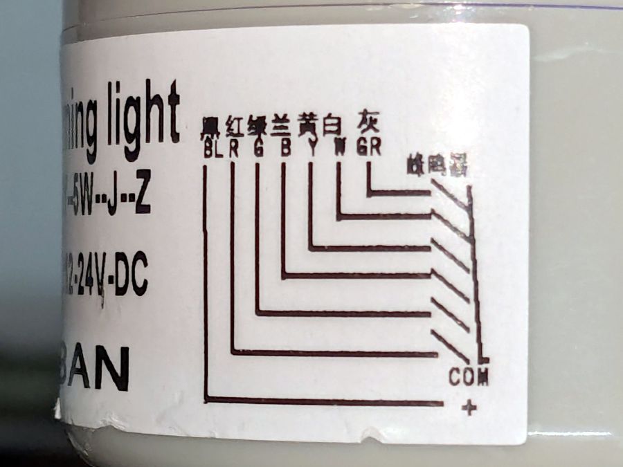
The wiring diagram on the case is the only documentation enclosed with the stack light:
Stack Light – label diagram
Any power supply between 12 VDC and 24 VDC will work and, contrary to the label, the COM lead can be either polarity: the light works in either common-anode or common-cathode configuration. Because the laser controller inputs and outputs are all low-active, I wired the COM terminal to +24 V, so pulling the other leads to GND turns on their lights.
The overall connection diagram, in order from easy to hard:
Stack Light – wiring diagram
Some of the details behind the diagram explain what’s going on.
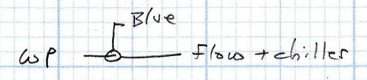
Stack Light – water protect wiring diagram
The water flow sensor is wired in series with the chiller, with a GND connection on the far end pulling the WP controller terminal low when both sensors are happy; the switches can handle another 50 mA of LED current with no problem.
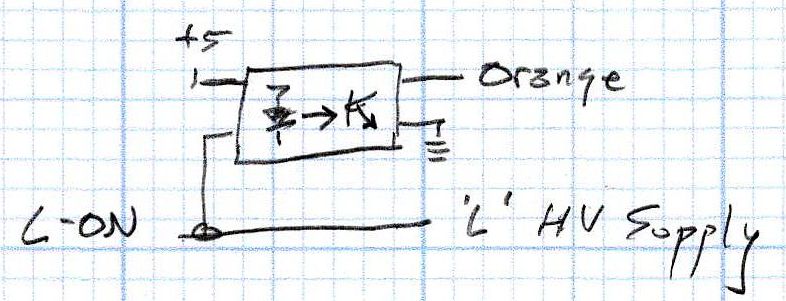
Stack Light – L-ON wiring diagram
The HV power supply has an internal pullup to +5 V on its L terminal, which means the L-ON output terminal sits at +5 V when the laser tube is off. Connecting the stack light directly to the L-ON terminal dumps the LED current into the 5 V supply through the pullup resistor, producing a somewhat weak glow in the LED when it should be off.
Running the optoisolator input from 5 V solves that problem, as its diode will be off when the L-ON output is high. When it’s low, the diode turns on, the isolator’s output transistors conduct, and the stack light gets the full 24 V it expects.
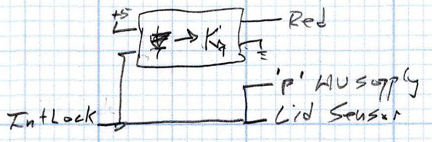
Stack Light – lid sensor wiring diagram
The lid sensor normally goes only to the IntLock controller terminal, but I also ran it to the otherwise unused P terminal on the HV power supply, in the possibly misguided belief it would prevent the supply from firing with the lid up if it failed like the first one. Those two inputs have 5 V pullups, so the optoisolator handles the stack light’s 24 V supply.
Stack Light – status and assist air wiring diagram
When I added the dual-path air assist plumbing, diode D1 turned on the air pump when either the Statusor the AuxAir output turned on. When the job calls for assist air, the AuxAir output opens a valve to increase the air flow.
The Status output is active when the controller is running a job and that’s generally the only time the AuxAir output will be active, but the machine console has an Air button that manually activates it, so diode D2 isolates the Status output in that unusual situation.
Slipstream update: I realized swapping the green & orange lights would make more sense:
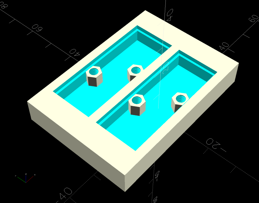
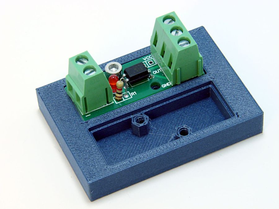
The little hex standoffs have M3 threads, although 6 mm screws are about as much as they’ll take. The recesses have clearance for the boost transistor underneath the PCB, but it’s your responsibility to not let random wires get in trouble with the exposed circuitry:
Optoisolator case
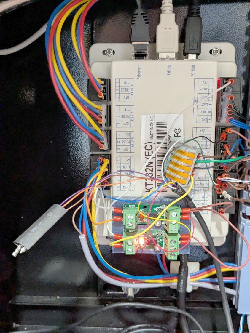
A strip of good foam tape sticks it to the controller:
Stack Light – controller wiring
Admittedly, the stack light wiring remains something of a hairball, but it’s in a good cause.
The OpenSCAD code can build as many cavities as you need:
This file contains hidden or bidirectional Unicode text that may be interpreted or compiled differently than what appears below. To review, open the file in an editor that reveals hidden Unicode characters.
Learn more about bidirectional Unicode characters
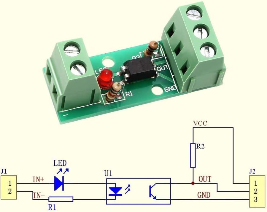
I’ll go into the motivation for optocouplers along with the laser controller wiring details.
As delivered, the PCB has:
R1 = 1 kΩ (a convenient 1 V/mA current sense)
R2 = 10 kΩ (a rather high-value pullup)
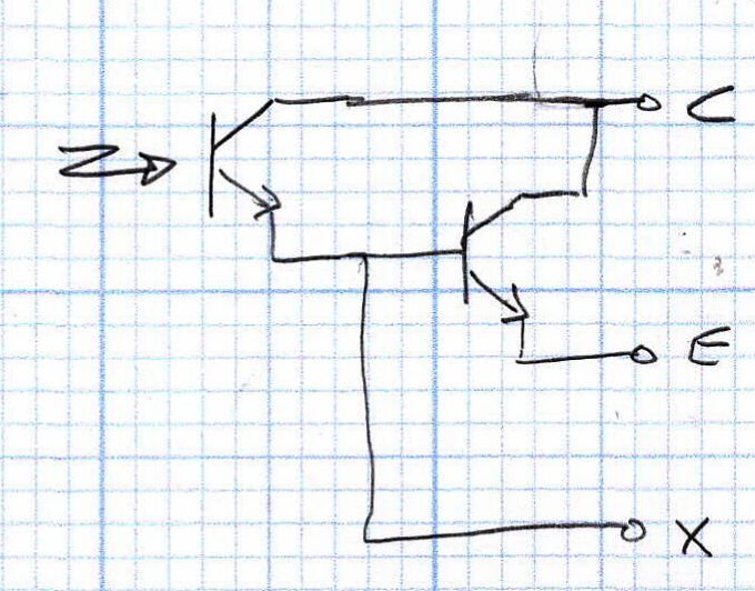
The idea is to add an able-bodied transistor to the output in a Darlington configuration:
Optoisolator – Darlington output
Some rummaging produced a small bag of 2N3904 transistors, although nearly any small NPN transistor will suffice. Removing R2 cleared the field for modification:
Optoisolator modification – top
The 2N3904 transistor (with the usual EBC pinout) fits face-down under the PCB:
Stack Light – optoisolator transistor
The cross-legged layout conceals the emitter and base leads being soldered snugly to the former OUT and GND terminals, respectively, with the collector going to the VCC terminal. The terminals thus become:
VCC → Collector
OUT → Emitter
GND→ X (no connection)
Although I have little reason to believe the EL817 chips are anything other than what they claim to be, their topmarks seemed rather casual:
EL817 optocoupler – top view
The other four chips carried C333 rank + date codes.
The datasheet says the C means the Current Transfer Ratio is 200% to 400%: the output current should be 2× to 4× the diode current. The test condition are 5 mA into the diode and 5 V across the transistor terminals. A quick test:
2 mA → 4 mA = 2×
5 mA → 15 mA = 3×
10 mA → 35 mA = 3.5×
12 mA → 40 mA = 3.3×
The output transistor is rated only to 50 mA, so I stopped at 40 mA. The CTR is between 200% and 350% over that range, suggesting the parts are really real.
The 2N3904 should have an hFE above 60 in that current range and multiply the EL817 gain by about that amount. Another quick test in the Darlington configuration, now with the 5 V supply across the 2N3904:
100 µA → 8.1 mA = 81×
250 µA → 43 mA = 172×
500 µA → 83 mA = 166×
The overall current gain is 40× to 50×, less than the estimate, but plenty high enough for my purposes. If you cared deeply, you’d run a circuit simulation to see what’s going on.
Knowing I needed only 50-ish mA, stopping with the transistor burning half a watt (because VCE is held at 5 V) seemed reasonable. In actual use, VCE will be on the order of 1 V and the dissipation will be under 100 mW.
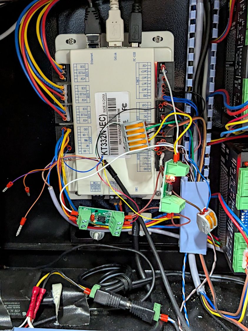
A quick test shows they work as intended:
Stack Light – controller hairball wiring
But, yeah, talk about hairballs. Those things cry for little housings to keep them out of trouble.
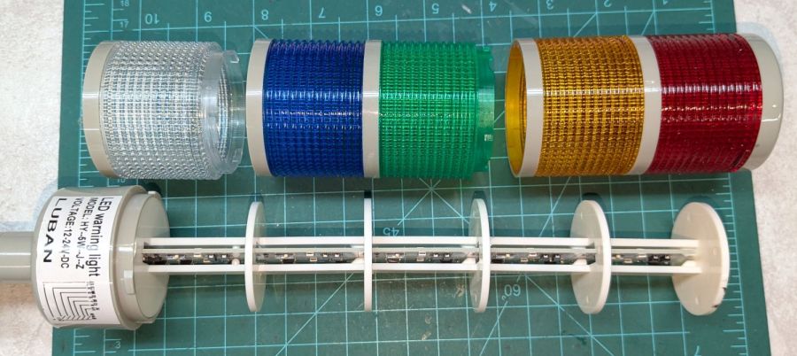
Having external indications for the laser cutter’s internal status signals seemed like a good idea and, rather than build the whole thing, I got a five-layer stack light:
Stack Light – disassembly
It arrives sans instructions, apart from the data plate / wiring diagram label on the housing, so the first puzzle involves taking it apart to see what’s inside. My motivation came from a tiny chip of blue plastic on the kitchen table where I’d opened the unpadded bag. Apparently, a mighty force had whacked the equally unpadded box with enough force to crack the blue lens, but I have no idea how the sliver escaped the still-assembled stack.
Anyhow, hold the blue/green lenses in one hand and twist the red/yellow lenses counterclockwise as seen looking at the cap over the red layer. Apply more force than you think appropriate and the latches will reluctantly give way. Do the same to adjacent layers all the way down, then glue the blue chip in place while contemplating other matters.
A switch on each layer selects either steady (the default and what I wanted) or blinking (too exciting for my needs). Reassemble in reverse order.
A Stack Light generally mounts on a production-line machine which might have a suitable cutout for exactly that purpose. I have no such machine and entirely too much clutter for a lamp, so I screwed it to a floor joist over the laser:
Stack Light – installed
The tidy blue PETG-CF base started as a scan of the lamp’s base to serve as a dimension reference:
Stack Light – base scan
Import into LightBurn:
Draw a 70 mm square centered on the workspace
Round the corners until they match the 13 mm radius
Draw one 5.6 mm circle at the origin
Move the circle 52/2 mm left-and-down
Turn it into a 4 element array on 52 mm centers
Verify everything matches the image
Export as SVG
Import into Inkscape:
Put the perimeter on one layer
Put the four holes on another
Center around an alignment mark at a known coordinate
Save as an Inkscape SVG
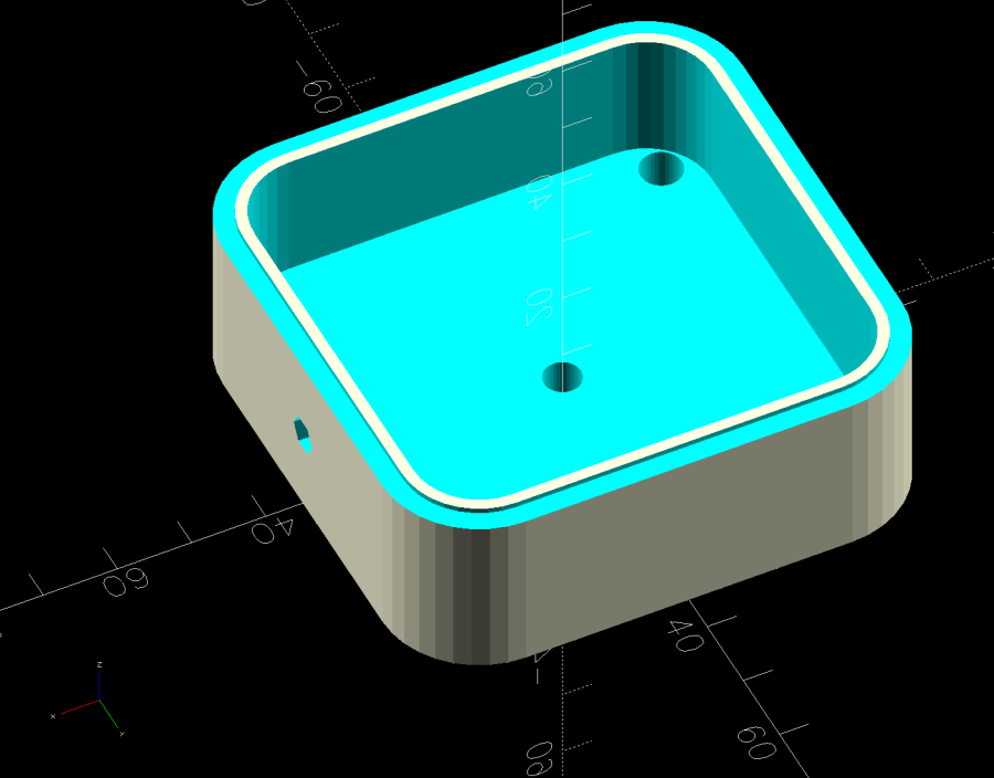
Import into OpenSCAD, extrude into a solid model, and punch the holes:
Stack Light Mount base – solid model
The lip around the inner edge aligns the lamp base.
If I ever make another one, I’ll add pillars in the corners to put the threaded brass inserts close to the top for 10 mm screws instead of the awkward 30 mm screws in this one. More than a single screw hole in the bottom would align it on whatever you’re indicating.
This file contains hidden or bidirectional Unicode text that may be interpreted or compiled differently than what appears below. To review, open the file in an editor that reveals hidden Unicode characters.
Learn more about bidirectional Unicode characters
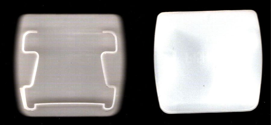
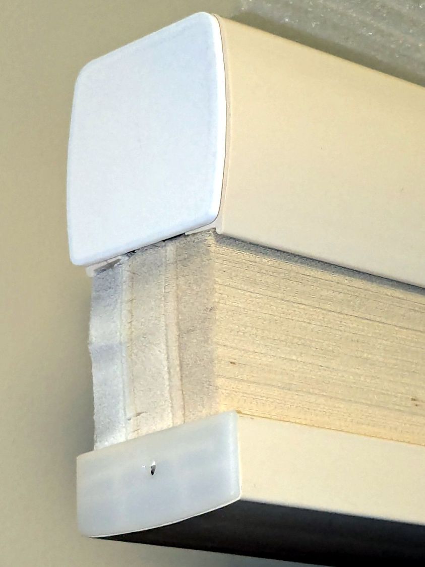
While tracking down an air leak in a living room window, I noticed one of the cellular blinds was missing an end cap, so I scanned a pair of surviving caps:
It is slightly tilted, but that doesn’t matter. You could devote more time to smoothing / reverse-engineering the shapes, but that doesn’t make much difference, either.
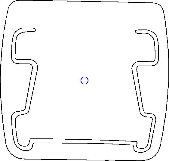
Inkscape exports the SVG coordinates with respect to the overall page origin in the lower left corner, so when OpenSCAD imports the SVG the paths end up far away from the origin. The trick is to put a 2 mm diameter circle at a known location, center the paths around it, then have OpenSCAD use the circle’s location to recenter the paths.
Because Inkscape uses the lower left corner of each shape as its origin, you must put the circle at (99,99) to have its center at (100,100). That is one of the many reasons you (well, I) can’t use Inkscape as a CAD program.
Import into OpenSCAD, recenter, and extrude the shapes:
CapCenter = [100,100];

PlateThick = 1.8;       // thickness of visible end cap

HolderTall = 10.0 + PlateThick;

union() {
  linear_extrude(height=PlateThick)
      translate(-CapCenter)
            import("Living Room shade end caps - Inkscape.svg",layer="Exterior");
  linear_extrude(height=HolderTall)
      translate(-CapCenter)
            import("Living Room shade end caps - Inkscape.svg",layer="Retainer");
}
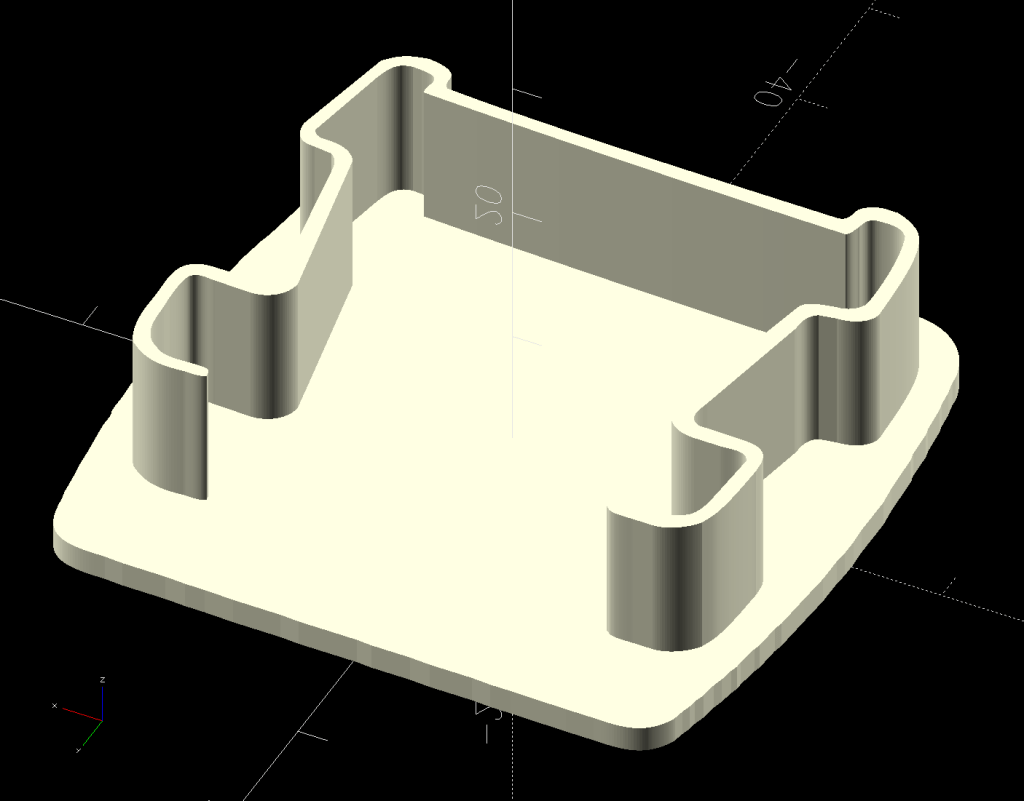
Which produces a solid model:
Living Room shade end caps – solid model
Save the model as 3mf, import into PrusaSlicer, and slice:
Living Room shade end caps – PrusaSlicer preview
Making the retainer shape a little wider would be a good idea to get better infill, but it’s a slip fit into the blind (surely why it fell out long ago) and need not withstand any stress.
Print as usual:
Living Room shade end cap – on platform
And then It Just Works™:
Living Room shade end cap – installed
It’s sitting atop a bookcase while I finish tinkering with its window.
All that seems like a lot of fiddling around, but it uses each program to its best advantage and it’s surprisingly easy after the first few models.


