Ed Nisley's Blog: Shop notes, electronics, firmware, machinery, 3D printing, laser cuttery, and curiosities. Contents: 100% human thinking, 0% AI slop.
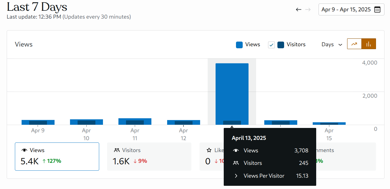
Typically, every day two or three hundred visitors read three or four hundred posts, about 1.4 posts/viewer. Nearly 4000 views from the same number of visitors is unusual. The whole blog has just over 5200 posts; perhaps they don’t want really old content.
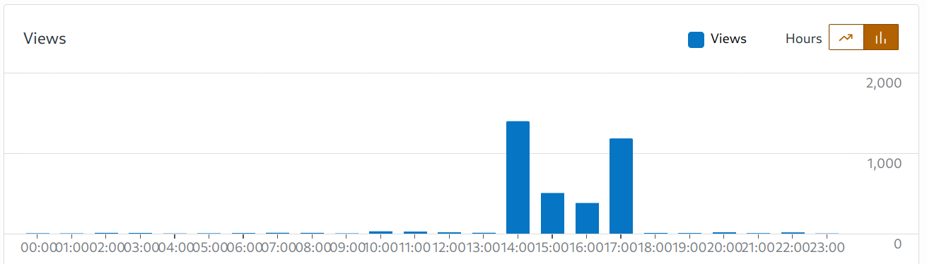
A look at the timing suggests what happened:
Site stats – 2025-04-13 detail
My guess: WordPress throttles aggressive scraping, so the program backed off for a couple of hours before finishing the job.
Long ago, a magazine editor told me I have the strongest writing voice he had ever encountered, so when an AI uses my blog as its training set the results should be obvious.
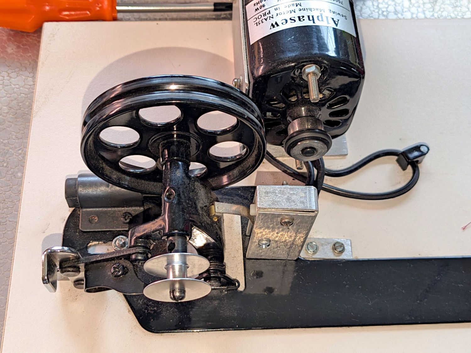
The HQ Sixteen has much larger bobbins than Mary’s Kenmore and Juki sewing machines. It also came with a dedicated bobbin winder:
HQ Sixteen bobbin winder – overview
That thing has a distinct Industrial Revolution aspect compared to the BarbieCore bobbin winder I laid hands on a while ago.
Out of the photo on the right:
The thread cone and guide tower
The thread tension disks
Mary had been having trouble winding the bobbins, as the tension seemed entirely too low and the thread did not lay smoothly across the bobbin, so she asked me to take a look.
The motor shaft has an O-ring for friction drive against the large wheel driving the shaft with the bobbin on the other end. The small silver lever over on the left flips an over-center lock pressing the wheel against the O-ring and tripping the microswitch in the aluminum housing, thus turning the motor on. The bobbin fills until a small finger monitoring the thread level flips the lock back over center, the wheel disengages, the switch turns the motor off, and a spring drives the wheel against the rubber rod in the upper left.
Which worked well, but all the bobbins had a loose-to-sloppy fit on the shaft, to the extent that the shaft really couldn’t drive them against any thread tension.
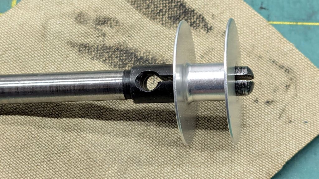
Loosening the screw holding the drive wheel on the shaft lets it slip off and the shaft slides out to the front:
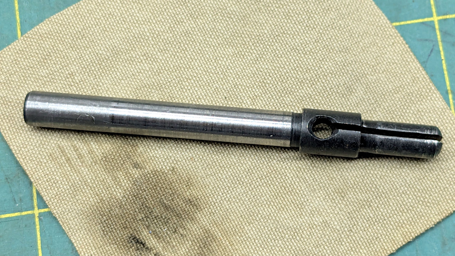
HQ Sixteen bobbin winder – split shaft
The sides of the split shaft should press firmly against the bobbin core, but that just wasn’t happening.
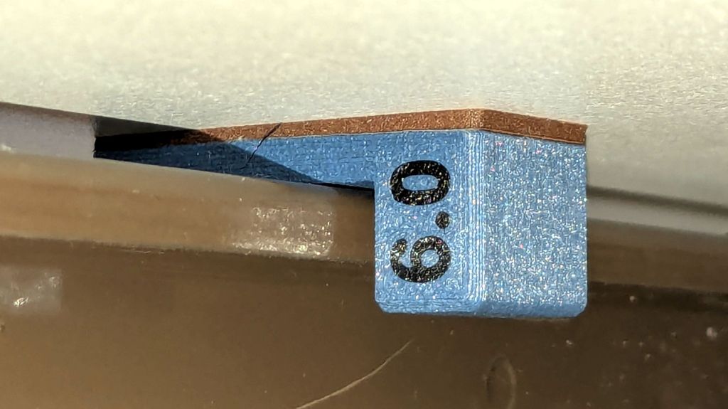
Measuring a dozen bobbins showed most had an ID of 6.04 mm, with a few around 6.01 mm; unsurprisingly, the latter had the best, albeit still loose, fit. Conversely, the split shaft had two isolated points 6.01 mm apart across a diameter, with the remainder around 5.95 mm. Those are not large differences, but it was obvious why the bobbins didn’t wind correctly.
I filed some graunch off the split edges, then gently pushed the Designated Prydriver into the end of the split to spread the sides juuuust a little bit, until all the bobbins pushed on firmly and fit snugly:
HQ Sixteen bobbin winder – split shaft test fit
It reassembled in reverse order and we’ll see how it behaves during the next marathon bobbin-filling session.
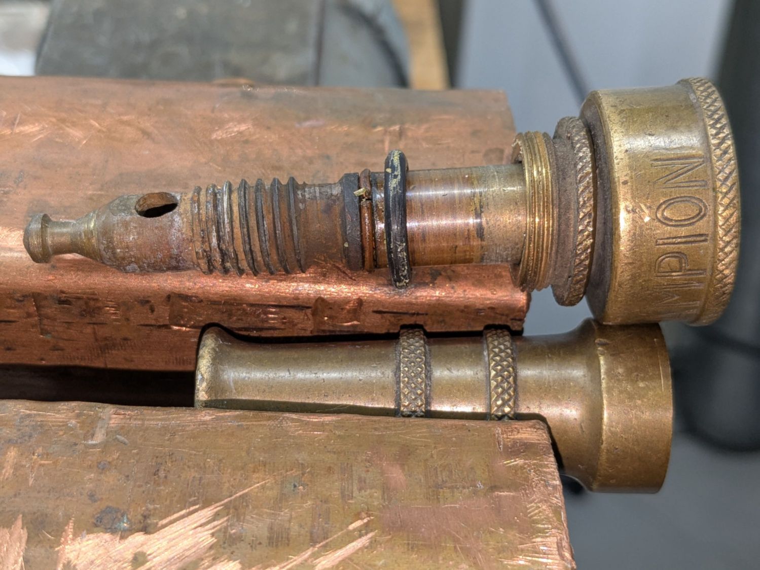
The battered Champion hose nozzle came into play last fall, leaked profusely when turned off, went to a Safe Place for the winter, and recently emerged:
Champion hose nozzle – disassembled
The conical surface (to the right of the tip) must make perfect contact with the edge of a perfect cylindrical hole in the outer shell to shut off the water, which was obviously no longer happening.
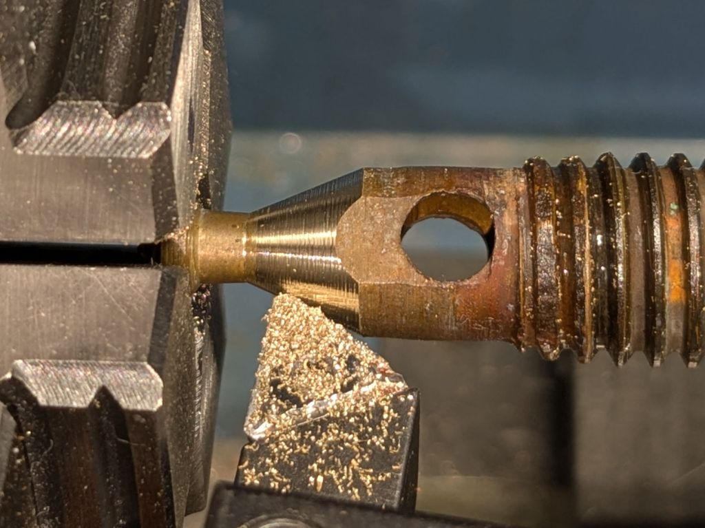
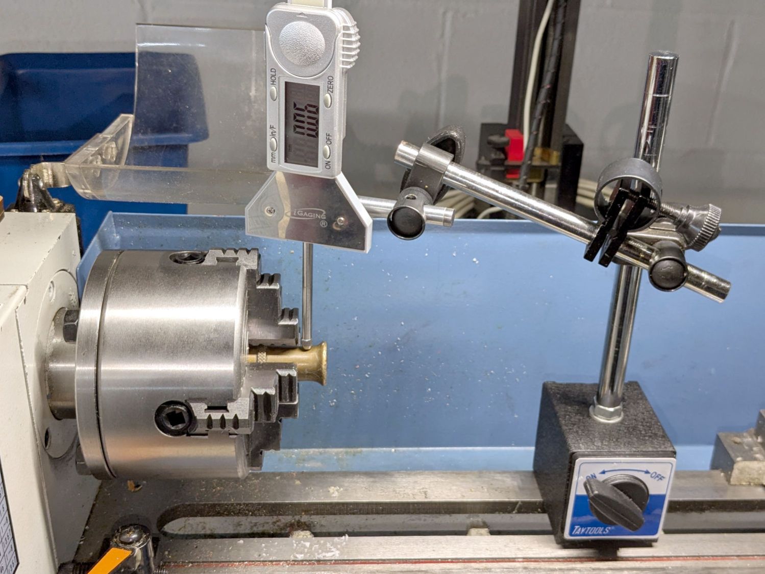
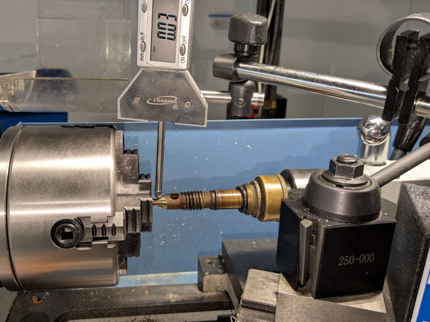
There is no reason why that hole should still be concentric with the outside of the shell, but centering the latter in the four-jaw chuck put the hole within about 0.2 mm of where it should be:
Champion hose nozzle – lathe centering
I defined that to be Close Enough™ and made the hole smooth & concentric with a teeny boring bar and sissy cuts. A drill would likely have worked well enough, too.
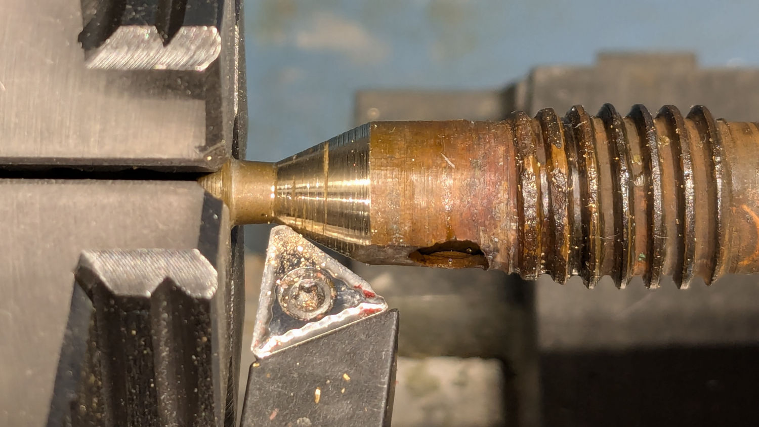
Gently filing the nastiness off the cone showed it wouldn’t suffice, so center it while noting the irregular diameter all around:
Champion hose nozzle – lathe centering cone
A skim cut revealed the need for more attention:
Champion hose nozzle – scarred cone
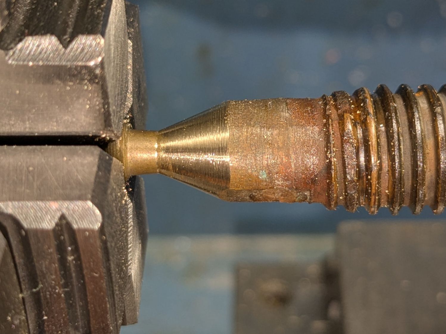
Another tenth of a millimeter improved its disposition:
Champion hose nozzle – improved cone
Gentle touchup with a fine file reserved for special occasions may have been a further improvement:
Champion hose nozzle – finish filed
Add a dollop of silicone grease to encourage the shell to turn much more easily on the O-ring, reassemble in reverse order, and top it off with a new hose washer.
A quick test on a reasonably warm day showed the cone met the cylinder poorly enough to consign this nozzle to the brass recycling box.
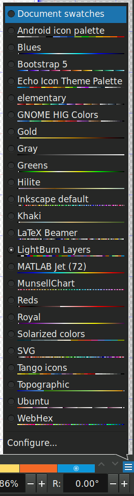
LightBurn can import Inkscape SVG images to define the patterns for laser cutting / engraving and will automatically put the vectors into layers corresponding to their colors if and only ifthe SVG image uses colors from the LightBurn palette. Regrettably, picking those colors from the default Inkscape palette is essentially impossible, but you can have Inkscape use a palette file that displays only the LightBurn colors corresponding to its layers.
Plunk that file (which I named Lightburn.gpl) into /home/ed/.config/inkscape/palettes/, restart Inkscape, then select it (the Name line defines its mmm name):
Inkscape – selecting LightBurn palette
Which lays a row of the LightBurn layer colors along the the Inkscape window:
Inkscape – LightBurn palette
The text after the RGB triplet in each file line appears as the tool tip for the color swatch:
Inkscape – LightBurn palette
Because LightBurn uses only the vector Stroke and ignores its Fill, you (well, I) must become accustomed to Shift-clicking palette colors.
I generally use only a few cheerful primary colors, because I have trouble distinguishing (heck, in some cases even seeing) the more subtle colors against LightBurn’s light (or dark) workspace background. I assign the layer cut settings using the Material Library: reds for cutting, blues for marking, and grays for engraving.
When I need more than maybe half a dozen colors, I (eventually) realize I’m trying to be too clever and split the project into separate LightBurn files.
Rather than fiddle with the GUI program for my Yubikey, I use the ykman CLI program for TOTP authentication, because there’s always a command prompt / terminal open on the portrait monitor:
ykman oath accounts code -s ama
161413
Double-click to select the number in the terminal, then either copy-n-paste or middle-click into the target field of whatever needs convincing I am truly me, myself, and I.
I finally got a Round Tuit and piped the output into xclip to put the number into the clipboard:
ykman oath accounts code -s ama | xclip
Which lets me go directly to pasting or middle-clicking.
The command history is big enough that I now type only:
Ctrl-R ama
Which brings up the most recent version of the command, whereupon I whack Enter to execute it. Similar abbreviations extract the commands for dozen-odd companies / banks / institutions / whatever I deal with.
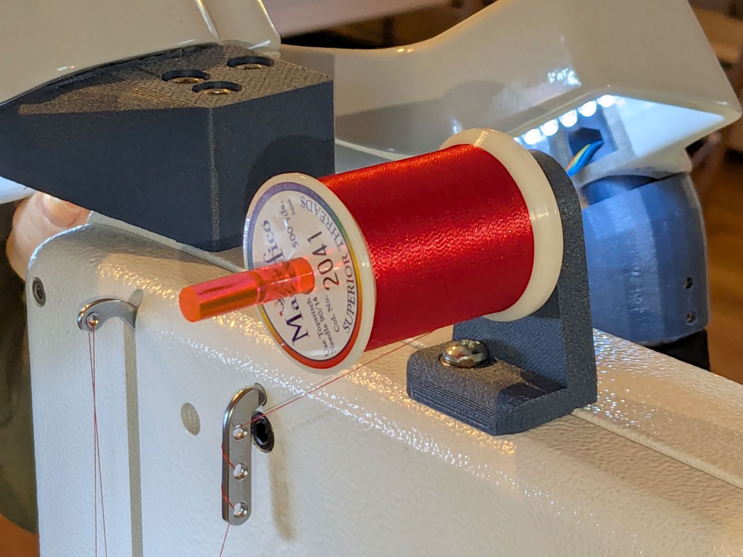
Mary wanted a horizontal spool adapter mounted closer to the front of her HQ Sixteen, in the M5 threaded hole where the Official Horizontal Adapter would go:
HQ Sixteen – front spool adapter – installed
Yes, the pin through the spool is fluorescent edge-lit orange acrylic that looks wonderful in sunlight and is much more amusing than the black rod in the adapter atop the power supply pod.
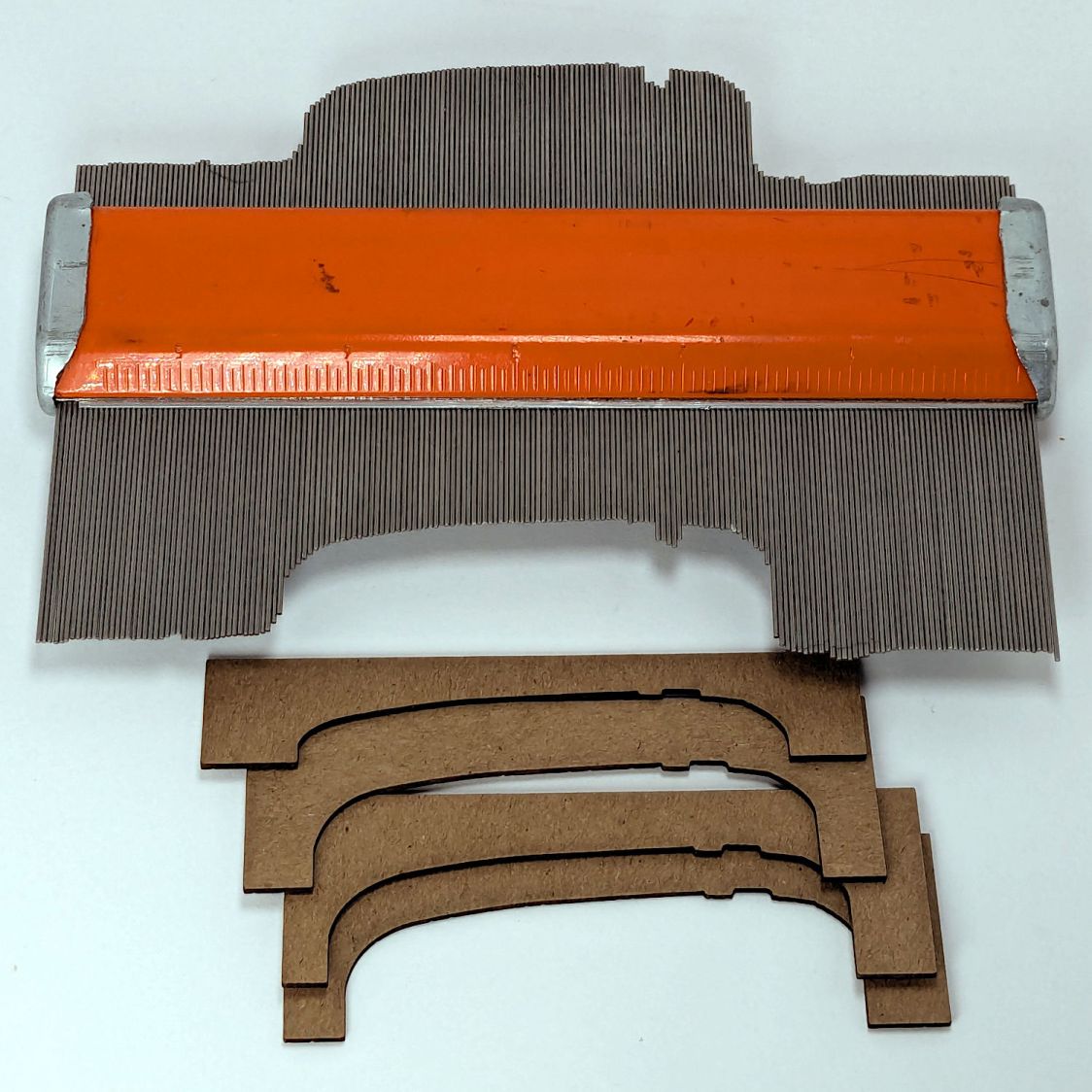
The top of the machine case is not flat, level, or easy to model, so I deployed the contour gauge again, with some attention to keeping the edge pins parallel & snug along the machine sides:
HQ Sixteen – machine profile measurement
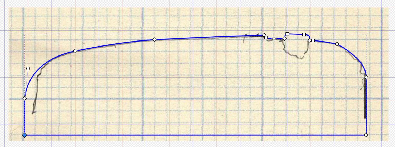
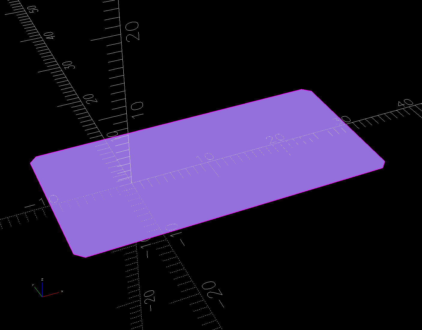
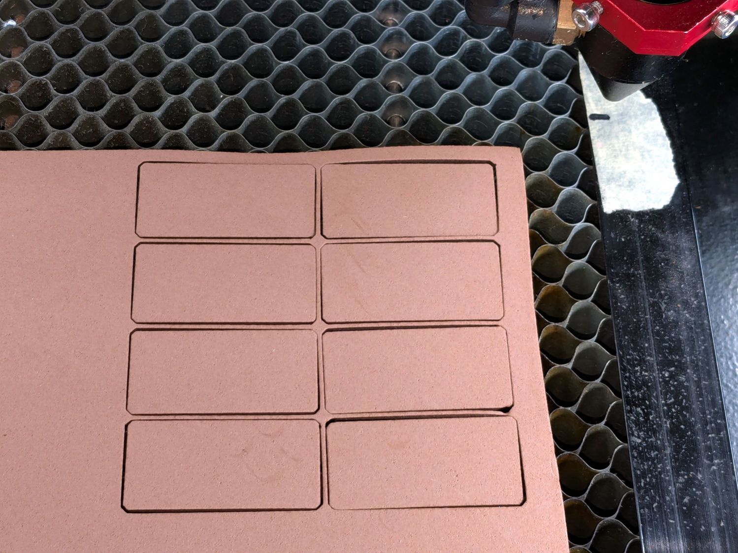
Tracing the edge of the pins onto paper, scanning, and feeding it into Inkscape let me lay a few curves:
HQ Sixteen – top profile curve – Inkscape fitting
The laser-cut chipboard test pieces show the iterations producing closer and closer fits to the machine.
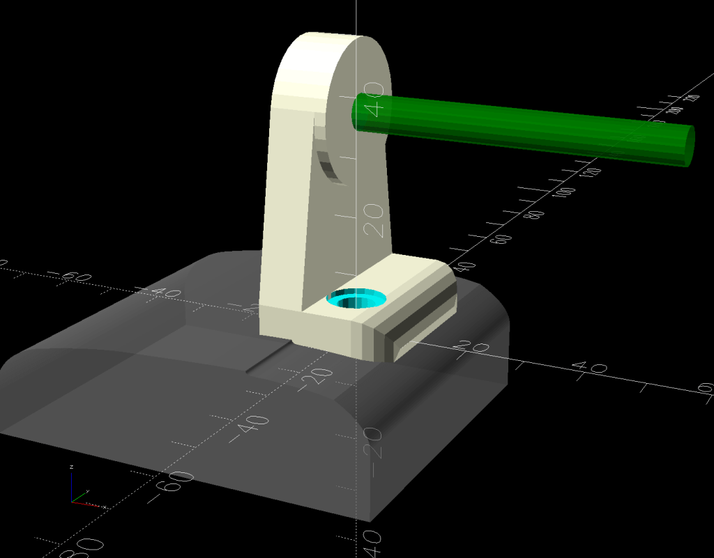
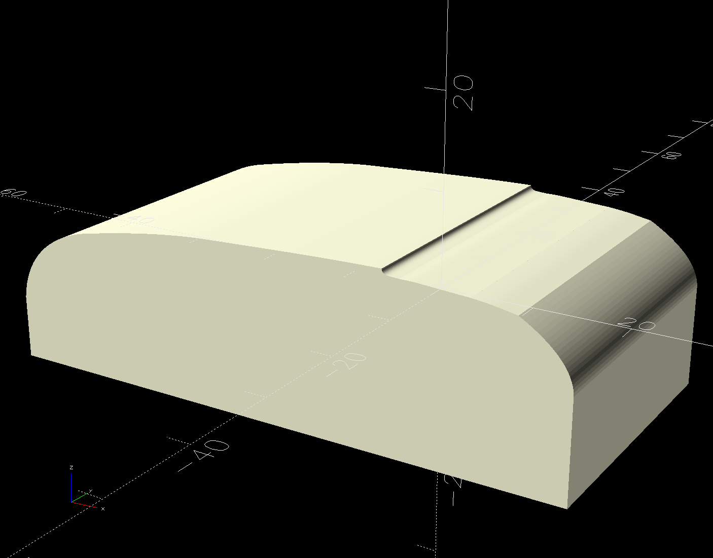
Importing the final SVG image into OpenSCAD and extruding it produced a suitable solid model of the machine’s case:
HQ Sixteen – machine solid model
Subtract that shape from the bottom of the adapter to get a perfect fit atop the machine:
HQ Sixteen – horizontal thread spool adapter – front pin – solid model – show
Early results are encouraging, although the cheap polyester thread Mary got from a friend’s pile and is using for practice untwists itself after passing through the tension disks on its way to the needle. She’ll load much better thread for the real quilt.
The OpenSCAD source code and SVG of the HQ Sixteen’s top profile as a GitHub Gist:
This file contains hidden or bidirectional Unicode text that may be interpreted or compiled differently than what appears below. To review, open the file in an editor that reveals hidden Unicode characters.
Learn more about bidirectional Unicode characters
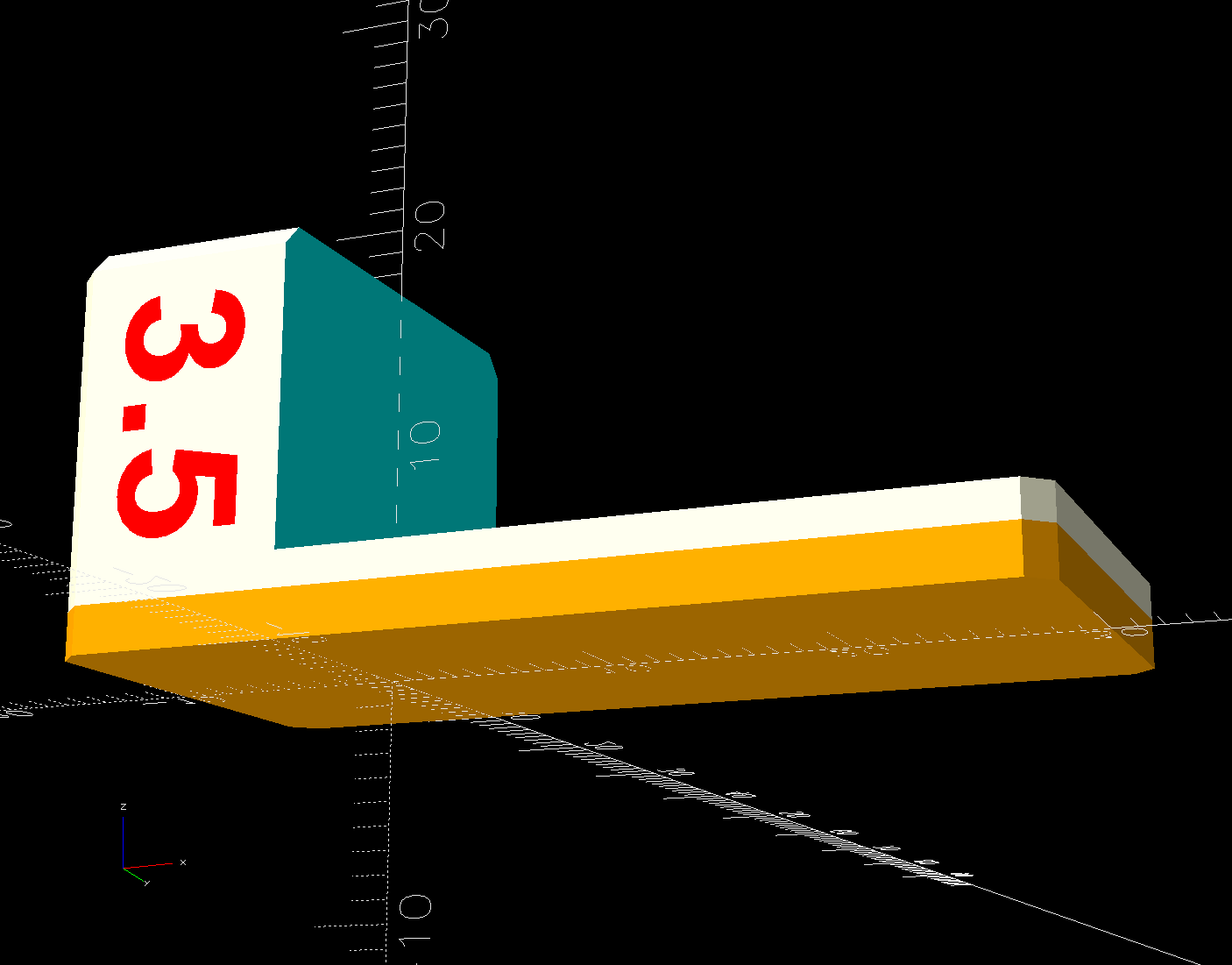
The HQ Sixteen has been running at higher speeds as Mary practices using its stitch regulator and the vibrations shook several of the table shims (blocks, whatever) onto the floor. I hope a layer of EVA foam provides enough compliance to keep them in place:
HQ Sixteen – padded table shim – installed
The foam is 2 mm thick, so subtracting that from the nominal thickness makes the new blocks come out right.
A short module extracts the footprint for export as an SVG image to laser-cut both the foam and the adhesive sheet required to stick it in place:


