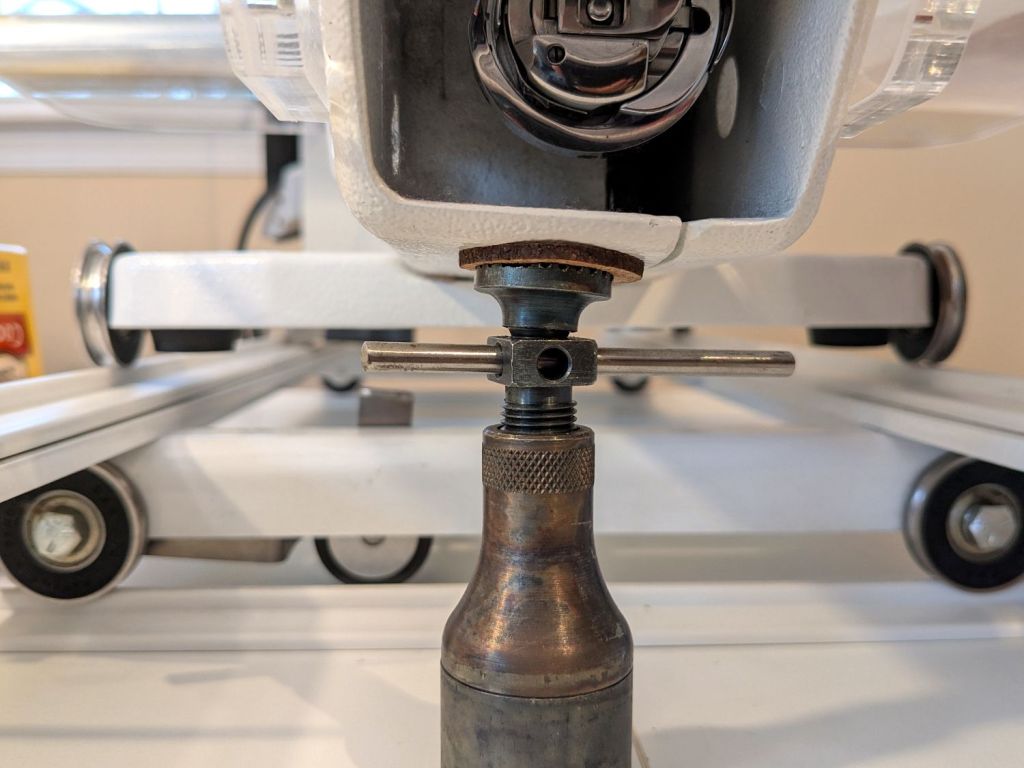
The HQ Sixteen came with a small red-dot laser pointer attached to a threaded pin:

The pin can go into either of a pair of threaded holes in the machine castings or the laser + clamp can, as in the picture, attach to a spool pin.
With a “pantograph” pattern laid along the rear of the table, you can stitch that design (at full size, hence “pantograph” seems aspirational) by guiding the red dot along the lines. The laser’s flimsy clamp mount seems prone to move at the worst possible moment, so neither of us liked the idea.
Mary is good at free-motion quilting and says she’s unlikely to use the laser, but I figured staying slightly ahead of the curve would be a Good Idea. Bonus: 3D printing.
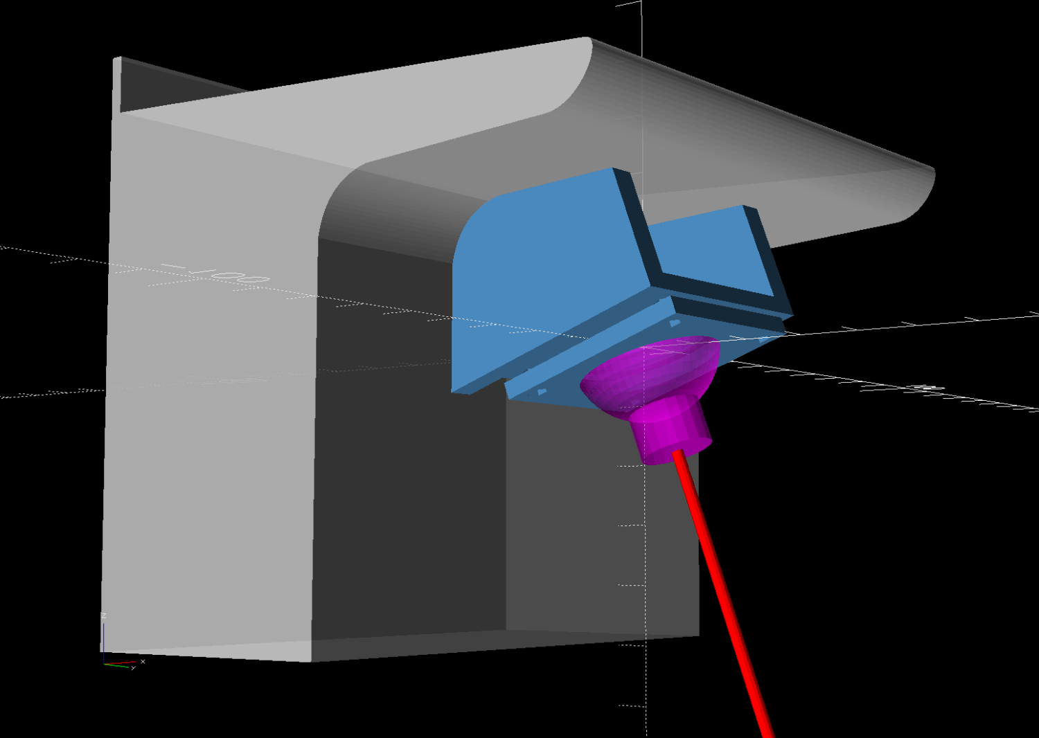
The general idea is to tuck a (similar) red-dot laser module under the overhang of the electronics pod, with a ball mount for easy aiming and stable setting, something like this:
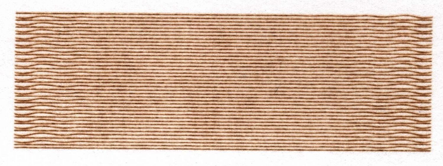
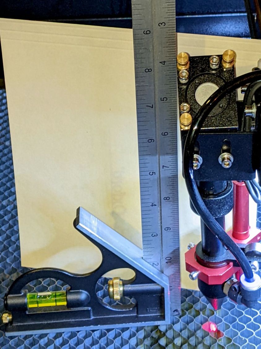
Fitting the mount into that curved corner requires a model of the electronics pod, so I held a pad of paper against the pod and traced the outline:

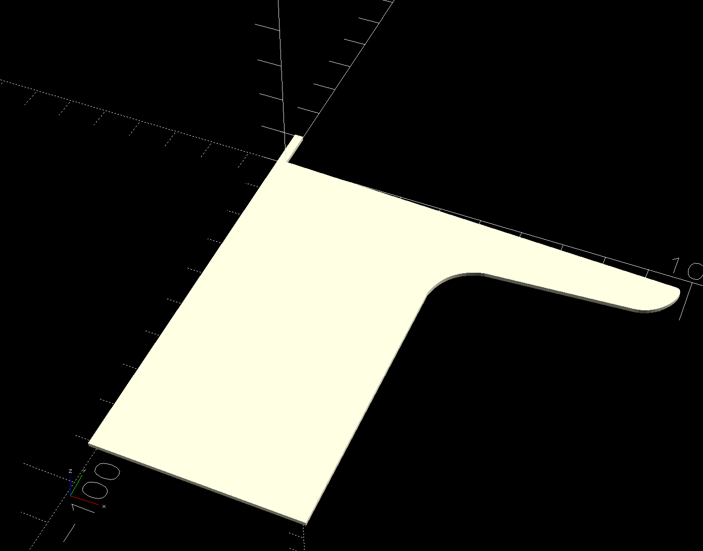
Scan it, import the image into Inkscape, fit lines and curves around the shape:

I only needed the top of the pod, so the bottom is truncated from the actual 250 mm height.
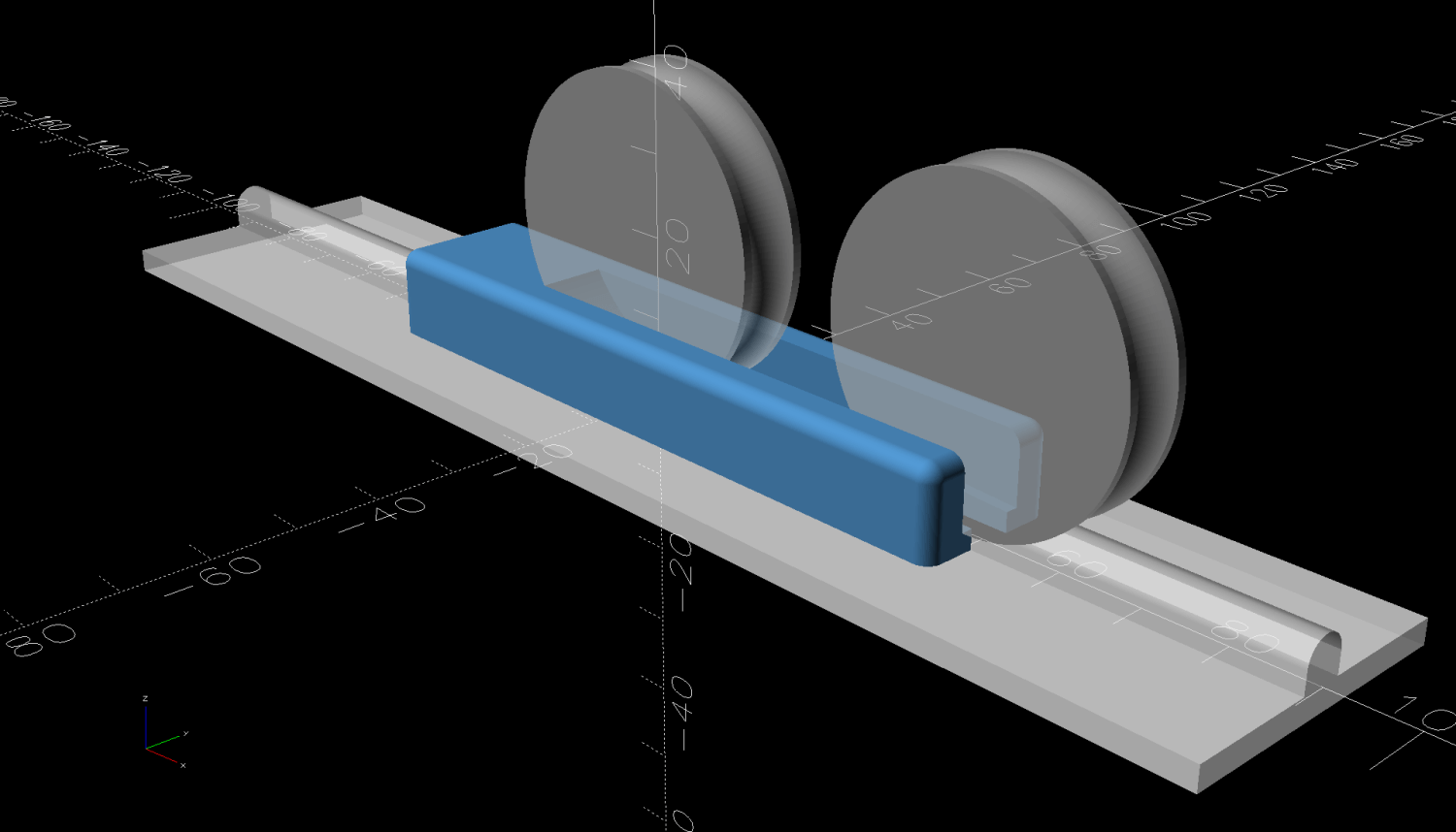
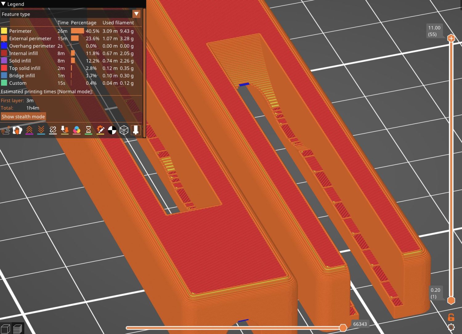
Save the SVG, import into OpenSCAD, extrude to match the pod’s 110 mm width:
module Pod() {

    xrot(90)
    down(PodWidth/2)
        linear_extrude(height=PodWidth,convexity=5)
            translate(PodRecenter)
                import("HQ Sixteeen - pod profile.svg",
                        layer="Pod Profile");
}
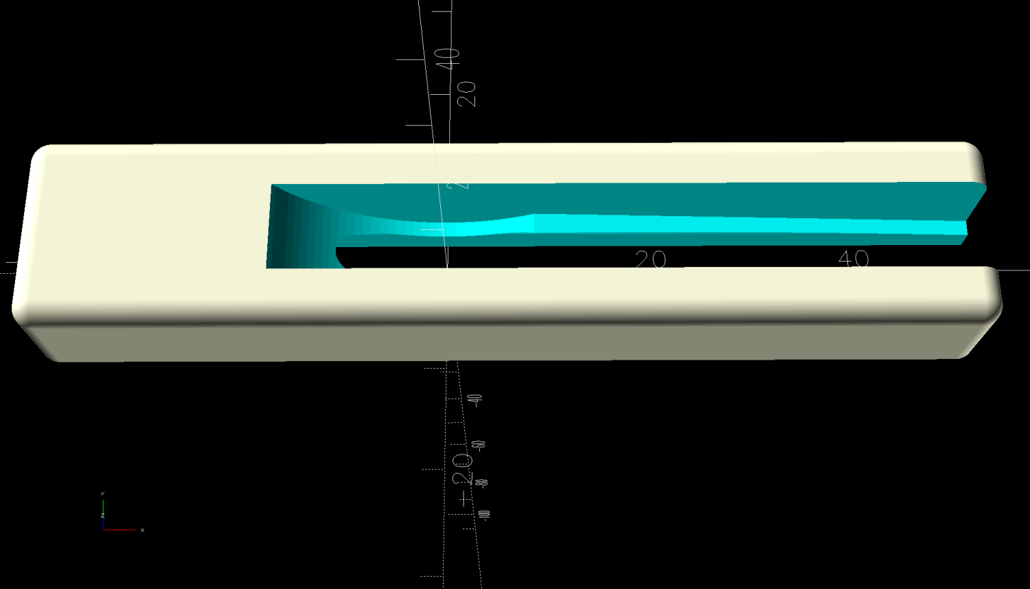
The model origin is where the upper lip meets the slightly sloped top surface in the middle of the extrusion, because that’s the only easy-to-locate feature:

Something Has Changed in the Inkscape SVG → OpenSCAD model chain, because the parts of an Inkscape drawing lying outside the page boundary are no longer cropped from the OpenSCAD model. Now, simply putting a feature at the Inkscape origin at the lower-left corner of the document’s Page produces a complete OpenSCAD 2D shape with that feature at the 3D coordinate origin.
For reference:
- Inkscape v1.4
- OpenSCAD 2025-02-11 via AppImage
The Inkscape layout with the entire shape off the page:

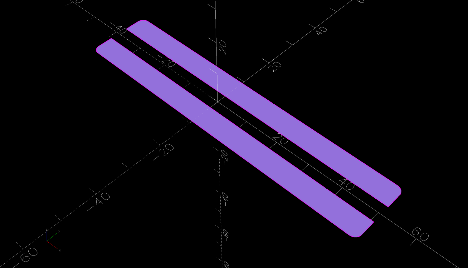
The 2D imported shape in OpenSCAD with a matching origin:
I do not know what changed or if, in fact, my misunderstanding of how things worked required the previous workaround, but this is much better. The OpenSCAD code includes a [0,0] offset value, should you need it.
More on the mount tomorrow …