Ed Nisley's Blog: Shop notes, electronics, firmware, machinery, 3D printing, laser cuttery, and curiosities. Contents: 100% human thinking, 0% AI slop.
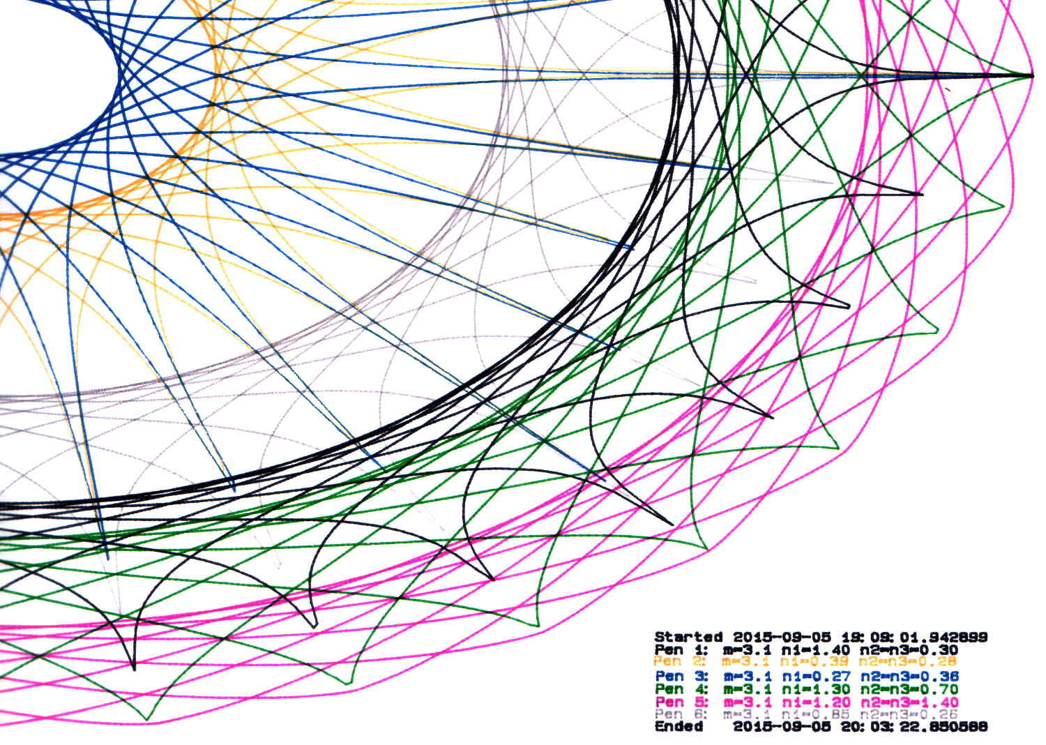
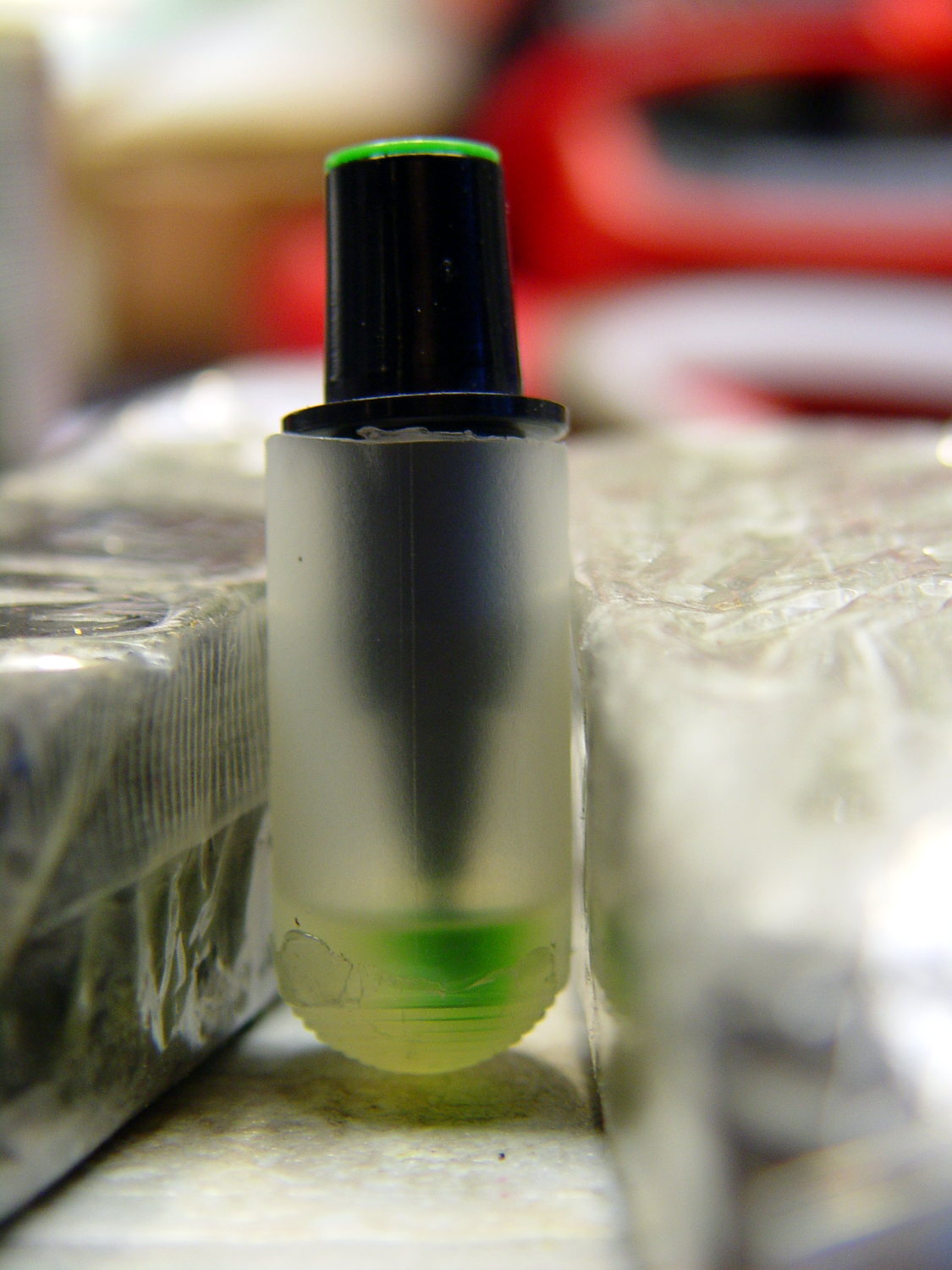
During this plot, an Inmac purple pen (in the Pen 5 slot) pretty much ran out of ink:
HP 7475A – Pen 5 before refill
It printed the legend perfectly and started the trace solidly enough, proceeding upward from the far right, but after ten circuits around the center it returned dragging a very faint line behind it.
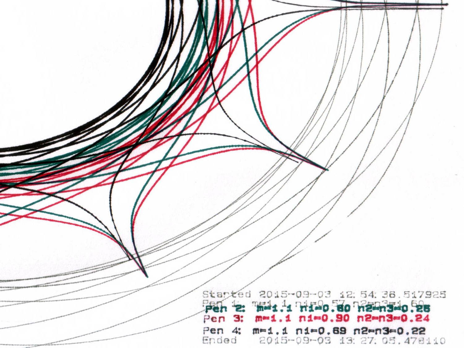
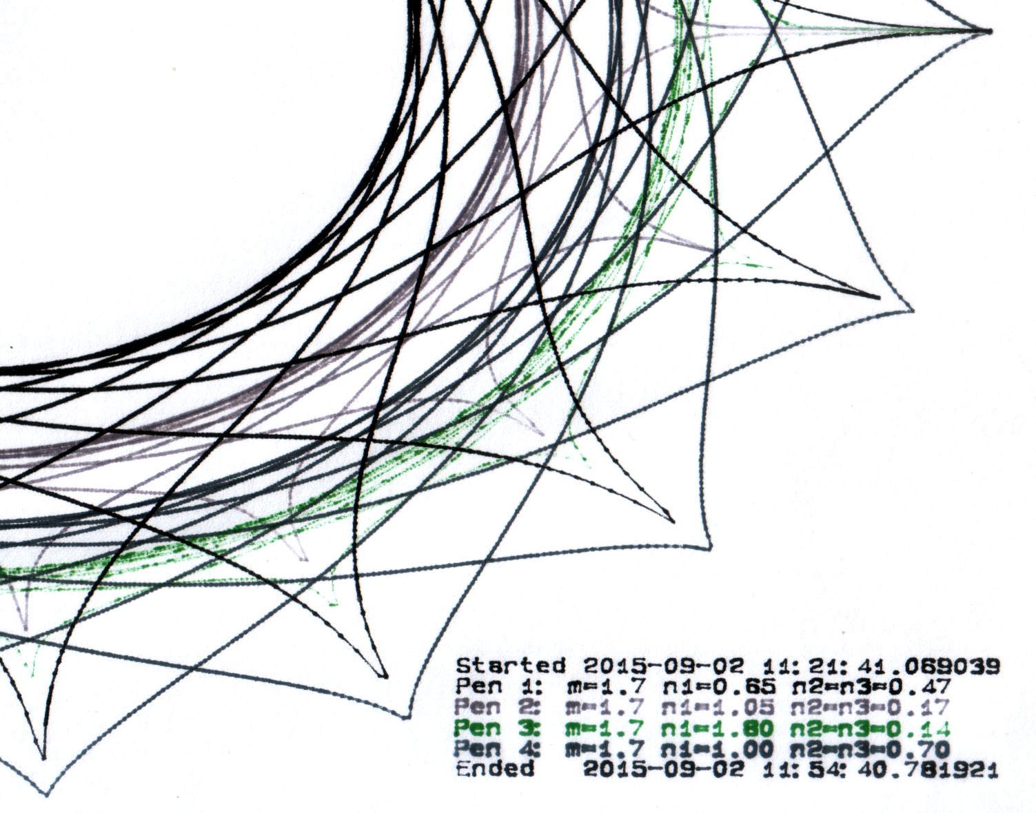
Just for a change, I punched a new-old-stock Inmac pen from its sealed blister pack, only to find that it left a spotty trail. These being easy to refill, I popped the top, flipped the fiber reservoir, added ten drops of HP2000C black (i.e., not the crappiest ink I’ve ever used), and scribbled a few feet to get it started again. It left a good-enough trace, so I ran an A-size plot with the ball pen, two liquid ink pens, and a refilled ceramic pen:
HP 7475A – Inmac ball – liquid – ceramic – pens
It’s a bit pallid compared with the black ceramic pen. The line is continuous and, in comparison with all the other plotter pens in the collection, very very very fine.
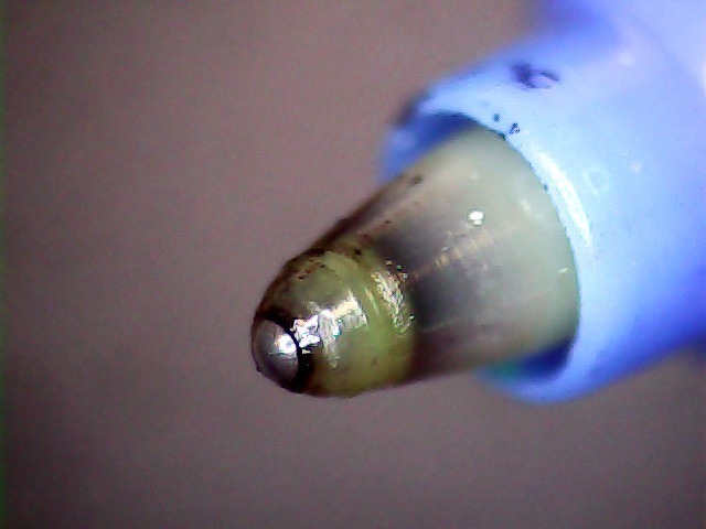
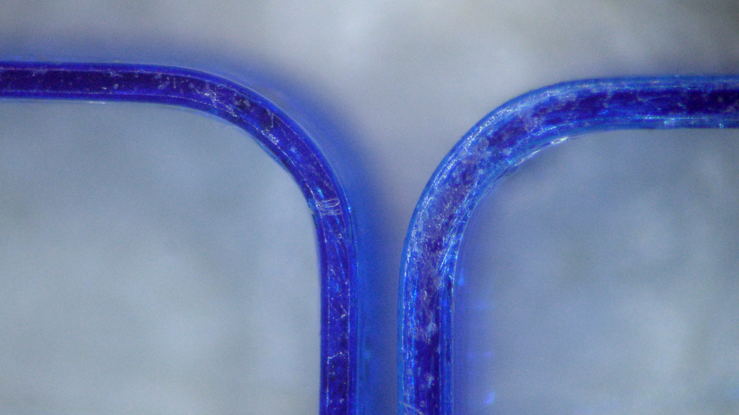
Turns out that it’s a miniature ball-point pen:
Inmac ball pen tip
I’m certain that water-based inkjet juice isn’t the right stuff for a ball-point pen, which may account for the lack of color. It’d be most appropriate for a document with fine text details, not that I must plot any of those at the moment.
There’s a bag with a dozen more of ’em in various cheerful colors, so, if I could just think of something that needed stubby ballpoint pens, I’d be all set.
It might be intended for a different HP plotter that applies more downforce to give the ball more encouragement. We’ll never know…
Being that type of guy, I measure the single-layer skirt threads to keep track of the platform alignment. Most of the time, nothing happens, because the M2 has a remarkably stable platform, but some of the objects I’d done in early August showed more than the usual variation and, worryingly, no discernible trend.
Adjusting the platform alignment between each of those sets produced no consistent effect, which is most unusual. The X in the bottom set shows where that thinwall box came unstuck from the platform, indicating that the clearance was considerably more than the nominal 0.25 mm layer height.
Peering under platform revealed something else that was quite unusual:
M3 washer – bad seating
That washer should be flat against the spider mounting plate. My first thought was a burr on the plate, but that didn’t make any sense, as the plate was clean & smooth when I installed the platform; I’d enlarged those holes with a fine file and would have checked for burrs as part of that operation.
Removing the screw nut and extracting the washer revealed the true problem:
M3 washer with burrs
It’s a bad washer!
Tossing that one in the trash and installing a good washer put everything in order:
M3 washer – proper seating
Well, that’s after re-doing the alignment to un-do the previous flailing around, of course.
As nearly as I can tell, that washer sat there without causing any trouble since I installed the hotrod platform. or, more likely, when I repaired a failed screw. In late July I poked the platform to measure how much it moved under pressure, which apparently dislodged the washer and put the burr in play.
That’s how sensitive a 3D printer is to mechanical problems…
Victoreen 710-104 Ionization Chamber Fittings – Show V2
There’s not much difference from the first iteration, apart from a few code cleanups. The engraved text is kinda-sorta gratuitous, but I figured having the circuit board dimensions on all the key parts would avoid heartache & confusion; the code now autosizes the board to the holder OD. Skeletonizing the board template didn’t save nearly as much printing time as I expected, though.
Now I can build a second electrometer amp without dismantling the two-transistor version.
The OpenSCAD source code:
// Victoreen 710-104 Ionization Chamber Fittings
// Ed Nisley KE4ZNU August 2015

Layout = "Show";
					// Show - assembled parts
					// Build - print can parts + shield
					// BuildShield - print just the shield
					// BuildHolder - print just the can cap & PCB base
					// CanCap - PCB insulator for 6-32 mounting studs
					// CanBase - surrounding foot for ionization chamber
					// CanRim - generic surround for either end of chamber
					// PCB - template for cutting PCB sheet
					// PCBBase - holder for PCB atop CanCap
					// Shield - electrostatic shield shell

//- Extrusion parameters must match reality!
//  Print with 2 shells and 3 solid layers

ThreadThick = 0.25;
ThreadWidth = 0.40;

HoleWindage = 0.2;

Protrusion = 0.1;			// make holes end cleanly

AlignPinOD = 1.75;			// assembly alignment pins = filament dia

inch = 25.4;

function IntegerMultiple(Size,Unit) = Unit * ceil(Size / Unit);

//- Screw sizes

Tap4_40 = 0.089 * inch;
Clear4_40 = 0.110 * inch;
Head4_40 = 0.211 * inch;
Head4_40Thick = 0.065 * inch;
Nut4_40Dia = 0.228 * inch;
Nut4_40Thick = 0.086 * inch;
Washer4_40OD = 0.270 * inch;
Washer4_40ID = 0.123 * inch;


//----------------------
// Dimensions

OD = 0;											// name the subscripts
LENGTH = 1;

Chamber = [91.0,38];							// Victoreen ionization chamber dimensions

Stud = [										// stud welded to ionization chamber lid
	[6.5,IntegerMultiple(0.8,ThreadThick)],		// flat head -- generous clearance
	[4.0,9.5],									// 6-32 screw -- ditto
];
NumStuds = 3;									// this really isn't much of a variable...
StudAngle = 360/NumStuds;
StudSides = 6;									// for hole around stud

BCD = 2.75 * inch;								// mounting stud bolt circle diameter

PlateThick = 2.0;								// minimum layer atop and below chamber ends
RimHeight = 4.0;								// extending along chamber perimeter
WallHeight = RimHeight + PlateThick;
WallThick = 3.0;								// thick enough to be sturdy & printable
CapSides = 8*6;									// must be multiple of 4 & 3 to make symmetries work out right

RimOD = Chamber[OD] + 2*WallThick;

echo(str("Rim OD: ",RimOD));

//PCBFlatsOD = 82.0;							// desired hex dia flat-to-flat
PCBFlatsOD = floor(RimOD*cos(30)) - 2.0;		//  .. maximum possible
//PCBFlatsOD = floor(Chamber[OD]*cos(30)) - 2.0;	//  .. chamber fitting
PCBClearance = ThreadWidth;						// clearance beyond each flat for mounting

PCBThick = 1.1;
PCBActual = [PCBFlatsOD/cos(30),PCBThick];		// OD = tip-to-tip
PCBCutter = [(PCBFlatsOD + 2*PCBClearance)/cos(30),PCBThick - ThreadThick];		// OD = tip-to-tip dia + clearance

PCBSize = str(PCBFlatsOD, " mm");
echo(str("Actual PCB across flats: ",PCBFlatsOD));
echo(str(" ... tip-to-tip dia: ",PCBActual[OD]));
echo(str(" ... thickness: ",PCBActual[LENGTH]));

HolderHeight = 13.0 + PCBCutter[LENGTH];		// thick enough for PCB to clear studs + batteries
HolderShelf = 2.0;								// shelf under PCB edge
HolderTrim = 5.0;								// remove end of holder to clear PCB edge solder blobs
echo(str("Holder trim distance: ",HolderTrim));
HolderTrimAngle = StudAngle/2 - 2*atan(HolderTrim*cos(StudAngle/2)/(PCBActual[OD]/2));	// atan is close for small angles
echo(str(" ... angle: ",HolderTrimAngle));

PinAngle = 15;									// alignment pin angle on either side of holder screw

echo(str("PCB holder across flats: ",PCBCutter[OD]*cos(30)));
echo(str(" ... height: ",HolderHeight));

ShieldInset = 0.5;								// shield inset from actual PCB flat
ShieldWall = 2.0;								// wall thickness
ShieldLid = 6*ThreadThick;						// top thickness (avoid one infill layer)
Shield = [(PCBFlatsOD - 2*ShieldInset)/ cos(30),40.0];		// electrostatic shield shell dimensions

TextSize = 4;
TextCharSpace = 1.05;
TextLineSpace = TextSize + 2;
TextDepth = 1*ThreadThick;

//----------------------
// Useful routines

module PolyCyl(Dia,Height,ForceSides=0) {			// based on nophead's polyholes

  Sides = (ForceSides != 0) ? ForceSides : (ceil(Dia) + 2);

  FixDia = Dia / cos(180/Sides);

  cylinder(r=(FixDia + HoleWindage)/2,
			h=Height,
		$fn=Sides);
}

//- Locating pin hole with glue recess
//  Default length is two pin diameters on each side of the split

module LocatingPin(Dia=AlignPinOD,Len=0.0) {

	PinLen = (Len != 0.0) ? Len : (4*Dia);

	translate([0,0,-ThreadThick])
		PolyCyl((Dia + 2*ThreadWidth),2*ThreadThick,4);

	translate([0,0,-2*ThreadThick])
		PolyCyl((Dia + 1*ThreadWidth),4*ThreadThick,4);

	translate([0,0,-Len/2])
		PolyCyl(Dia,Len,4);

}

module ShowPegGrid(Space = 10.0,Size = 1.0) {

  RangeX = floor(100 / Space);
  RangeY = floor(125 / Space);

	for (x=[-RangeX:RangeX])
		for (y=[-RangeY:RangeY])
		translate([x*Space,y*Space,Size/2])
			%cube(Size,center=true);
}

//-----

module CanRim(BaseThick) {

	difference() {
		cylinder(d=Chamber[OD] + 2*WallThick,h=(WallHeight + BaseThick),$fn=CapSides);
		translate([0,0,BaseThick])
			PolyCyl(Chamber[OD],Chamber[LENGTH],CapSides);
	}

}

module CanCap() {

	difference() {
		CanRim(PlateThick + Stud[0][LENGTH]);

		translate([0,0,-Protrusion])											// central cutout
			rotate(180/6)
				cylinder(d=BCD,h=Chamber[LENGTH],$fn=6);						//  ... reasonable size

		for (i=[0:(NumStuds - 1)])												// stud clearance holes
			rotate(i*StudAngle)
				translate([BCD/2,0,0])
					rotate(180/StudSides) {
						translate([0,0,PlateThick])
							PolyCyl(Stud[0][OD],Chamber[LENGTH],StudSides);
						translate([0,0,-Protrusion])
							PolyCyl(Stud[1][OD],Chamber[LENGTH],StudSides);
					}

		for (i=[0:(NumStuds - 1)], j=[-1,1])									// PCB holder alignment pins
			rotate(i*StudAngle + j*PinAngle + 60)
				translate([Chamber[OD]/2,0,0])
					rotate(180/4 - j*PinAngle)
						LocatingPin(Len=2*(PlateThick + Stud[0][LENGTH]) - 4*ThreadThick);

		translate([-(BCD/2),0,-Protrusion])
			rotate(90) mirror()
				linear_extrude(height=(ThreadThick + Protrusion))
				text(PCBSize,size=6,font="Liberation Mono:style=bold",halign="center",valign="center");
	}

}

module CanBase() {

	difference() {
		CanRim(PlateThick);
		translate([0,0,-Protrusion])
			PolyCyl(Chamber[OD] - 2*RimHeight,Chamber[LENGTH],CapSides);
	}
}

module PCBTemplate() {

	CutLen = 10*PCBActual[LENGTH];

	difference() {
		cylinder(d=PCBActual[OD],h=PCBActual[LENGTH],$fn=6);		// actual PCB size
		translate([0,0,-Protrusion])
			cylinder(d=8,h=CutLen,$fn=12);
		if (true)
			for (i=[0:5])											// empirical cutouts
				rotate(i*60 + 30)
					translate([PCBFlatsOD/3,0,-Protrusion])
						rotate(60)
							cylinder(d=0.43*PCBActual[OD],h=CutLen,$fn=3);

		translate([PCBActual[OD]/4,0,(PCBActual[LENGTH] - ThreadThick)])
			linear_extrude(height=(ThreadThick + Protrusion),convexity=1)
			text(PCBSize,size=4,font="Liberation Mono:style=bold",halign="center",valign="center");

	}
}

module PCBBase() {

	intersection() {
		difference() {
			cylinder(d=Chamber[OD] + 2*WallThick,h=HolderHeight,$fn=CapSides);		// outer rim

			rotate(30) {
				translate([0,0,-Protrusion])										// central hex
					cylinder(d=(PCBActual[OD] - HolderShelf/cos(30) - HolderShelf/cos(30)),h=2*HolderHeight,$fn=6);

				translate([0,0,HolderHeight - PCBCutter[LENGTH]])					// hex PCB recess
					cylinder(d=PCBCutter[OD],h=HolderHeight,$fn=6);

				for (i=[0:NumStuds - 1])											// PCB retaining screws
					rotate(i*StudAngle + 180/(2*NumStuds))
						translate([(PCBCutter[OD]*cos(30)/2 + Clear4_40/2 + ThreadWidth),0,-Protrusion])
							rotate(180/6)
								PolyCyl(Tap4_40,2*HolderHeight,6);

				for (i=[0:(NumStuds - 1)], j=[-1,1])								// PCB holder alignment pins
					rotate(i*StudAngle + j*PinAngle + 180/(2*NumStuds))
						translate([Chamber[OD]/2,0,0])
							rotate(180/4 - j*PinAngle)
								LocatingPin(Len=2*(HolderHeight - 4*ThreadThick));
			}

			if (false)
			for (i=[0:NumStuds - 1])
				rotate(i*StudAngle - StudAngle/2)							// segment isolation - hex sides
					translate([0,0,-Protrusion]) {
						linear_extrude(height=2*HolderHeight)
							polygon([[0,0],[Chamber[OD],0],[Chamber[OD]*cos(180/NumStuds),Chamber[OD]*sin(180/NumStuds)]]);
					}

			translate([-(PCBFlatsOD/2 + PCBClearance - HolderShelf),0,HolderHeight/2])
				rotate([0,90,0]) rotate(90)
					linear_extrude(height=(ThreadWidth + Protrusion))
					text(PCBSize,size=6,font="Liberation Mono:style=bold",halign="center",valign="center");

		}

		for (i=[0:NumStuds - 1])
			rotate(i*StudAngle + StudAngle/2 - HolderTrimAngle/2)								// trim holder ends
				translate([0,0,-Protrusion]) {
					linear_extrude(height=2*HolderHeight)
						polygon([[0,0],[Chamber[OD],0],[Chamber[OD]*cos(HolderTrimAngle),Chamber[OD]*sin(HolderTrimAngle)]]);
				}

	}
}

//-- Electrostatic shield
//		the cutouts are completely ad-hoc

module ShieldShell() {

CutHeight = 7.0;

	difference() {
		cylinder(d=Shield[OD],h=Shield[LENGTH],$fn=6);							// exterior shape

		translate([0,0,-ShieldLid])												// interior
			cylinder(d=(Shield[OD] - 2*ShieldWall/cos(30)),h=Shield[LENGTH],$fn=6);

		translate([0,0,Shield[LENGTH] - TextDepth])
		rotate(180) {
			translate([0,0.3*Shield[OD] - 0*TextLineSpace,0])
				linear_extrude(height=(TextDepth + Protrusion))
					text("Gamma",size=TextSize,spacing=TextCharSpace,font="Liberation:style=bold",halign="center",valign="center");
			translate([0,0.3*Shield[OD] - 1*TextLineSpace,0])
				linear_extrude(height=(TextDepth + Protrusion))
					text("Ionization",size=TextSize,spacing=TextCharSpace,font="Liberation:style=bold",halign="center",valign="center");
			translate([0,0.3*Shield[OD] - 2*TextLineSpace,0])
				linear_extrude(height=(TextDepth + Protrusion))
					text("Amplifier",size=TextSize,spacing=TextCharSpace,font="Liberation:style=bold",halign="center",valign="center");
			translate([0,-0.3*Shield[OD] + 1*TextLineSpace,0])
				linear_extrude(height=(TextDepth + Protrusion))
					text("KE4ZNU",size=TextSize,spacing=TextCharSpace,font="Liberation:style=bold",halign="center",valign="center");
			translate([0,-0.3*Shield[OD] + 0*TextLineSpace,0])
				linear_extrude(height=(TextDepth + Protrusion))
					text("2015-08",size=TextSize,spacing=TextCharSpace,font="Liberation:style=bold",halign="center",valign="center");
		}

		translate([Shield[OD]/4 - 20/2,Shield[OD]/2,(CutHeight - Protrusion)/2])	// switch
			rotate(90)
				cube([Shield[OD],20,CutHeight + Protrusion],center=true);

		if (false)
		translate([-Shield[OD]/4 + 5/2,Shield[OD]/2,(CutHeight - Protrusion)/2])	// front
			rotate(90)
				cube([Shield[OD],5,CutHeight + Protrusion],center=true);

		translate([-Shield[OD]/2,0,(CutHeight - Protrusion)/2])						// right side
				cube([Shield[OD],7,CutHeight + Protrusion],center=true);

		translate([0,(Shield[OD]*cos(30)/2 - ThreadWidth),0.75*Shield[LENGTH]])
			rotate([90,0,180]) rotate(00)
				linear_extrude(height=(ThreadWidth + Protrusion))
				text(PCBSize,size=5,font="Liberation Mono:style=bold",halign="center",valign="center");
	}

}

//----------------------
// Build it

ShowPegGrid();

if (Layout == "CanRim") {
	CanRim();
}

if (Layout == "CanCap") {
	CanCap();
}

if (Layout == "CanBase") {
	CanBase();
}

if (Layout == "PCBBase") {
	PCBBase();
}

if (Layout == "PCB") {
	PCBTemplate();
}

if (Layout == "Shield") {
	ShieldShell();
}

if (Layout == "Show") {
	CanBase();
	color("Orange",0.5)
		translate([0,0,PlateThick + Protrusion])
			cylinder(d=Chamber[OD],h=Chamber[LENGTH],$fn=CapSides);
	translate([0,0,(2*PlateThick + Chamber[LENGTH] + 2*Protrusion)])
		rotate([180,0,0])
			CanCap();
	translate([0,0,(2*PlateThick + Chamber[LENGTH] + 5.0)])
		PCBBase();
	color("Green",0.5)
		translate([0,0,(2*PlateThick + Chamber[LENGTH] + 7.0 + HolderHeight)])
			rotate(30)
				PCBTemplate();
	translate([0,0,(2*PlateThick + Chamber[LENGTH] + 15.0 + HolderHeight)])
		rotate(-30)
			ShieldShell();}

if (Layout == "Build") {

	translate([-0.50*Chamber[OD],-0.60*Chamber[OD],0])
		CanCap();

	if (false)
		translate([0.55*Chamber[OD],-0.60*Chamber[OD],0])
			rotate(30)
				translate([0,0,Shield[LENGTH]])
					rotate([0,180,0])
						ShieldShell();
	if (true)
		translate([0.55*Chamber[OD],-0.60*Chamber[OD],0])
			rotate(30)
				PCBTemplate();

	if (true)
		translate([-0.25*Chamber[OD],0.60*Chamber[OD],0])
			CanBase();
		translate([0.25*Chamber[OD],0.60*Chamber[OD],0])
			PCBBase();
}

if (Layout == "BuildHolder") {
	translate([-0.25*Chamber[OD],0,0])
		CanCap();
	translate([0.25*Chamber[OD],0,0])
		PCBBase();
}

if (Layout == "BuildShield") {

	translate([0,0,Shield[LENGTH]])
		rotate([0,180,0])
				ShieldShell();


}
Following madbodger’s recommendation, but finding no local sources, a bottle of Koh-I-NoorRapido-EZE Pen Cleaner solvent arrived. It’s billed as a solvent & cleaner for drafting ink, not plotter ink, which seems like an unnatural restriction.
I’d previously tried refilling some fossilized pens, only to find that the ink simply won’t flow through a nib filled with dried ink. So the pens you’ll see here have refilled reservoirs atop nibs that don’t write.
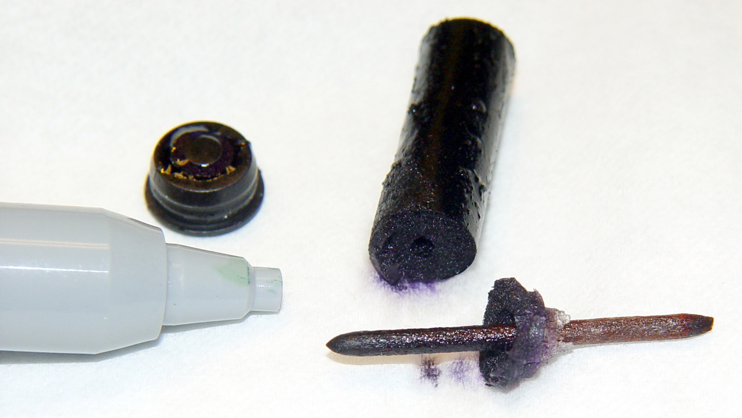
Dismantling the Koh-I-Noor black pen produced this unsightly mess:
HP 7475A – Koh-i-Noor black pen parts
I pushed the nib out of the shell using a pin punch, pretty thoroughly crushing the tip in the process. The ink reservoir looks like some sort of fluff inside a plastic sleeve, with a hole left by the butt end of the nib and a crust left by the evaporating ink. I scraped off the crust, put the nib in a cylinder filled with solvent, and let it sit for a few days, after which most of the black ink had vanished.
I reassembled the pen with the blunted end of the nib inside the body and the reservoir flipped end-for-end, in the hope that would work better.
Trying a different tactic with a Staedtlergreen pen, I removed the reservoir, filled the body with solvent, and dunked the tip in a solvent bath:
HP 7475A – Staedtler pen – nib soaking
After a few days, the body was still mostly full of solvent, so it’s not flowing freely through the nib. Perhaps leaving the nib in air would encourage the fluid to move outward, at the risk of drying the nib even more.
Pen 2, the gray K-I-N trace, seems a bit pallid, likely due to using cheap black inkjet ink. Apart from that, it’s continuous and presentable.
Pen 3, the green Staedtler, remains in the land of the undead; its ink flows better than before, but not enough to be worthwhile. The demo routine writes the annotation first and those characters came out well enouigh.
The other two pens also carry refilled ink: Pen 1 = ceramic tip, Pen 4 = Staedtler fiber (which, judging from the cap color, started out as gray and has become much darker after the inkjet ink refill).
All in all, a modest success and I’ll try again later. Better, however, to refill each pen before it dries out, as with the two “good” pens.
For reasons that aren’t relevant here, I had to reinforce some old basement stairs. Rather than drilling holes, sinking anchors, and installing screws, I just nailed painted 2×4 strips to the foundation using this Craftsman 1231.3817 Power Hammer, which is not available in a Sears / Kmart near you:
Sears Craftsman Power Hammer
It’s a handheld gun that drives two inches of hardened steel nail into solid concrete by firing what looks like an overstuffed 0.22 Short blank cartridge: load a nail, fit a cartridge, press the muzzle firmly against the target, and whack the butt end with a hammer.
Worked like a champ. Scary as you’d imagine.
If the nail stands proud of the surface, you can hit it again with a low(er) power load to drive it the rest of the way. Sometimes that sinks it below the surface, leaving a cylindrical pit. In the situations where I use this thing, nobody will ever notice.
It’s similar to the Remington Model 476 Powder Actuated Fastening Tool (manual), which you can get from Amazon and surely other vendors; fancier versions also exist. Equally surely, they’re illegal in some jurisdictions.
I have reason to use it every few decades, which is entirely enough for me…
Wear goggles, earplugs, gloves, and don’t get stupid.
Sticking an extruded plastic thread to the platform of a 3D printer requires absolutely accurate alignment and spacing, maybe ±0.05 mm across the entire platform. I’ll leave the topic of automatic alignment measurement & compensation for another day; here’s how to measure the actual platform alignment.
If the wall thickness (in the XY plane) doesn’t come out exactly right, fix that first by verifying the filament diameter setting, then adjusting the Extrusion Multiplier. If the extruder doesn’t produce the same wall thickness that the slicer calls for, you won’t get good results from anything else. In this case, they all have 0.40 mm thick walls, with 0.25 mm layers.
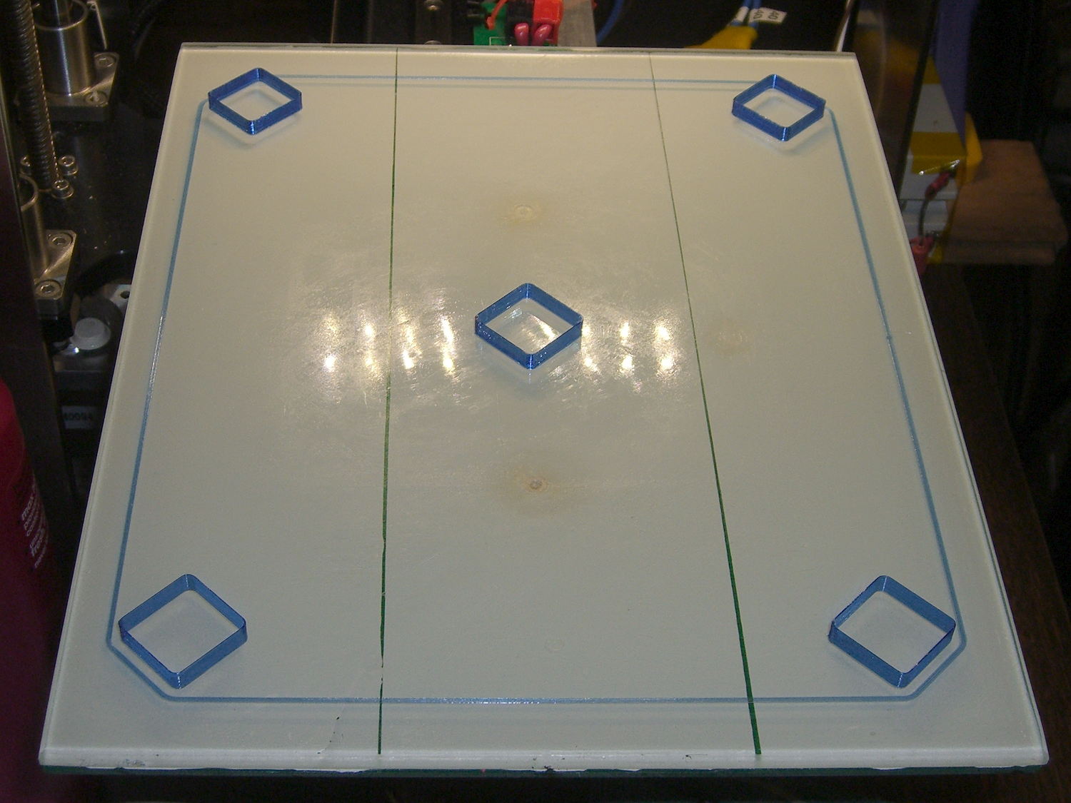
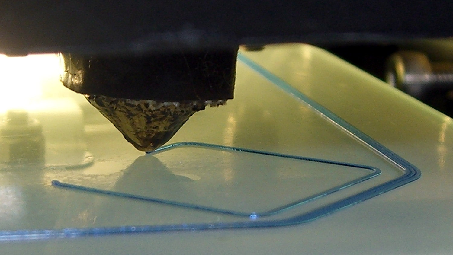
The first layer of all five boxes should be identical:
M2 V4 nozzle – thinwall box first layer
If the platform isn’t absolutely flat and properly aligned, those five first layers won’t be the same thickness. It’s surprisingly easy to spot differences under 0.05 mm, so pay attention to what’s happening.
When they’re done, pop them off and measure their actual height. I measure across adjacent sides, leaving the corners / stray hairs / snot out of the measurement, and figure the eyeballometric average of the values, which usually differ by less than ±0.03 mm. Write the height on the side to eliminate future angst:
Thinwall Box – platform height
The boxes should be 5.00 mm tall, so the leftmost box is short by -0.02 mm and the rightmost by -0.15 mm. The five boxes were 4.98, 4.95, 4.93, 4.92, and 4.85, with a mean of 4.93 mm. The variation across the 200×250 mm platform is 0.13 mm, which is pretty good.
Comparing the bottom layers of those boxes, the first layer of the 4.85 mm box is definitely squashed:
Thinwall Hollow Boxes – first layer bottom view – 4.98 4.85 mm
Once you know what to look for, it’s also obvious from the side (4.98 on the left, 4.85 on the right, bottom layers facing each other):
Thinwall boxes – 4.98 4.85 – bottom layers
Keep in mind that’s a difference of 0.13 mm = 130 µm, just over the ±0.05 mm I usually bandy about. The nominal layers are 0.25 mm = 250 µm.
A bit more magnification shows the nicely rounded first layer of the 4.98 mm box (rightmost thread of leftmost set):
Thinwall Box – 4.98 mm
And the squashed first layer of the 4.85 mm box (likewise):
Thinwall Box – 4.85 mm
Because the Z axis moves upward (on the M2, the platform moves downward) by exactly the layer thickness at the end of each layer, the first layer must absorb the entire difference between the desired thickness and the actual nozzle-to-platform distance. That squashed first layer is 0.10 mm thick, a bit less than half of the nominal 0.25 mm. The second layer of each box looks just like all the higher layers.
You can set the Z-axis offset for a very slight squish, with the maximum nozzle-to-platform distance at 0.25 mm and the minimum set by the other end of the total misalignment, because the plastic won’t adhere to the platform when the nozzle-to-platform distance exceeds the nozzle diameter.
Think of it this way: the plastic emerges from a 0.35 mm nozzle as a (slightly larger than) 0.35 mm cylinder that must squash to become a 0.25 mm high x 0.40 mm wide thread. Given the measurements above, setting the Z-axis home position to make the average box height equal to 5.00 mm would make the tallest box come out at 5.07 mm, which requires a 0.32 mm actual first layer that probably wouldn’t stick well at all.
When your printer can consistently produce five thinwall boxes with the proper wall thickness and height, then you can move on to more complex objects.