Ed Nisley's Blog: Shop notes, electronics, firmware, machinery, 3D printing, laser cuttery, and curiosities. Contents: 100% human thinking, 0% AI slop.
If you’re running Windows, then you have more experience than I do, but it seems Microsoft, for reasons best known to it, really really really wants you to upgrade to Windows 10, has been forcing nagware onto every Windows box in existence, and actively working to defeat efforts to remove said nagware.
Our Token Windows Box, an off-lease Dell Optiplex 780 that arrived bearing Windows 7 Professional, will never, ever get upgraded, because it’s running a bunch of ancient Windows programs that interface with specific bits of hardware, none of which (most likely) will work with Windows 10. In any event, I see no reason to go through the hassle of “upgrading” an old machine, (maybe) resolving all the inevitable compatibility problems, and (maybe) having no way to roll back the upgrade, all for a few programs run, at most, monthly.
Continually declining Windows 10 upgrade prompts isn’t my idea of a Good User Experience, but I’m also tired of manually inspecting and killing updates that re-re-re-install the nagware.
The GWX Control Panel (“GWX” = “Get Windows 10” in MS-speak) seems to be the least awful way of dealing with this mess. It’s not offered by Microsoft, for obvious reasons, but is offered free-of-charge.
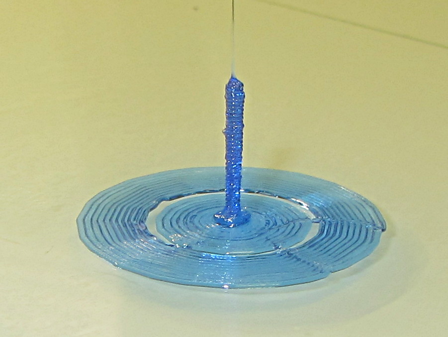
Sliced with Slic3r for PETG at 1 mm/s, with fans in full effect. It sits amid a 5 mm brim, inside a skirt that uses 15 mm of filament, giving it a Washington Monument aspect.
The challenge was to print a 0.7x9.0 cylinder, which doesn’t work well with a 0.35 mm nozzle. Instead, I went with 0.9 mm diameter. The result measures 1.1 mm over all the obvious bumps, so it’s surprisingly close. The “nail head” at the bottom most likely comes from the hot end depressurizing as it suddenly transitions from 15 mm/s in the brim to 1 mm/s for the cylinder.
Fairly obviously, you can’t print something like that at full speed (50 mm/s was claimed for a Rep 2 and I don’t believe that for an instant). Indeed, it’s such a pathological model that Slic3r’s minimum layer time and small perimeter settings had no effect; I had to manually set the extrusion speed to 1 mm/s in order to make it work. Plus adding that brim, because I knew it wouldn’t stand by itself.
Other than that, printing it was no big deal.
A picture from that M2 forum discussion suggests you can go crazy with this stuff:
All the tests are at 500 mA, approximately half the camera’s load. Oddly, the numeric values along the mA·h axis work out pretty close to the actual runtime in hours:
Sony – 1:30
Wasabi D – 1:15
Wasabi B – 0:40
Given that a typical bike ride takes an hour, the two year old Wasabi B battery’s 40 minute runtime isn’t useful. The Wasabi D battery is a bit over a year old and looks very much like the B battery did last year.
The Wasabi batteries march through the camera and charger in order, so each one gets used about once a week. The Sony battery gets used once every half-dozen complete cycles, just so I have a standard “good” battery.
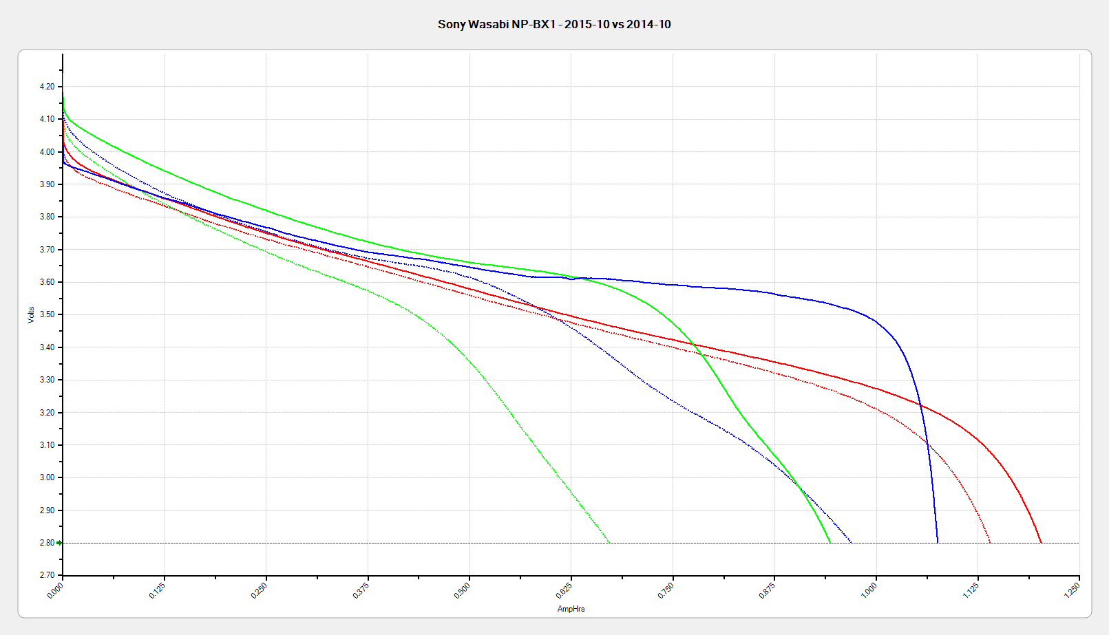
The Sony and Wasabi B cells over the course of two years:
Sony NP-BX1 – OEM Wasabi – 2015-10 2014-10 2014-01
Much to my surprise, the Wasabi batteries started out slightly better than the Sony OEM battery, at least as measured by the available voltage and energy. The camera runs from an internal switching power supply, so the area under the curve (basically equal to energy in W·h) above the cutoff voltage is all that matters.
In round numbers, I can expect 100 cycles out of each battery before the run time drops below the ride time; at $10/battery, that’s a dime a ride. Any claims that the batteries can be recharged “1000 times!” may be true, but they’ll have a useless fraction of their original capacity by then.
Back in the day, you could install a Genuine HP 09872-60066 Digitizing Sight in your Genuine HP 7475A plotter, maneuver the sight to an interesting point on the paper, press the Enter button, send the point’s coordinates through the serial port to the computer, then do whatever you like with the numbers.
Here in the future, I twiddled the demo code that draws Superformula patterns to send a digitization command and await the response at the end of each plot. I can then change the paper, press the Enter button, and get the next plot: exactly what I need for the upcoming Poughkeepsie Mini Maker Faire.
The only gotcha turns out to be that, having hacked the Chiplotle interface to use hardware handshaking, there’s no way to tell when the outgoing buffer has drained. Until that happens, the plotter can’t respond to the digitizing command and, eventually, Chiplotle kvetches about not hearing anything.
The least awful solution seems to be sleeping for 40 seconds (!) while the plotter trudges through the last line of the legend (!!), then continuing apace:
        print "Waiting for plotter... ignore timeout errors!"
        sleep(40)
        while NoneType is type(plt.status):
            sleep(5)

        print "Load more paper, then ..."
        print "  ... Press ENTER on the plotter to continue"
        plt.clear_digitizer()
        plt.digitize_point()

        plotstatus = plt.status
        while (NoneType is type(plotstatus)) or (0 == int(plotstatus) & 0x04):
            plotstatus = plt.status

        print "Digitized: " + str(plt.digitized_point)
When the interface times out, Chiplotle doesn’t set the status code to anything in particular (which makes sense), so you can’t do anything useful with it. Therefore, the operand order in the last while statement matters: you can’t convert a value of type NoneType into anything else.
The other change wraps the entire plotting loop with an always-and-forever loop: hit Ctrl-C to break out at the end of the day.
You can’t change the new plot’s paper size, because the digitizing command preempts the Enter button that’s part of the Enter+Size combination. That makes perfect sense, even in retrospect.
Testing that gave me the opportunity to run all the pens, refilled and OEM, through their paces:
As part of a discussion on the M2 forums about using rice to dehumidify 3D printer filament, I replaced the 500 g bag of silica gel in the basement safe with a bowl containing 200 g of long-grain brown rice from our rice supply and let it sit for a while:
Basement Safe Humidity – Rice vs. Silica Gel – 2015-10-31
The abrupt drop in humidity from 52% to the logger’s minimum 15% marks the point where I replaced the rice with a fresh bag of silica gel, with a door opening shortly thereafter. The basement air outside the safe varied between 52% and 54% during that time, so the air inside the safe trended upward toward that goal.
The rice still weighed exactly 200 g after its stay in the safe, so we can conclude it hadn’t absorbed or released any water.
Conclusion: nope, rice doesn’t work as a dehumidifier…
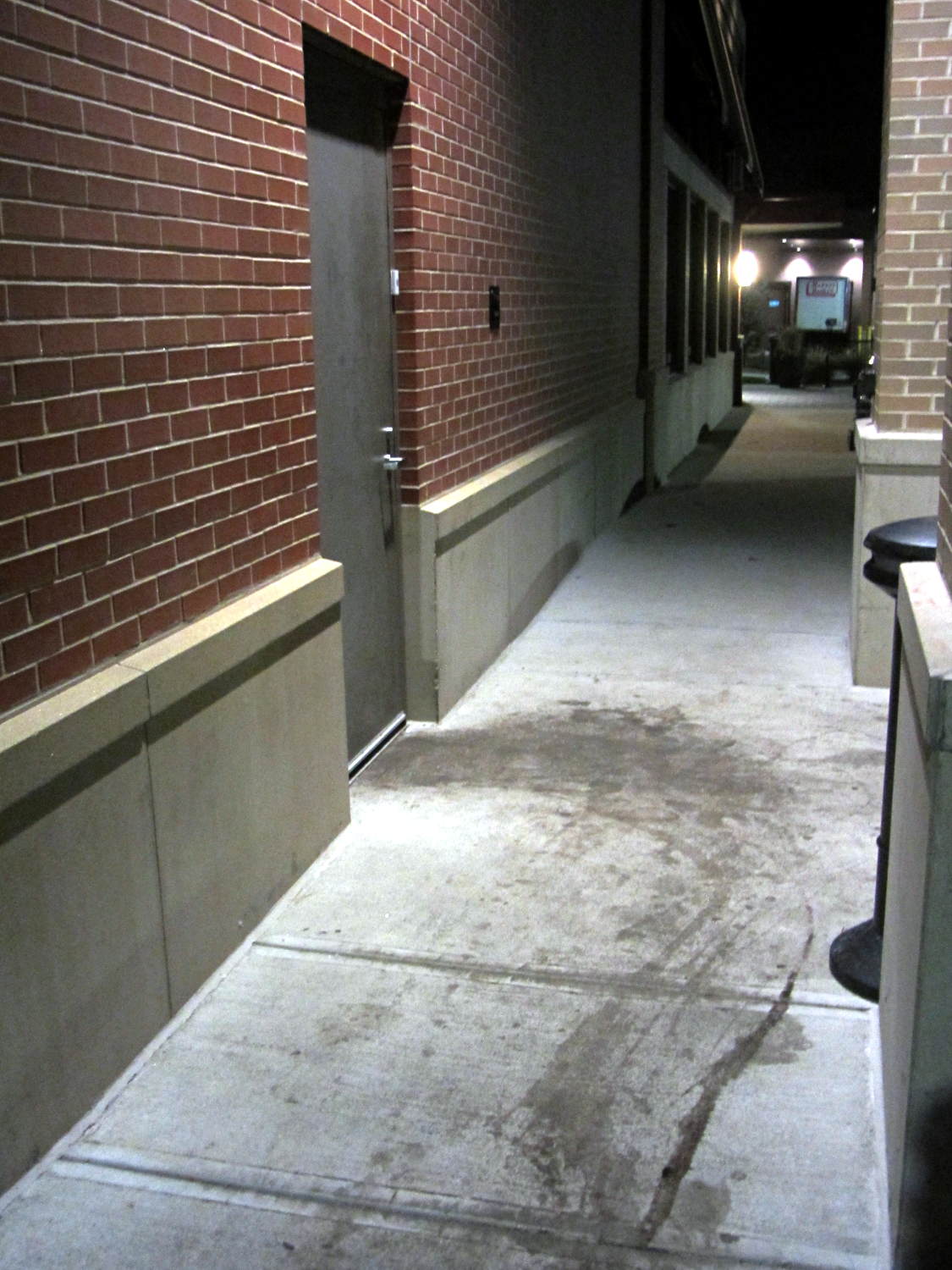
The stains appeared black-red under the cold LED light and my first thought went along the lines of “Somebody dragged a corpse out of the kitchen!”:
Restaurant back door
The dumpsters sit off the sidewalk behind me on the left, so, most likely, they just have a bit of trouble maneuvering overstuffed trash cans and grease tanks around the door. At least, that’s what we hoped.
Notice how the door hinges the wrong way? Perhaps the architect never anticipated moving waste from the kitchen to the dumpsters.
The food was OK (we did not order the Chef’s Special Long Pig), but their overly loud “background music” reverberated far too long inside a cavernous room with hard walls. We gave it 2/10: would not eat there again.
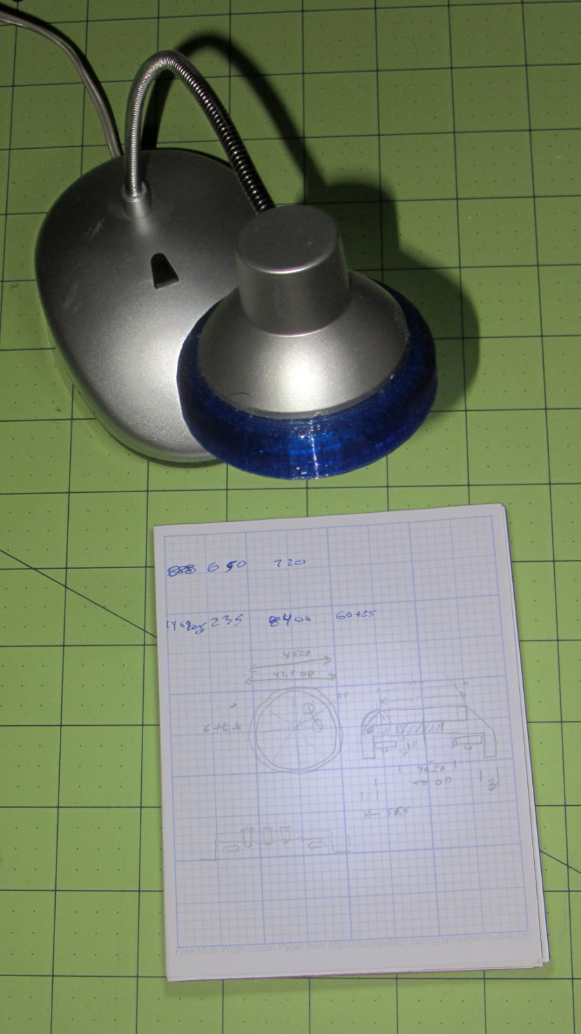
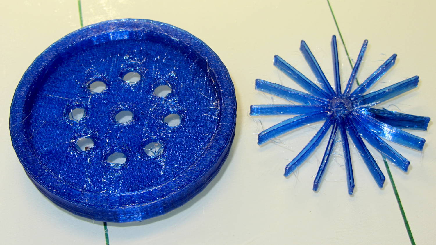
A defunct desk lamp emerged from the clutter and cried out for bright, new LEDs. This adapter puts a small LED ring and nine white LEDs on the original lamp head:
Ring Light Mount – in operation
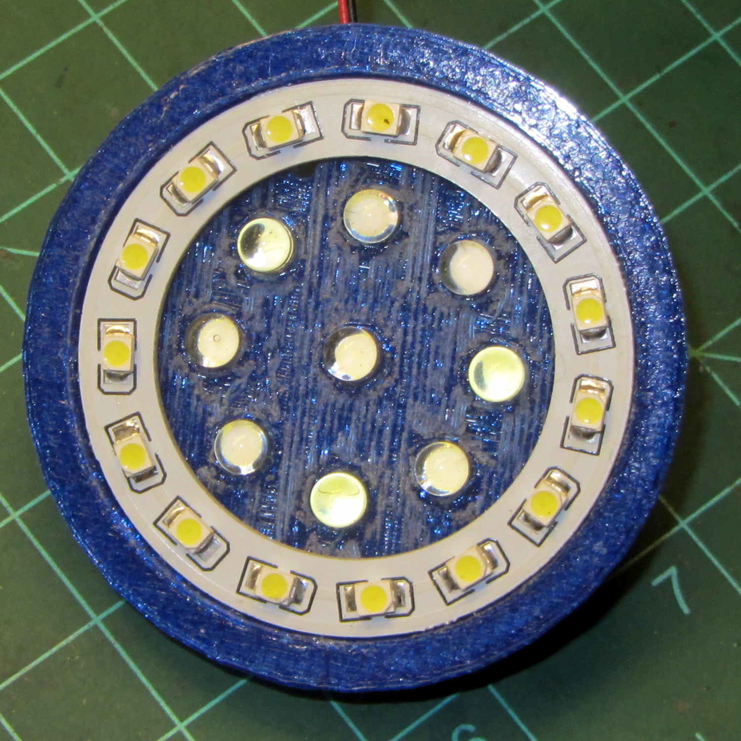
Peering into the business end, before mounting it on the lamp, shows some abrasive adjustment on the inside layer:
Ring Light Mount – LEDs installed
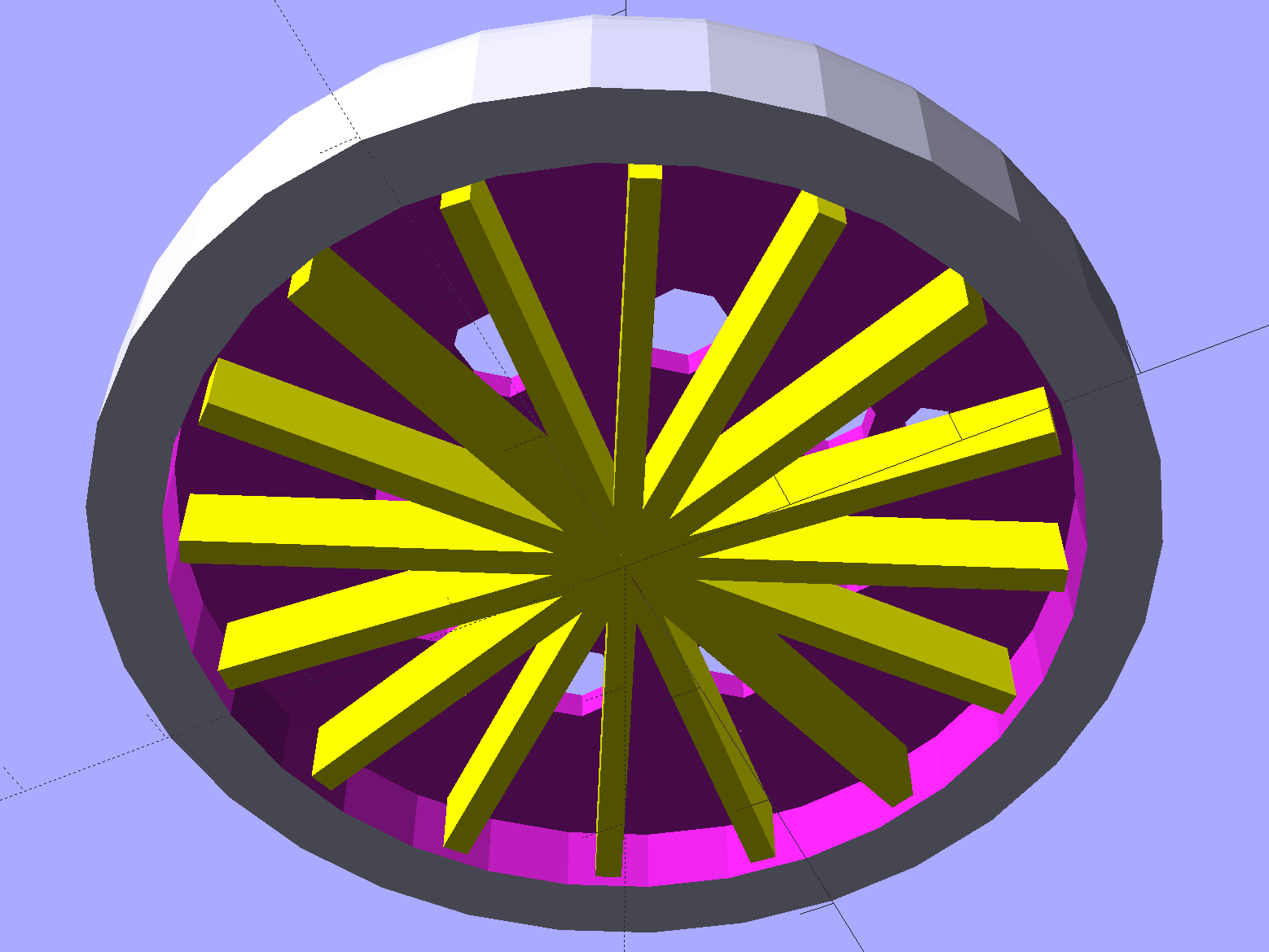
That layer printed over a quick-and-easy support spider:
Ring Light Mount – solid model – bottom
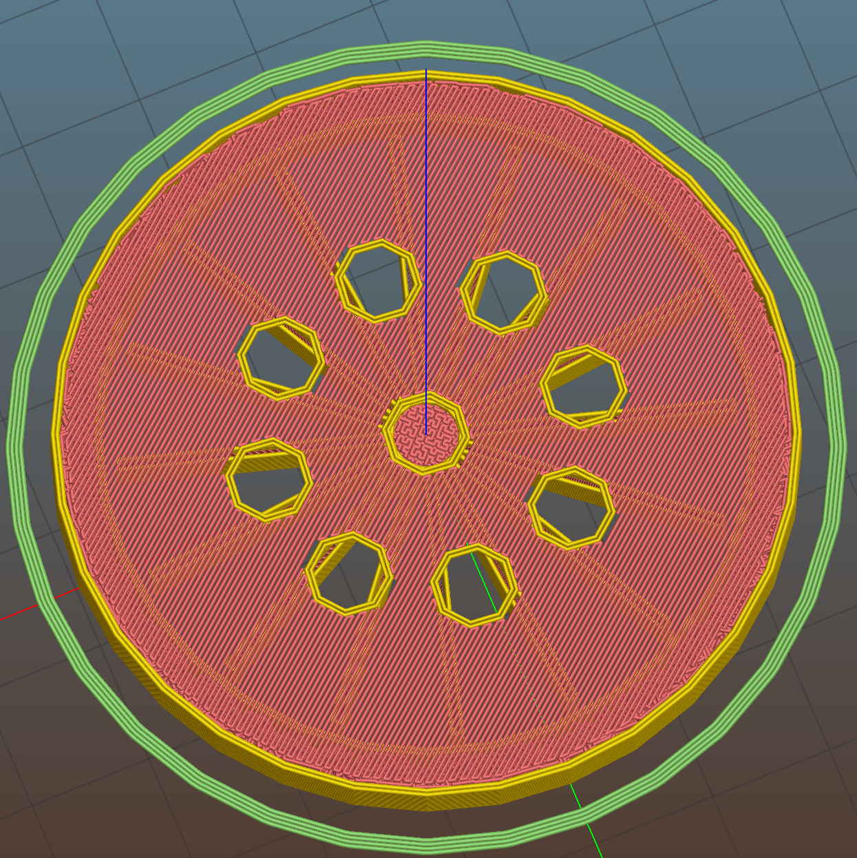
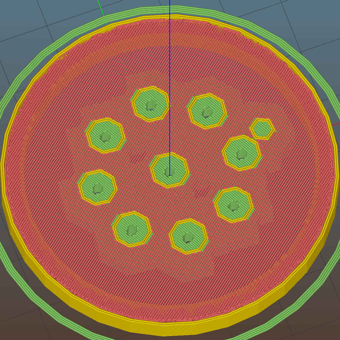
The Slic3r preview looking down through the layer just over the support shows that the perimeter of those LED holes doesn’t have much support:
Ring Light Mount – Slic3r preview – bridge layer
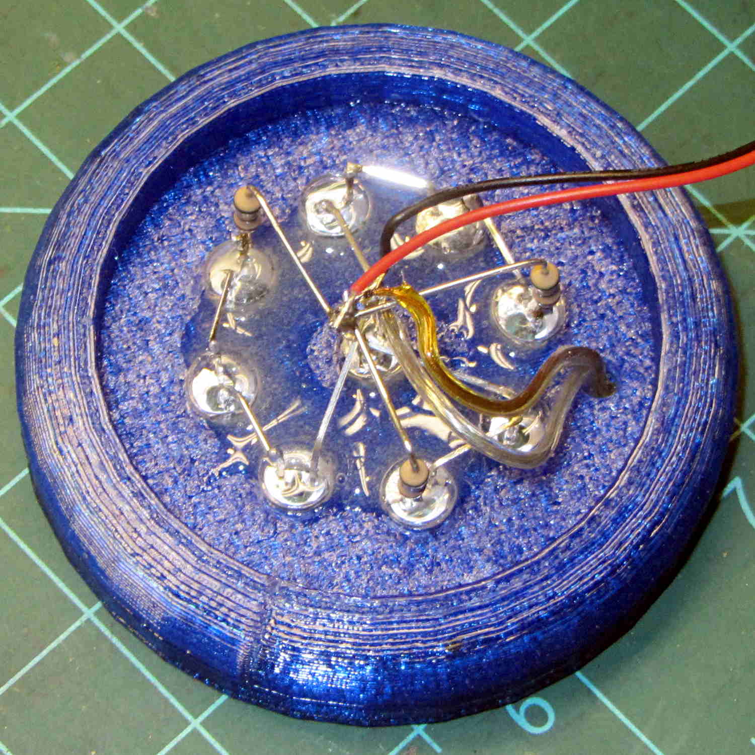
The obvious threads drooped in the predictable way, so I just clipped them off, sanded the high spots into submission, and epoxied everything in place:
Ring Light Mount – LED wiring
That nice Hilbert Curve infill is completely wasted inside the OEM shade, but the smooth curve around the rim had to be on the top surface.
Rather than beefing up the support, you should print the bottom ring (or the top rim) separately, then glue it back on, but I wanted to see how well simple support worked with PETG.
It came out reasonably well:
Ring Light Mount – support spider
That’s far more hair than usual, even for PETG, because I made the spider’s legs exactly three thread widths wide. Slic3r reduced the single infill thread to, literally, a hair that didn’t stick to the platform; the model now has four-thread-wide legs.
Slic3r’s automatic support would do a better job of holding up the underside, albeit with more plastic and printing time:
Ring Light Mount – Slic3r preview – auto support
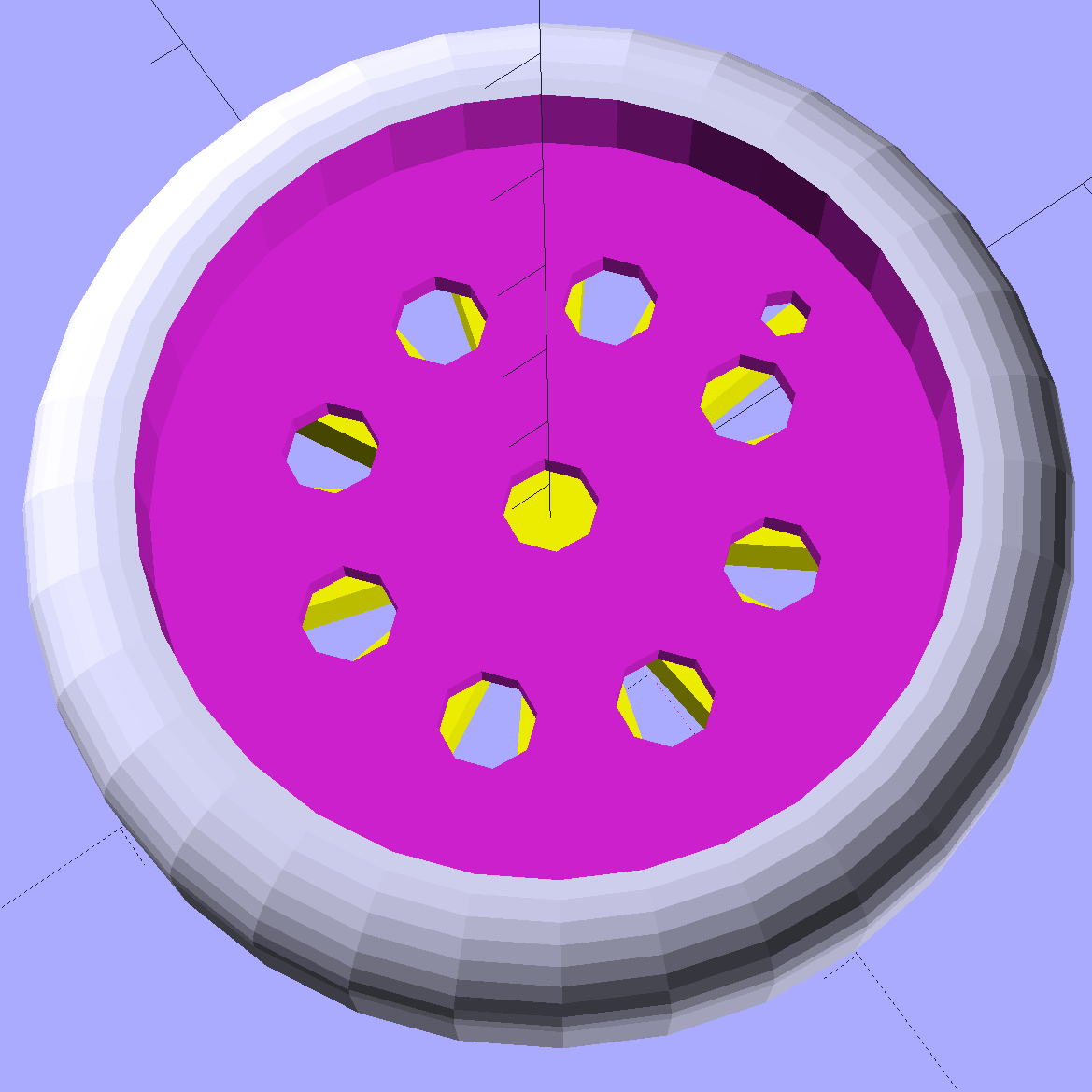
The top view looks about like you’d expect:
Ring Light Mount – solid model – top
Those two solid models show the small hole for the LED ring wiring, which I drilled into the as-printed plastic. The original layout included just the LED ring, with the wire through a big central hole, but then I realized the wall wart had enough moxie for a few more LEDs. So it goes.
Anyhow, the lamp provides just enough illumination below my big monitors to suffice. The gooseneck might not be quite long enough, but that’ll be another project…
The OpenSCAD source code:
// LED Ring Light Mount
// Ed Nisley KE4ZNU October 2015

DoSupport = true;

//- Extrusion parameters must match reality!

ThreadThick = 0.25;
ThreadWidth = 0.40;

HoleWindage = 0.2;

Protrusion = 0.1;			// make holes end cleanly

inch = 25.4;

function IntegerMultiple(Size,Unit) = Unit * ceil(Size / Unit);

//----------------------
// Dimensions

NumSides = 8*4;						// number of sides on each "cylinder"

LENGTH = 0;
ID = 1;
OD = 2;

Shade = [6.0,45.2,47.5];			// threaded end of OEM lamp shade
RingLED = [4.5,36.0,51.0];

SpotLED = [2.0,0,5.0];				// discrete LEDs in center
NumSpots = 8;						// discrete LEDs around the one in the middle

Support = [(RingLED[LENGTH] - 1*ThreadThick),0,(RingLED[OD] - 4*ThreadWidth)];
NumSupports = NumSides/2;

ThreadBase = RingLED[LENGTH] + SpotLED[LENGTH];
OAHeight = ThreadBase + Shade[LENGTH];

//----------------------
// Useful routines

module PolyCyl(Dia,Height,ForceSides=0) {			// based on nophead's polyholes

  Sides = (ForceSides != 0) ? ForceSides : (ceil(Dia) + 2);

  FixDia = Dia / cos(180/Sides);

  cylinder(r=(FixDia + HoleWindage)/2,
           h=Height,
	   $fn=Sides);
}

//----------------------
// Build it

	difference() {
		union() {																				// overall shape
			translate([0,0,ThreadBase])
				rotate_extrude(convexity = 2, $fn=NumSides)
					translate([Shade[OD]/2,0])
						circle(r=Shade[LENGTH],$fn=NumSides);
			cylinder(d=(Shade[OD] + 2*Shade[LENGTH]),h=ThreadBase,$fn=NumSides);
			translate([0,0,ThreadBase])
				cylinder(d=Shade[OD],h=Shade[LENGTH],$fn=NumSides);
		}

		translate([0,0,ThreadBase - Protrusion])
			cylinder(d=(Shade[ID] + HoleWindage),h=(Shade[LENGTH] + 2*Protrusion),$fn=NumSides);	// opening for shade thread

		translate([0,0,-Protrusion])
			cylinder(d=(RingLED[OD] + HoleWindage),h=(RingLED[LENGTH] + Protrusion),$fn=NumSides);	// opening for LED ring

		rotate(180/NumSides)																		// LED ring power wire
			translate([RingLED[ID]/2,0,0])
				rotate(180/6)
					PolyCyl(2.5,OAHeight,6);

		rotate(180/8  - 180/NumSides)
			PolyCyl(SpotLED[OD],OAHeight,8);														// central LED SpotLED

		for (i=[0:NumSpots-1])																		// surrounding spots
			rotate(i*360/NumSpots - 180/NumSides)
				translate([(RingLED[ID] - 2*SpotLED[OD])/2,0,0])
						rotate(180/8)
							PolyCyl(SpotLED[OD],OAHeight,8);
	}

//-- Support structure

	if (DoSupport)
		color("Yellow")
		rotate(180/NumSides)													// align bars to flat internal faces
			for (i=[0:NumSupports/2 - 1]) {
				rotate(i * 360 / NumSupports)
					translate([0,0,Support[LENGTH]/2])
						cube([Support[OD],4*ThreadWidth,Support[LENGTH]],center=true);
			}