The Smell of Molten Projects in the Morning

Ed Nisley's Blog: Shop notes, electronics, firmware, machinery, 3D printing, laser cuttery, and curiosities. Contents: 100% human thinking, 0% AI slop.

Author: Ed

  • Microscope Stage Positioner

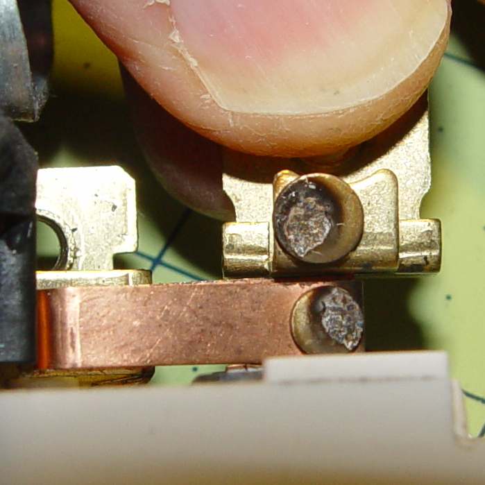
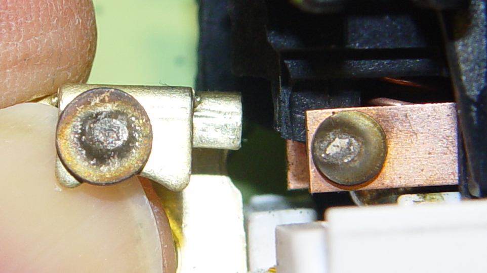
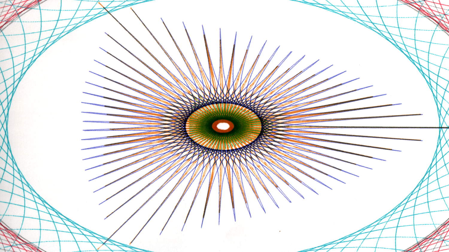
    Given the vanishingly small depth of field provided by a cheap USB camera peering through the stereo zoom microscope, I’ve always wanted a better way of moving objects by small increments. The rehabilitated micropositioner didn’t have the right orientation or end effector:

    Micropositioner
    Micropositioner

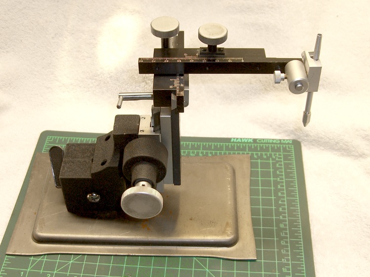
    So I rearranged the axis slides and added a small table:

    Microscope Stage Positioner
    Microscope Stage Positioner

    That frees up the magnetic base and husky angle bracket, plus a few odds & ends, for future adventures.

    The clear base is a random chunk of acrylic, bandsawed to the proper length, then tediously squared and drilled on the Sherline:

    Microscope Stage Positioner - base squaring
    Microscope Stage Positioner – base squaring

    I briefly thought of printing the base, but came to my senses: there are better ways to make big flat surfaces.

    The little aluminum table has a nubbly spray coating that came straight from the heap and looks surprisingly good after squaring & drilling. The X axis block puts it below the platform and one screw head above the desk when the Y axis arm sits flat on the acrylic base.

    One solid model view arranges things in more-or-less the proper layout to check the alignment:

    Microscope Stage Positioner - solid model - Show layout
    Microscope Stage Positioner – solid model – Show layout

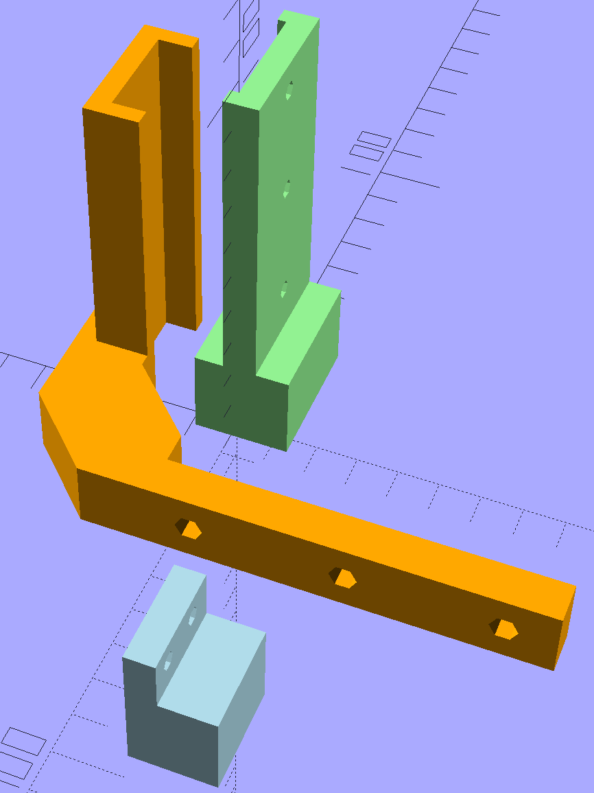
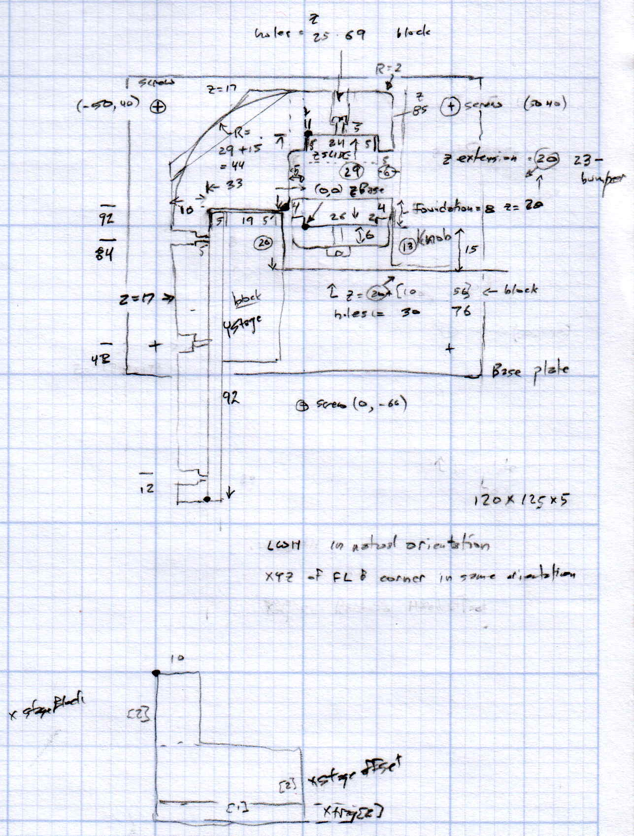
    The build layout reduces the platform space:

    Microscope Stage Positioner - Slic3r preview
    Microscope Stage Positioner – Slic3r preview

    You’re looking at four hours of PETG print time at 0.2 mm layer thickness with 15% infill and Hilbert Curve surfaces.

    All of the screws have UNF fine-pitch threads (4-48, 6-40, 8-36, stuff like that), so the solid model includes the spacing required to reuse the original screws: those big holes in the Y axis arm end in little clearance holes for the tiny screws. Some of the screws bottom out with barely two millimeters of thread engagement in the slides, while others could jam against the racks. I didn’t want to cut that many screws from my Brownell’s gun screw assortment unless I absolutely had to. So far, so good.

    I spent quite a while doodling the layout to convince myself that it would actually work:

    Microscope Stage Positioner - layout doodle
    Microscope Stage Positioner – layout doodle

    Memo to self: Next time, use a larger scale!

    Although the whole lashup works as intended, those metal hunks are way too heavy for the plastic block that fits between the Z axis drive pillar and the X axis slide: that long Y axis arm drooped toward the front by about 5 mm. A small shim raised the front of the Z axis footprint enough to level the arm, but I think the right answer is a metal upright with a bigger footprint that spreads the load.

    All that mass hanging out in mid-air turns the plastic pieces into springs: you can’t keep your fingers on the knobs. Fortunately, everything returns to the same position after you release the knob, so it’s easy to move in precise increments if you close your eyes until the view settles down.

    There’s a reason optical equipment uses cast iron, steel, and brass… but I’ll settle for plastic.

    The OpenSCAD source code as a GitHub gist:

    // Microscope Stage Positioner
    // Ed Nisley KE4ZNU January 2016
    Layout = "Build"; // Show Build
    // Base ZStand YMount XMount
    Gap = 0.0;
    //- Extrusion parameters must match reality!
    ThreadThick = 0.25;
    ThreadWidth = 0.40;
    HoleWindage = 0.2;
    Protrusion = 0.1; // make holes end cleanly
    inch = 25.4;
    function IntegerMultiple(Size,Unit) = Unit * ceil(Size / Unit);
    //———————-
    // Dimensions
    SlipFit = 0.1;
    ZDrive = [26.0,19.6,75.0]; // stationary part of Z drive
    ZDriveOffset =[0,0,22.0]; // left front corner of stationary Z base
    ZWall = 4.0; // thickness of edge wrapped around Z columns
    YStageBlock = [25.0,61.0,17.0]; // Y stage mount + slide
    YStageOffset = [-6.0,4.0,0.0]; // offset to inner corner of Y stage holder
    YArm = [10.0,93.0,17.0]; // mount to stationary part of Y stage
    ZStage = [24.0,9.7,85.0]; // moving part of Z drive
    ZYArm = [(2*ZWall + ZStage[0]),10.0,YArm[2]]; // attaches to ZStage, same thickness as YArm
    XStageBlock = [25.0,20.0,12.0]; // X stage mount + slide
    XStageOffset = [-95.0,-15.0,-26]; // offset to rear left bottom corner of X stage slide
    XTray = [25,25,5]; // X tray attached to bottom of X mount
    //———————-
    // Useful routines
    module PolyCyl(Dia,Height,ForceSides=0) { // based on nophead's polyholes
    Sides = (ForceSides != 0) ? ForceSides : (ceil(Dia) + 2);
    FixDia = Dia / cos(180/Sides);
    cylinder(r=(FixDia + HoleWindage)/2,
    h=Height,
    $fn=Sides);
    }
    //– Z Stand
    module ZStand() {
    Holes = [12.0,41.5,68.0];
    HoleOD = 3.5;
    HolesOC = 15.0;
    echo(str("Z Stand holes OC: ",HolesOC));
    ZPlate = 6.0; // thickness of Z plate = max screw grab distance
    ZStandWrap = 2.0; // length of edge wrapped around Z column
    MaxY = 9.0;
    MinY = -14.0;
    difference() {
    union() {
    linear_extrude(height=ZDriveOffset[2])
    polygon(points=[
    [-ZWall,MaxY], // limited by Z slide rack
    [ZDrive[0] + ZWall,MaxY],
    [ZDrive[0] + ZWall,MinY], // limited by X slide rack
    [-ZWall,MinY]
    ]);
    linear_extrude(height=(ZDrive[2] + ZDriveOffset[2]),convexity=4)
    polygon(points=[
    [-SlipFit,0],
    [ZDrive[0] + SlipFit,0.0],
    [ZDrive[0] + SlipFit,ZStandWrap],
    [ZDrive[0] + ZWall,ZStandWrap],
    [ZDrive[0] + ZWall,-ZPlate],
    [-ZWall,-ZPlate],
    [-ZWall,ZStandWrap],
    [-SlipFit,ZStandWrap]
    ]);
    }
    for (i = [0:len(Holes) – 1]) // holes along Z stand
    translate([ZDrive[0]/2,ZDrive[1]/2,(Holes[i] + ZDriveOffset[2])])
    rotate([90,0,0])
    PolyCyl(HoleOD,ZDrive[1]);
    for (i = [-1,1]) // mounting screw holes
    translate([i*HolesOC/2 + ZDrive[0]/2, // center the holes from side to side
    (MaxY + MinY)/2, // moby hack to put holes on midline
    -Protrusion])
    PolyCyl(3.5,0.75*ZDriveOffset[2],6);
    }
    }
    //– Y Mounting arm
    // Polygon origin at inner corner nearest the Z stand column
    module YMount() {
    YHoles = [12.0,48.0,84.0]; // mounting holes along Y stage arm, from outside in
    YScrewLength = 4.0; // screw head to Y stage mount
    ZStageBase = [(ZDrive[0] – ZStage[0])/2,(ZDrive[1] + ZStage[1]),0.0] – YStageOffset; // local coordinates of Z slide left rear corner
    ZHoles = [26.5,55.0,71.0];
    ZStageWrap = 8.0; // length of edge wrapped around Z stage
    Trim = ZStageBase[1] – ZStageWrap;
    union() {
    difference() {
    linear_extrude(height=YArm[2],convexity=5)
    polygon(points=[
    [-Trim,0.0],
    [-YStageBlock[0],0.0],
    [-YStageBlock[0],-(YArm[1] + SlipFit)],
    [-(YStageBlock[0] + YArm[0]),-(YArm[1] + SlipFit)],
    [-(YStageBlock[0] + YArm[0]),Trim],
    [-Trim,(ZStageBase[1] + ZYArm[1])],
    [(ZStageBase[0] + ZStage[0]/2),(ZStageBase[1] + ZYArm[1])],
    [(ZStageBase[0] + ZStage[0] + ZWall),(ZStageBase[1] + 0*ZYArm[1])],
    [(ZStageBase[0] + ZStage[0] + ZWall),(ZStageBase[1] – ZStageWrap)],
    [(ZStageBase[0] + ZStage[0] + SlipFit),(ZStageBase[1] – ZStageWrap)],
    [(ZStageBase[0] + ZStage[0] + SlipFit),ZStageBase[1]],
    [(ZStageBase[0] – SlipFit),ZStageBase[1]],
    [(ZStageBase[0] – SlipFit),(ZStageBase[1] – ZStageWrap)],
    [0.0,(ZStageBase[1] – ZStageWrap)],
    [0.0,Trim]
    ]);
    for (j=[0:len(YHoles) – 1]) { // Y stage mounting screws
    translate([-(YStageBlock[0] + YScrewLength),
    (-YArm[1] + YHoles[j] – 2*SlipFit),
    YArm[2]/2])
    rotate([0,-90,0]) rotate(180/6)
    PolyCyl(5.5,YArm[0],6);
    translate([-(YStageBlock[0] – Protrusion),
    (-YArm[1] + YHoles[j] – 2*SlipFit),
    YArm[2]/2])
    rotate([0,-90,0]) rotate(180/6)
    PolyCyl(2.5,2*YArm[0],6);
    }
    }
    if (true)
    difference() {
    linear_extrude(height=ZStage[2],convexity=5)
    polygon(points=[
    [(ZStageBase[0] – ZWall),(ZStageBase[1] + 5.0)],
    [(ZStageBase[0] + ZStage[0] + ZWall),(ZStageBase[1] + 5.0)],
    [(ZStageBase[0] + ZStage[0] + ZWall),(ZStageBase[1] – ZStageWrap)],
    [(ZStageBase[0] + ZStage[0] + SlipFit),(ZStageBase[1] – ZStageWrap)],
    [(ZStageBase[0] + ZStage[0] + SlipFit),ZStageBase[1]],
    [(ZStageBase[0] – SlipFit),ZStageBase[1]],
    [(ZStageBase[0] – SlipFit),(ZStageBase[1] – ZStageWrap)],
    [(ZStageBase[0] – ZWall),(ZStageBase[1] – ZStageWrap)],
    ]);
    for (k=[0:len(ZHoles) – 1])
    translate([(ZStageBase[0] + ZStage[0]/2),0.0,ZHoles[k]])
    rotate([-90,0,0])
    PolyCyl(3.5,2*ZStageBase[1],6);
    }
    }
    }
    //– X Slide attachment
    // Origin at left rear bottom of mount
    module XMount() {
    XHoles = [6.0,18.0]; // from end of X slide
    XHolesOffset = 7.0; // from bottom of X slide
    TrayHolesOC = 10.0;
    echo(str("Tray holes OC: ",TrayHolesOC));
    BlockOAH = XStageBlock[2] – XStageOffset[2] – XTray[2]; // overall height of mount
    difference() {
    translate([XStageBlock[0],0,BlockOAH])
    rotate([0,90,180])
    linear_extrude(height=XStageBlock[0],convexity=2)
    polygon(points=[
    [0,0],
    [0.0,7.0],
    [(XStageBlock[2] + SlipFit),7.0],
    [(XStageBlock[2] + SlipFit),XStageBlock[1]],
    [BlockOAH,XStageBlock[1]],
    [BlockOAH,0.0],
    ]);
    for (i=[0:len(XHoles) – 1]) // holes for X stage screws
    translate([XHoles[i],Protrusion,BlockOAH – XStageBlock[2] + XHolesOffset])
    rotate([90,0,0])
    PolyCyl(3.5,2*7.0,6);
    for (i=[-1,1]) // holes for tray mount
    translate([i*TrayHolesOC/2 + XStageBlock[0]/2,-XStageBlock[1]/2,-Protrusion])
    PolyCyl(2.5,0.75*(BlockOAH – XStageBlock[2]),6);
    }
    }
    //———————-
    // Build it
    if (Layout == "ZStand")
    ZStand();
    if (Layout == "YMount")
    YMount();
    if (Layout == "XMount")
    XMount();
    if (Layout == "Show") {
    color("lightgreen")
    ZStand();
    color("orange")
    translate(YStageOffset)
    YMount();
    color("lightblue")
    translate(XStageOffset + [0,0,-XStageOffset[2]])
    XMount();
    }
    if (Layout == "Build") {
    translate([20,0,0])
    ZStand();
    translate([YStageBlock[0]/2,0,0])
    YMount();
    translate([20,-30,0])
    XMount();
    }
  • Great Blue Heron at Red Oaks Mill Dam

    A Great Blue Heron kept watch over us from the decaying spillway as we walked along on Old Mill Road:

    Heron at Red Oaks Mill Dam - spillway
    Heron at Red Oaks Mill Dam – spillway

    A mid-stream perch provided a better vantage point:

    Heron at Red Oaks Mill Dam - midstream
    Heron at Red Oaks Mill Dam – midstream

    The concrete slab in the lower right corner came from the dam breast.

    The camera never lies, but if you could look upward just a bit, you’d see the unending stream of cars passing by on Red Oaks Mill Road at the Rt 376 intersection …

  • Bathroom Light Switch: Contact Autopsy

    The dual switch controlling the bathroom lights began requiring some fiddling, which was not to be tolerated. After replacing the switch, I cracked the old one open to see what’s inside…

    The failed side of the switch controlled the lights over the sink:

    Light switch contacts - lights
    Light switch contacts – lights

    The side for the ceiling vent fan + light got much less use, still worked, and look a bit less blasted.

    Light switch contacts - ceiling fan
    Light switch contacts – ceiling fan

    Not much to choose between the two. It’s been running for nigh onto two decades, so …

  • Monthly Image: Hawk Overhead

    We often see a hawk perched atop a street lamp along Hooker Avenue, but this is the closest we’ve come:

    This slideshow requires JavaScript.

    That first wingbeat must be exhilarating:

    Hawk on Hooker 2015-12-26 - detail - 0236
    Hawk on Hooker 2015-12-26 – detail – 0236
    Hawk on Hooker 2015-12-26 - detail - 0248
    Hawk on Hooker 2015-12-26 – detail – 0248

    There doesn’t seem to be much behind the notion of reincarnation, but one interation as a bird would be edifying…

  • Ham It Up Noise Source

    An RTL-SDR receiver & Ham It Up RF upconverter arrived, with the intent of poking at LF signals. The upconverter circuit board also contains a mostly populated RF noise source:

    Ham-It-Up v1.3 noise source - schematic
    Ham-It-Up v1.3 noise source – schematic

    Being a sucker for noise sources, I spent some time pondering the circuitry.

    The as-built board has a 0 Ω jumper instead of the 6 dB pad along the upper right edge:

    Ham-It-Up v1.3 - noise components
    Ham-It-Up v1.3 – noise components

    The previous version had a pi bandpass filter in place of the pad and you could certainly repopulate it with two caps and a teeny inductor if you so desired.

    I added the SMA connector, which isn’t quite identical to the IF output connector above it:

    Ham-It-Up v1.3 - noise SMA
    Ham-It-Up v1.3 – noise SMA

    That will require a new hole in the end plate that I’ll get around to shortly. It also needs an external switch connected to the Enable jumper, but that’s in the nature of fine tuning.

    I’m awaiting a handful of adapters & cables from halfway around the planet…

  • Olfa Rotary Cutter Spacer

    At some point along the way, the bright yellow washer (they call it a “spacer”) on Mary’s 60 mm Olfa rotary cutter went missing. A casual search suggests that replacement washers come directly from Olfa after navigating their phone tree, but …

    Judging from scuffs on the rear surface, the washer serves two purposes:

    • Hold the blade close to the handle against slightly misaligned cutting forces
    • Add more compression to the wave washer under the nut

    This model is much more intricate than the stock washer:

    Olfa Rotary Cutter - backing washer
    Olfa Rotary Cutter – backing washer

    The trench across the middle of the thicker part allows a wider compression adjustment range for the wave washer and provides more thread engagement at the lightest setting for my liking. The shape comes from the chord equation based on measurements of the wave washer:

    Olfa Rotary Cutter - washer doodles
    Olfa Rotary Cutter – washer doodles

    The wave washer keys on the bolt flats: the whole affair rotates with the blade and gives the nut no inclination to unscrew. If you remove the trench, the remaining hole has the proper shape to key on the bolt and rotate with it; with the trench in place, the wave washer’s sides haul the plastic washer along with it.

    The plain ring, just two threads thick, glues bottom-to-bottom on the thicker part to soak up the air gap and provide more blade stability. It’s not entirely clear that’s a win; it’s easy to omit.

    It looks about like you’d expect:

    Olfa Rotary Cutter - washer in place
    Olfa Rotary Cutter – washer in place

    The wave washer must go on the bolt with the smooth curve downward into the trench. That orientation that wasn’t enforced by the Official Olfa spacer washer’s smooth sides.

    The nut sits upside-down to show the face that normally sits against the wave washer. I’d lay long odds that the recess around the threads originally held a conical compression spring with a penchant for joining the dust bunnies under the sewing table. You can insert the wave washer the wrong way, but it doesn’t store enough energy to go airborne unless you drop it, which did happen once with the expected result.

    The OpenSCAD source code as a GitHub gist:

    // Olfa rotary cutter backing washer
    // Ed Nisley KE4ZNU January 2016
    Layout = "Build";
    //- Extrusion parameters must match reality!
    // Print with +1 shells and 3 solid layers
    ThreadThick = 0.20;
    ThreadWidth = 0.40;
    HoleWindage = 0.2;
    function IntegerMultiple(Size,Unit) = Unit * ceil(Size / Unit);
    Protrusion = 0.1; // make holes end cleanly
    //———————-
    // Dimensions
    WasherOD = 35.0;
    WasherThick = 1.5;
    WaveOD = 14.0; // wave washer flat dia
    WaveM = 1.8; // height of wave washer bend
    BendRad = (pow(WaveM,2) + pow(WaveOD,2)/4) / (2*WaveM); // radius of wave washer bend
    echo(str("Wave washer bend radius: ",BendRad));
    SpacerID = WaveOD + 2.0;
    SpacerThick = 2*ThreadThick;
    NumSides = 12*4;
    $fn = NumSides;
    //———————-
    // Useful routines
    module PolyCyl(Dia,Height,ForceSides=0) { // based on nophead's polyholes
    Sides = (ForceSides != 0) ? ForceSides : (ceil(Dia) + 2);
    FixDia = Dia / cos(180/Sides);
    cylinder(r=(FixDia + HoleWindage)/2,
    h=Height,
    $fn=Sides);
    }
    //———————-
    // Parts
    module Upper() {
    difference() {
    cylinder(d1=WasherOD,d2=(WasherOD – 2.0),h=WasherThick);
    translate([0,0,-Protrusion])
    intersection() {
    PolyCyl(8.2,2.0,8);
    cube([(6.0 + HoleWindage),10,2*WasherThick],center=true);
    }
    translate([-(WaveOD + 1.0)/2,0,BendRad])
    rotate([0,90,0]) rotate(0*180/16)
    PolyCyl(BendRad*2,(WaveOD + 1),16);
    }
    }
    module Spacer() {
    difference() {
    cylinder(d=WasherOD,h=SpacerThick);
    translate([0,0,-Protrusion])
    cylinder(d=SpacerID,h=2*SpacerThick);
    }
    }
    //———————-
    // Build it!
    if (Layout == "Show") {
    translate([0,0,SpacerThick])
    color("Cyan")
    Upper();
    color("LightCyan")
    Spacer();
    }
    if (Layout == "Build") {
    translate([-0.6*WasherOD,0,0])
    Upper();
    translate([0.6*WasherOD,0,0])
    Spacer();
    }
  • HP 7475A: Superformula Successes

    In the course of running off some Superformula plots, I found what must be my original stash of B-size plotter paper. Although it wasn’t archival paper and has yellowed a bit with age, it’s the smoothest and creamiest paper I’ve touched in quite some time: far nicer than the cheap stuff I picked up while reconditioning the HP 7475A plotter & its assorted pens.

    Once in a while, all my errors and omissions cancel out enough to produce interesting results on that historic paper, hereby documented for future reference…

    A triangle starburst:

    Superformula - triangle burst
    Superformula – triangle burst
    Superformula - triangle burst - detail
    Superformula – triangle burst – detail

    A symmetric starburst:

    Superformula - starburst
    Superformula – starburst
    Superformula - starburst - detail
    Superformula – starburst – detail

    Complex meshed ovals:

    Superformula - meshed ovals
    Superformula – meshed ovals
    Superformula - meshed ovals - details
    Superformula – meshed ovals – details

    They look better in person, of course. Although inkjet printers produce more accurate results in less time, those old pen plots definitely look better in some sense.

    The demo program lets you jam a fixed set of parameters into the plot, so (at least in principle) one could reproduce a plot from the parameters in the lower right corner. Here you go:

    The triangle starburst:

    Superformula - triangle burst - parameters
    Superformula – triangle burst – parameters

    The symmetric starburst:

    Superformula - starburst - parameters
    Superformula – starburst – parameters

    The meshed ovals:

    Superformula - meshed ovals - parameters
    Superformula – meshed ovals – parameters

    The current Python / Chiplotle source code as a GitHub gist:

    from chiplotle import *
    from math import *
    from datetime import *
    from time import *
    from types import *
    import random
    def superformula_polar(a, b, m, n1, n2, n3, phi):
    ''' Computes the position of the point on a
    superformula curve.
    Superformula has first been proposed by Johan Gielis
    and is a generalization of superellipse.
    see: http://en.wikipedia.org/wiki/Superformula
    Tweaked to return polar coordinates
    '''
    t1 = cos(m * phi / 4.0) / a
    t1 = abs(t1)
    t1 = pow(t1, n2)
    t2 = sin(m * phi / 4.0) / b
    t2 = abs(t2)
    t2 = pow(t2, n3)
    t3 = -1 / float(n1)
    r = pow(t1 + t2, t3)
    if abs(r) == 0:
    return (0, 0)
    else:
    # return (r * cos(phi), r * sin(phi))
    return (r, phi)
    def supershape(width, height, m, n1, n2, n3,
    point_count=10 * 1000, percentage=1.0, a=1.0, b=1.0, travel=None):
    '''Supershape, generated using the superformula first proposed
    by Johan Gielis.
    – `points_count` is the total number of points to compute.
    – `travel` is the length of the outline drawn in radians.
    3.1416 * 2 is a complete cycle.
    '''
    travel = travel or (10 * 2 * pi)
    # compute points…
    phis = [i * travel / point_count
    for i in range(1 + int(point_count * percentage))]
    points = [superformula_polar(a, b, m, n1, n2, n3, x) for x in phis]
    # scale and transpose…
    path = []
    for r, a in points:
    x = width * r * cos(a)
    y = height * r * sin(a)
    path.append(Coordinate(x, y))
    return Path(path)
    # RUN DEMO CODE
    if __name__ == '__main__':
    override = False
    plt = instantiate_plotters()[0]
    # plt.write('IN;')
    if plt.margins.soft.width < 11000: # A=10365 B=16640
    maxplotx = (plt.margins.soft.width / 2) – 100
    maxploty = (plt.margins.soft.height / 2) – 150
    legendx = maxplotx – 2900
    legendy = -(maxploty – 750)
    tscale = 0.45
    numpens = 4
    # prime/10 = number of spikes
    m_values = [n / 10.0 for n in [11, 13, 17, 19, 23]]
    # ring-ness 0.1 to 2.0, higher is larger
    n1_values = [
    n / 100.0 for n in range(55, 75, 2) + range(80, 120, 5) + range(120, 200, 10)]
    else:
    maxplotx = plt.margins.soft.width / 2
    maxploty = plt.margins.soft.height / 2
    legendx = maxplotx – 3000
    legendy = -(maxploty – 900)
    tscale = 0.45
    numpens = 6
    m_values = [n / 10.0 for n in [11, 13, 17, 19, 23, 29, 31,
    37, 41, 43, 47, 53, 59]] # prime/10 = number of spikes
    # ring-ness 0.1 to 2.0, higher is larger
    n1_values = [
    n / 100.0 for n in range(15, 75, 2) + range(80, 120, 5) + range(120, 200, 10)]
    print " Max: ({},{})".format(maxplotx, maxploty)
    # spiky-ness 0.1 to 2.0, higher is spiky-er (mostly)
    n2_values = [
    n / 100.0 for n in range(10, 60, 2) + range(65, 100, 5) + range(110, 200, 10)]
    plt.write(chr(27) + '.H200:') # set hardware handshake block size
    plt.set_origin_center()
    # scale based on B size characters
    plt.write(hpgl.SI(tscale * 0.285, tscale * 0.375))
    # slow speed for those abrupt spikes
    plt.write(hpgl.VS(10))
    while True:
    # standard loadout has pen 1 = fine black
    plt.write(hpgl.PA([(legendx, legendy)]))
    pen = 1
    plt.select_pen(pen)
    plt.write(hpgl.PA([(legendx, legendy)]))
    plt.write(hpgl.LB("Started " + str(datetime.today())))
    if override:
    m = 4.1
    n1_list = [1.15, 0.90, 0.25, 0.59, 0.51, 0.23]
    n2_list = [0.70, 0.58, 0.32, 0.28, 0.56, 0.26]
    else:
    m = random.choice(m_values)
    n1_list = random.sample(n1_values, numpens)
    n2_list = random.sample(n2_values, numpens)
    pen = 1
    for n1, n2 in zip(n1_list, n2_list):
    n3 = n2
    print "{0} – m: {1:.1f}, n1: {2:.2f}, n2=n3: {3:.2f}".format(pen, m, n1, n2)
    plt.select_pen(pen)
    plt.write(hpgl.PA([(legendx, legendy – 100 * pen)]))
    plt.write(
    hpgl.LB("Pen {0}: m={1:.1f} n1={2:.2f} n2=n3={3:.2f}".format(pen, m, n1, n2)))
    e = supershape(maxplotx, maxploty, m, n1, n2, n3)
    plt.write(e)
    pen = pen + 1 if (pen % numpens) else 1
    pen = 1
    plt.select_pen(pen)
    plt.write(hpgl.PA([(legendx, legendy – 100 * (numpens + 1))]))
    plt.write(hpgl.LB("Ended " + str(datetime.today())))
    plt.write(hpgl.PA([(legendx, legendy – 100 * (numpens + 2))]))
    plt.write(hpgl.LB("More at https://softsolder.com/?s=7475a&quot;))
    plt.select_pen(0)
    plt.write(hpgl.PA([(-maxplotx,maxploty)]))
    print "Waiting for plotter… ignore timeout errors!"
    sleep(40)
    while NoneType is type(plt.status):
    sleep(5)
    print "Load more paper, then …"
    print " … Press ENTER on the plotter to continue"
    plt.clear_digitizer()
    plt.digitize_point()
    plotstatus = plt.status
    while (NoneType is type(plotstatus)) or (0 == int(plotstatus) & 0x04):
    plotstatus = plt.status
    print "Digitized: " + str(plt.digitized_point)