Ed Nisley's Blog: Shop notes, electronics, firmware, machinery, 3D printing, laser cuttery, and curiosities. Contents: 100% human thinking, 0% AI slop.
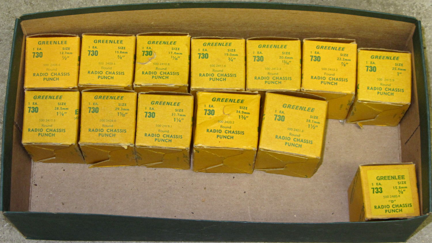
This set of punches is probably worth its weight in, uh, tool steel, because Greenlee got out of the Radio Chassis Punch business quite a while ago:
Greenlee 730 Radio Chassis Punch Assortment
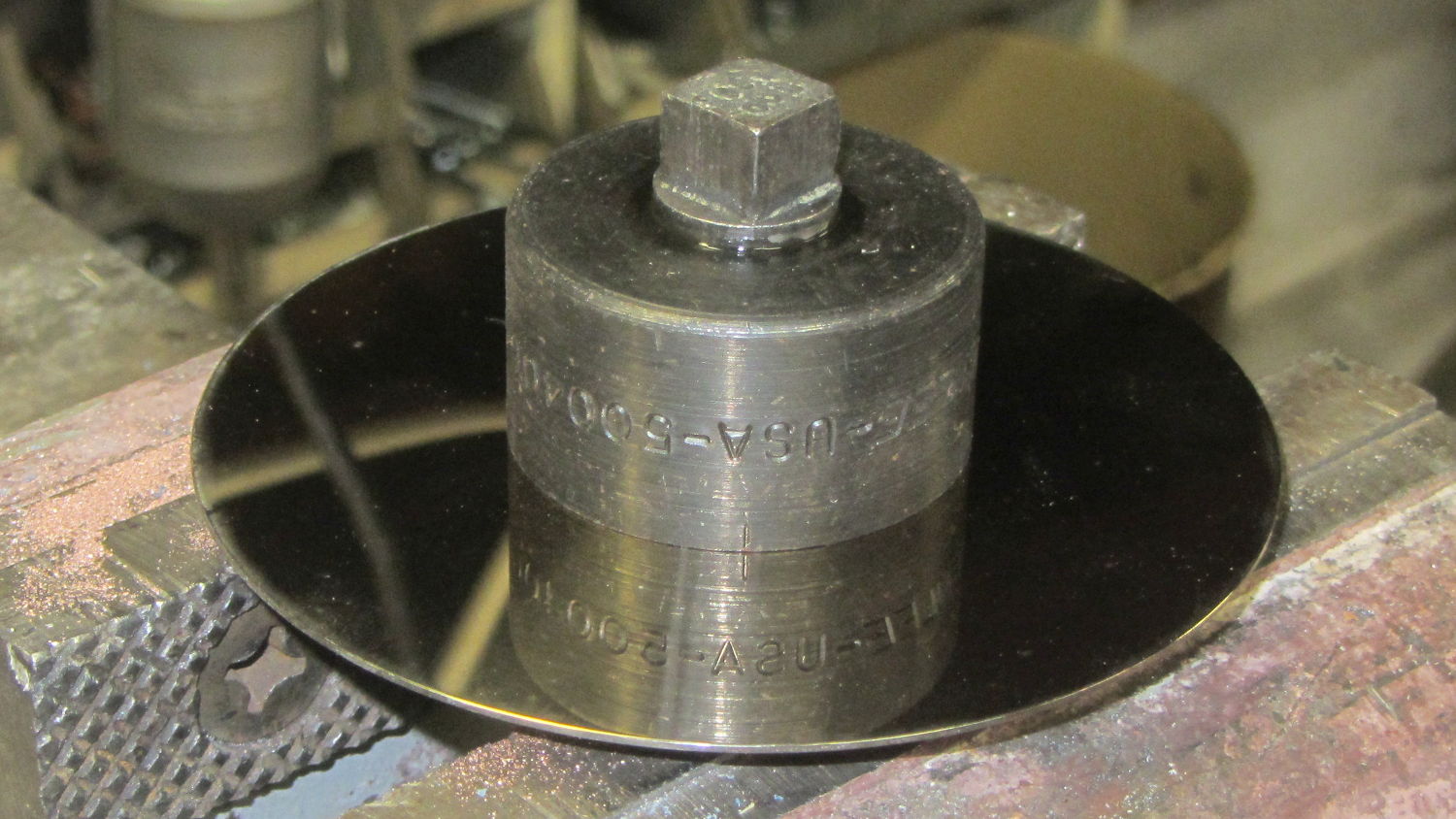
As far as a Greenlee punch is concerned, a hard drive platter looks a lot like thin aluminum sheet:
Greenlee punched drive platter
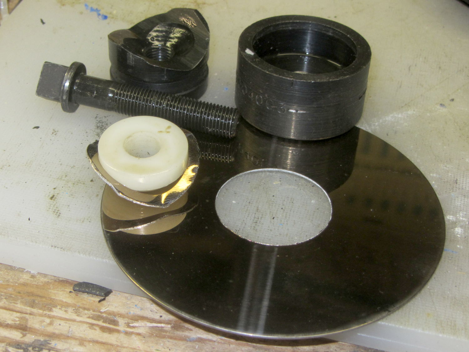
I lathe-turned that white bushing to align the hard drive platter around the screw inside the punch. The right way to make that bushing in this day & age definitely involves 3D printing, but I was standing next to the lathe and spotted a nylon rod in the remnants bucket underneath.
The inner ring crumples around the bushing inside the die, while the platter outside remains flat & undamaged through the entire experience.
I match-marked the socket & “plate cap lead” holes on the punched platter and introduced it to Mr Drill Press, but the right way to do that for more than one socket / plate involves a Sherline mill fixture and some CNC.
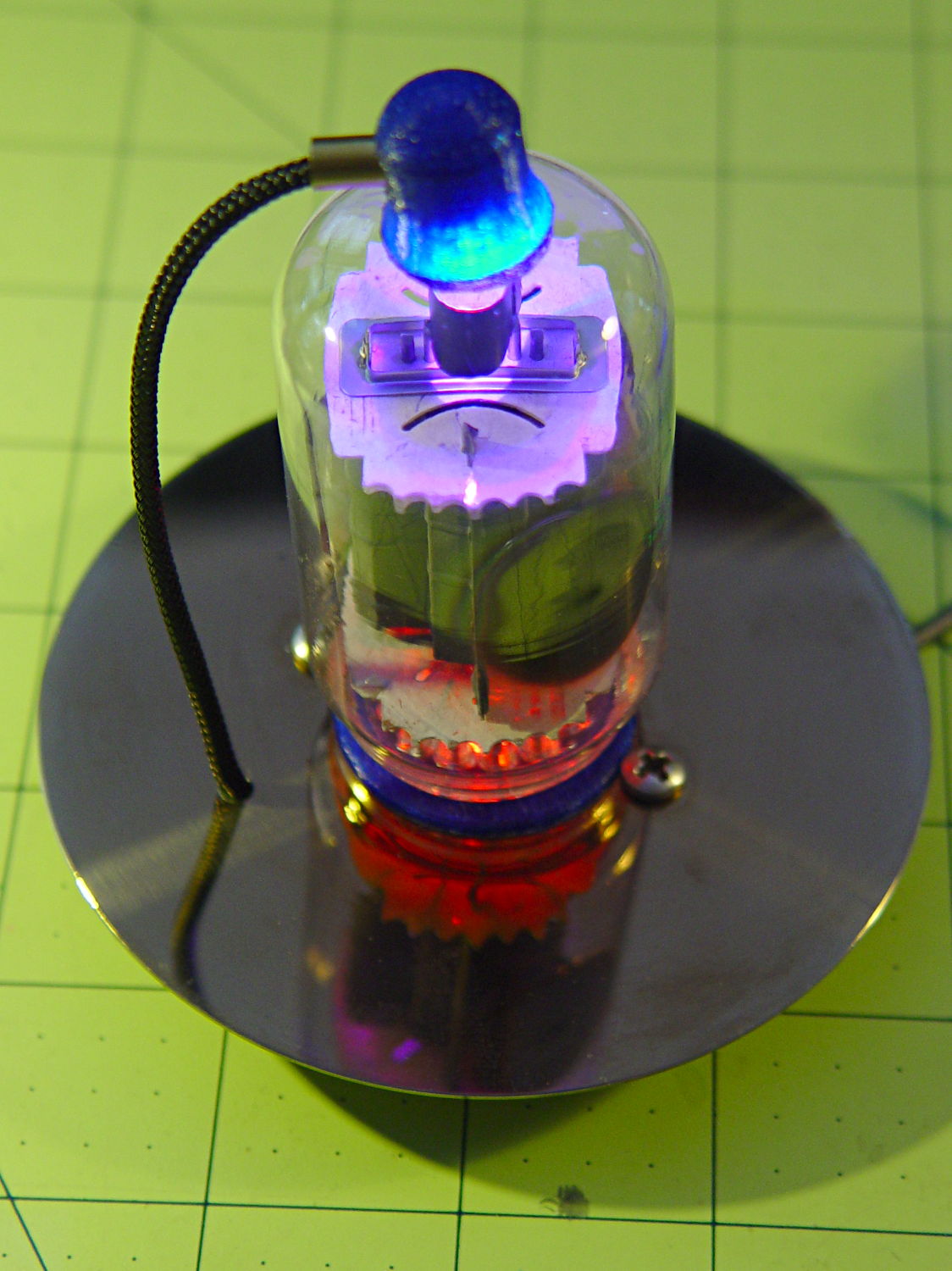
And then It Just Worked:
Vacuum Tube LEDs – IBM 21HB5A drive platter socket
That’s obviously a proof of concept; the socket rests on the desk with the rest of the tubes / sockets / Neopixels tailing off to the right. The plate cap lead should pass through a brass tube fitting on the platter, just for pretty.
The 7- and 9-pin sockets have a raised disk that’s slightly smaller than the 25 mm hard drive hole; the easiest fix involves slightly enlarging the disk to match the hole. Although CDs / DVDs have a 15 mm hole and Greenlee punches work surprisingly well on polycarbonate, if I’m going to CNC-drill the screw / wire holes anyway, CNC milling the middle hole should go quickly and eliminate a messy manual process.
Come to think of it, that big tube would look better in the middle of a DVD amid all those nice diffraction patterns from the RGB LEDs in the cap…
For reasons that should not require explanation by now, Mary just acquired a large sewing table (along with a Sears Kenmore Model 158 sewing machine that’s slightly older and fancier than the three we already have). The table has an opening fitted to the machine base, but the rubber pads atop the leveling screws had long since stiffened up and two screws were frozen in place. A few drops of penetrating oil released the screws and, mirable dictu, they have ordinary 6-32 threads.
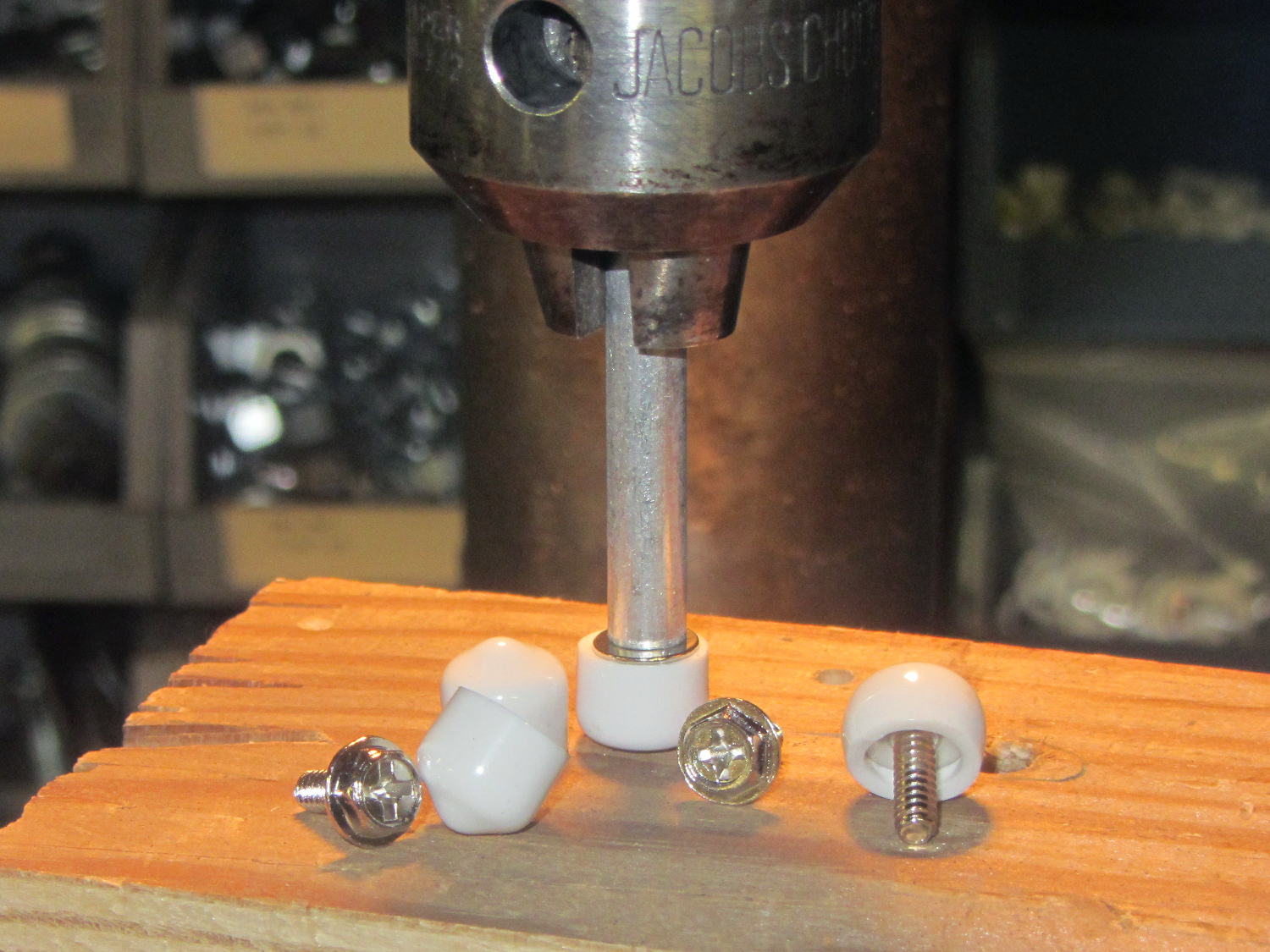
Some rummaging turned up four PC case screws and soft caps intended for wire shelves, which easily combined into replacement machine supports:
Sewing Machine Supports – inserting screws
Once again, I’m using the drill press as a low-force arbor press, with a chunk of aluminum tubing to shove the screw flange into the slightly smaller plastic cap.
Spun into their brackets, they look quite nice, not that anybody will ever see them:
Sewing Machine Supports – installed
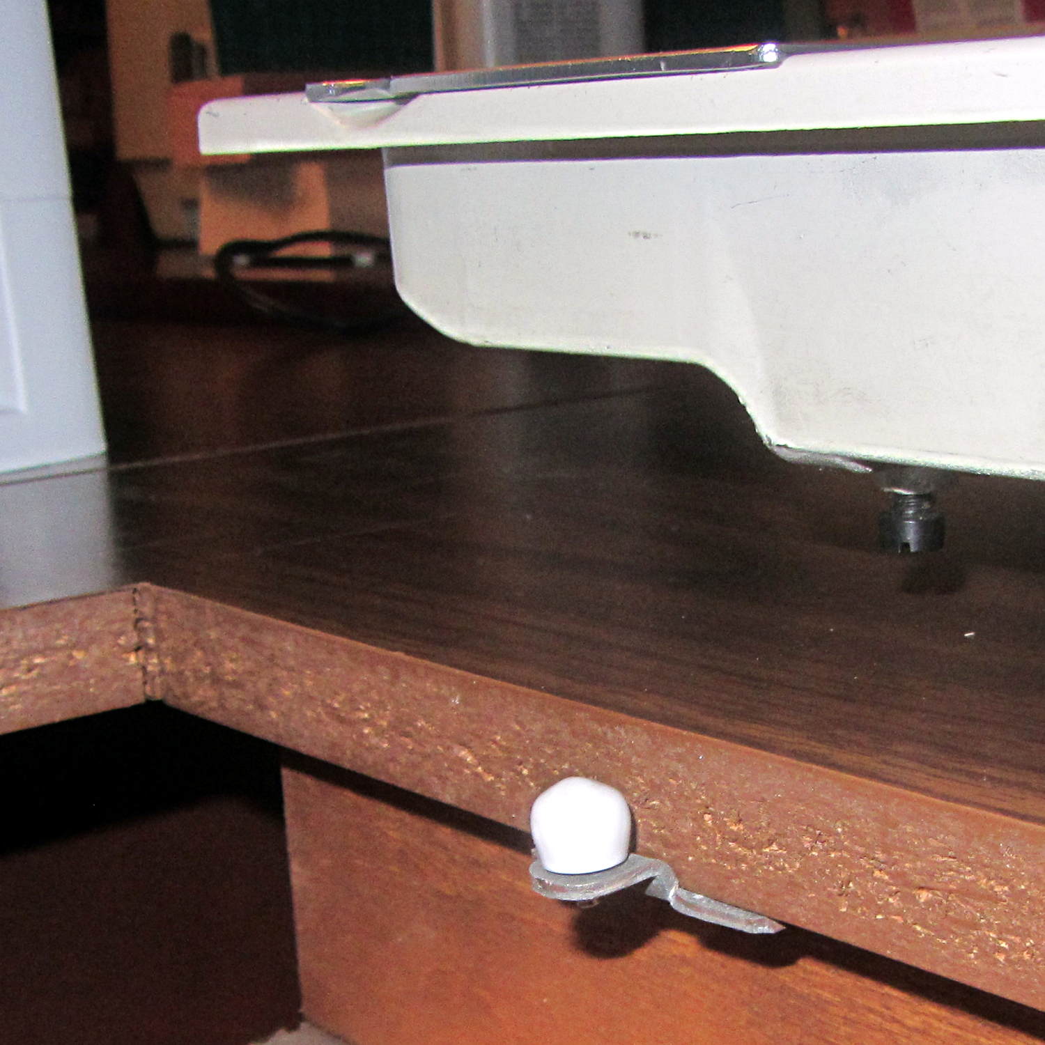
The new-to-us table replaces the incredible collection of junk previously supporting Machine #3. I tucked some plastic foam around the near and right edges to fill the small gaps and it fits well:
Sewing Machine Supports – machine installed
Obviously, the foam will fall out whenever Mary lifts the machine to tinker with machinery under the platform, so we’ll see how often pins & needles slip through the cracks without the foam.
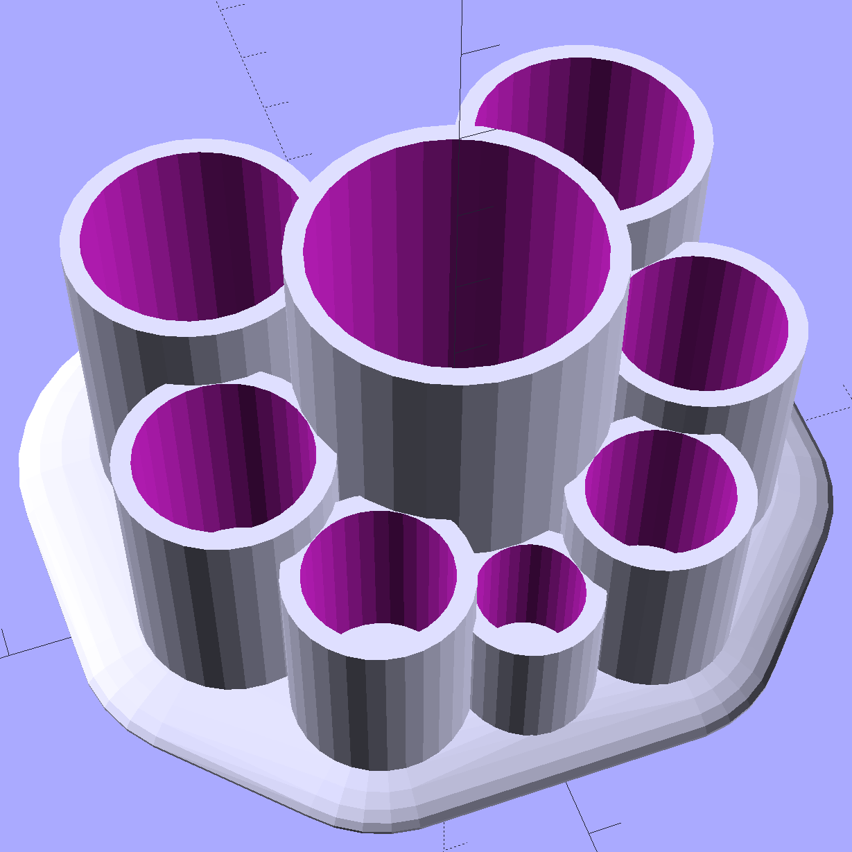
Mary asked for a less angular version of the Lip Balm Holder, which gave me a chance to practice my list comprehension:
Improved Lipstick and Balm Holder
You hand the OpenSCAD program a list of desired tube diameters in the order you want them, the program plunks the first one (ideally, the largest diameter) in the middle, arranges the others around it counterclockwise from left to right, then slips a lilypad under each tube.
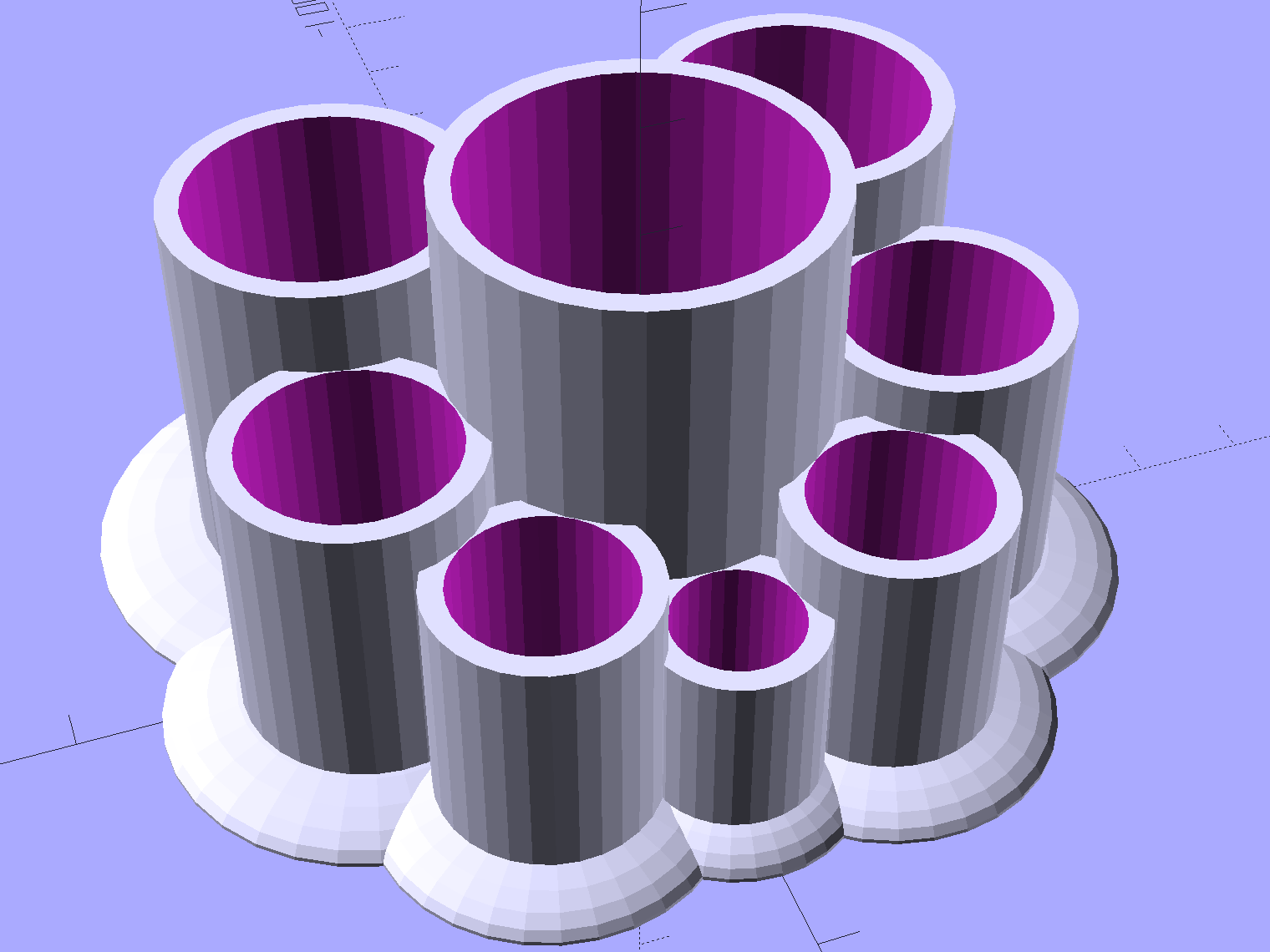
As long as you don’t ask for anything egregiously stupid, the results look reasonably good:
Improved Lipstick and Balm Holder – 8 tubes
As before, each tube length is 1.5 times its diameter; the lipsticks / balms fit loosely and don’t flop around.
Given the tube diameters and the wall thickness, list comprehensions simplify creating lists of the radii from the center tube to each surrounding tube, the center-to-center distances between each of the outer tubes, and the angles between successive tubes:
// per-tube info, first element forced to 0 to make entries match RawDia vector indexes

Radius = [0, for (i=[1:NumTubes-1]) (TubeRad[0] + TubeRad[i] + Wall)];			// Tube[i] distance to center pointRadius = [0, for (i=[1:NumTubes-1]) (TubeRad[0] + TubeRad[i] + Wall)];			// Tube[i] distance to center point
echo(str("Radius: ",Radius));

CtrToCtr = [0, for (i=[1:NumTubes-2]) (TubeRad[i] + TubeRad[i+1] + Wall)];		// Tube[i] distance to Tube[i+1]
echo(str("CtrToCtr: ",CtrToCtr));

Angle = [0, for (i=[1:NumTubes-2]) acos((pow(Radius[i],2) + pow(Radius[i+1],2) - pow(CtrToCtr[i],2)) / (2 * Radius[i] * Radius[i+1]))];
echo(str("Angle: ",Angle));

TotalAngle = sumv(Angle,len(Angle)-1);
echo(str("TotalAngle: ",TotalAngle));
The angles come from the oblique triangle solution when you know all three sides (abc) and want the angle (C) between a and b:
C = arccos( (a2 + b2 - c2) / (2ab) )
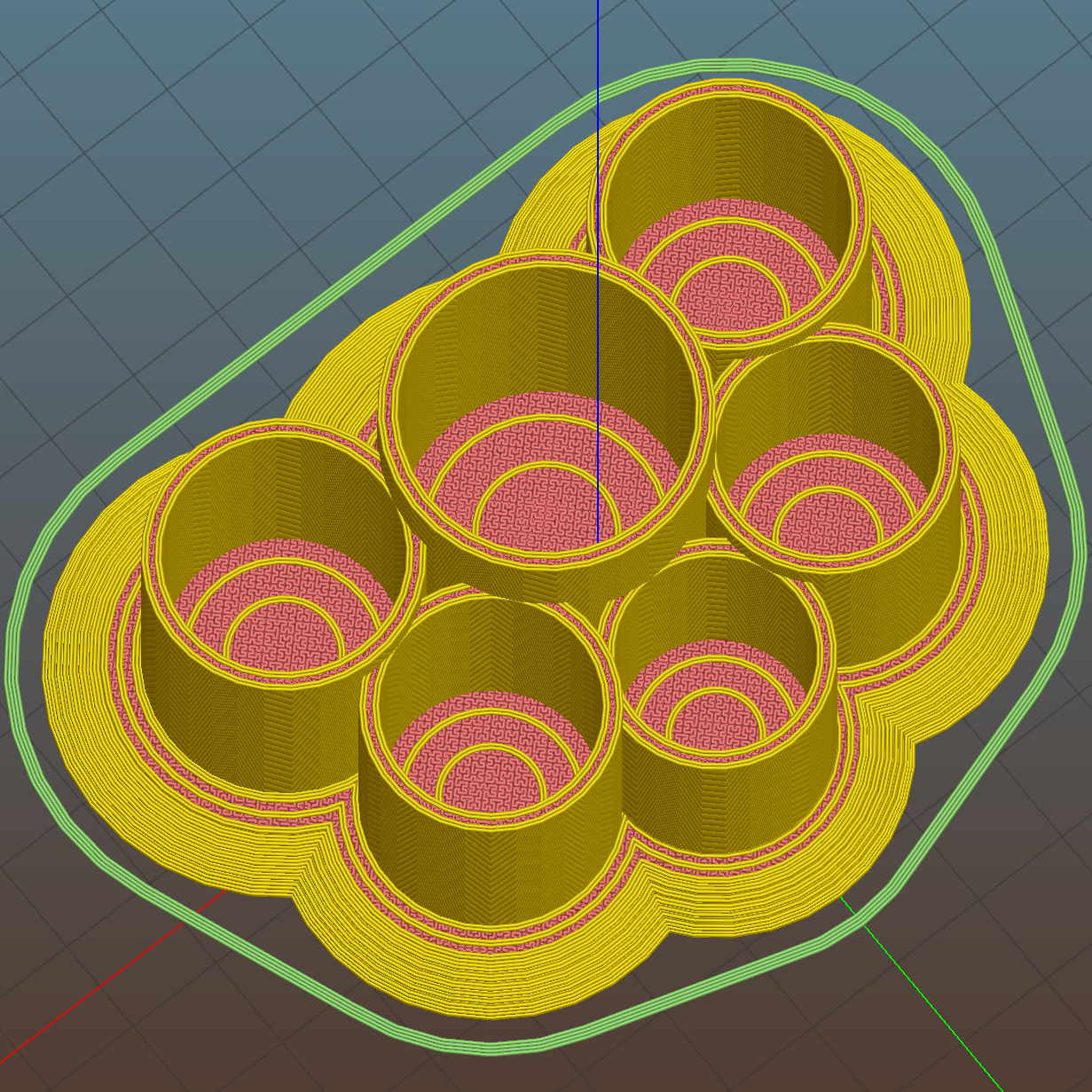
Peering down inside, the Slic3r preview shows the lily pads are the tops of squashed spheres:
Improved Lipstick and Balm Holder – Slic3r preview
The pads are 2.0 times the tube diameter, which seemed most pleasing to the eye. They top out at 2.0 mm thick, which might make the edges too thin for comfort.
I’m awaiting reports from My Spies concerning the typical diameter(s) of lipstick tubes, then I’ll run off a prototype and see about the lily pad edges.
The OpenSCAD source code as a GitHub gist:
This file contains hidden or bidirectional Unicode text that may be interpreted or compiled differently than what appears below. To review, open the file in an editor that reveals hidden Unicode characters.
Learn more about bidirectional Unicode characters
The fourth Sony MicroSDXC card went into service in late September 2015 and has now failed after about 60 sessions in my Sony HDR-AS30 Action Camera. This one sported a U3 speed rating and I had hopes that would improve its longevity, but that doesn’t seem to be true.
The defunct Sony card (marked in red to avoid confusion) will join its defunct compadre and the Sandisk Extreme Pro card goes in the camera:
Sony 64 GB MicroSD SR-64UX – failure
The 16 bike rides in December added up to 220 GB; call it 13.75 GB/trip. January 2016 shows only three rides and it failed after two February rides: barely 60 rides for a total of 825-ish GB of video data. The three previous Sony cards failed after less than 1 TB of data, putting this one in the same ballpark.
I have no way to measure the actual write speed, but the camera shuts down after recording less than a minute of 1920×1080 @ 60 f/s video. Previous cards worked fine at lower video resolutions and recording speeds; I’ll assume this one behaves similarly. It might make a capacious “disk” for a Raspberry Pi.
When the previous card failed, Sony’s “customer support” decided that there might be something wrong with the camera’s firmware causing it to trash the cards, so there was no point in replacing the card under warranty and I should send the camera in for a checkup. When I pointed out that they’d strung me along for a year, until the camera was out of warranty, without mentioning even the possibility that the camera might be at fault and asked whether they’d pick up the $100+ bill for having the camera “examined”, the Nice Man said Level 2 would get back to me after “48 working hours”. When prodded, he agreed that “48 working hours” equaled “6 working days” and didn’t include weekends; when we had that settled, I knew they had no further interest in this matter.
Sony hasn’t called back and, by now, I don’t expect they ever will. It’s not worth my time to pursue this any further, but if you’re wondering how well Sony MicroSD cards work in Sony cameras and how well they support the failures, now you know.
So, starting with this riding season, we’ll see how long a Sandisk Extreme Pro card survives…
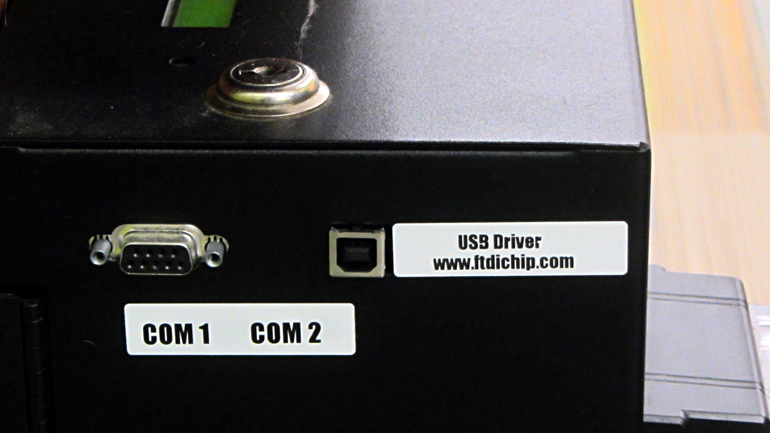
The library kiosk that handles paying your overdue book fines:
Fine payment kiosk with driver info
Now, you’d need to know a few things about what’s going on inside, but I’d say they’re pretty much rolling out the welcome mat for you to find those things out…
Wanna bet it’s running Windows, just like all the electronic voting machines?
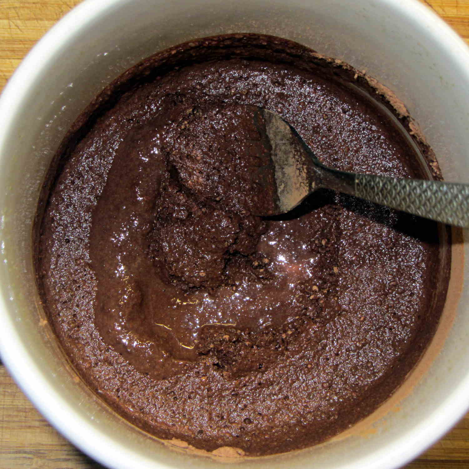
It turns out that non-alkalized / non-Dutch-process cocoa has a much lower surface energy than good old Hershey’s, to the extent that my Fireball Cocoa Recipe produces powder bombs, even after far more stirring than I’m willing to exert.
The trick is to stir the mud for a while, then let it set for 15 minutes:
Cocoa mud
That apparently gives the cocoa time to get along with the milk and join forces. Stir it up again, let it sit for a few minutes, then proceed with the recipe: smooooth cocoa with no powder bombs.
A bit more Vietmamese cinnamon is no bad thing, either …
At least on my network, disabling the IPv6 functions makes Avahi start up faster. You do that by tweaking the obvious IPV6 line in /etc/avahi/avahi-daemon.conf: