The Smell of Molten Projects in the Morning

Ed Nisley's Blog: Shop notes, electronics, firmware, machinery, 3D printing, laser cuttery, and curiosities. Contents: 100% human thinking, 0% AI slop.

Author: Ed

  • Refrigerator Trim Tab: Now With Inserts

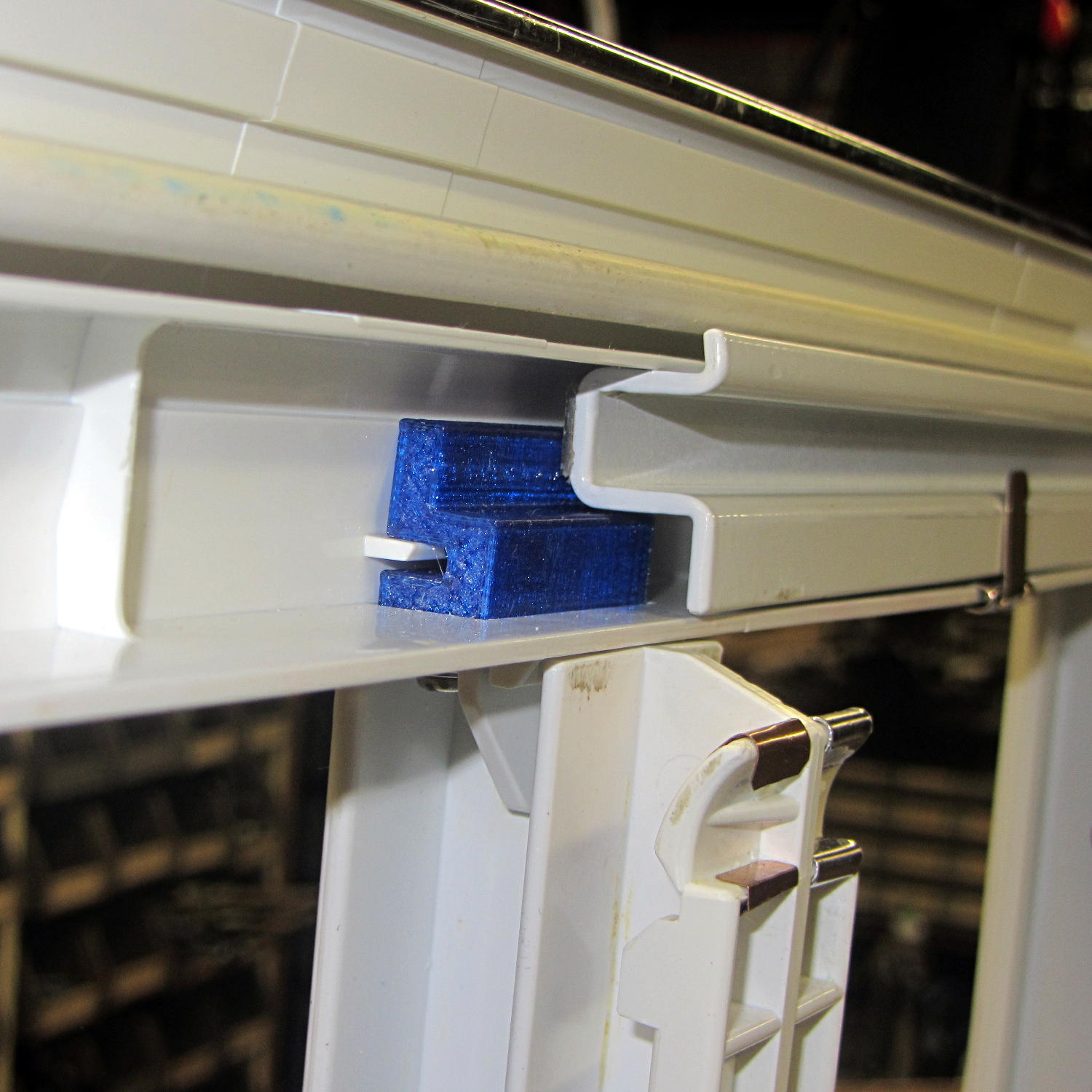
    If the only tool you have is a knurled brass insert, well, then, you use ’em everywhere:

    Refrigerator Trim - melt-installed inserts
    Refrigerator Trim – melt-installed inserts

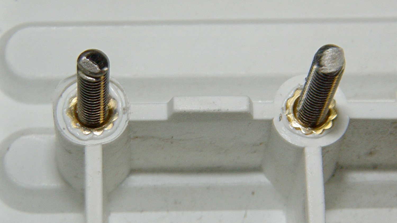
    Those are mounting holes for the little trim tab that closes one of the two holes left for the door hinge bracket on the vent grill of our refrigerator. The tab originally had a pair of the flimsiest little plastic pegs you’ve ever seen, both of which broke off and got themselves repaired with epoxy at least once along the way.

    The holes in the bosses started out only slightly larger than the 4-40 insert body diameter, so they were surely undersized, and the knurls definitely stretched the plastic on the way in. I applied a soldering iron to the studs until the plastic melted around the knurls, relieved much of the stretching, and secured those puppies forevermore.

    I was willing to try heat-setting them because I absolutely didn’t care if they came out a little crosseyed. For future reference, the inserts will cant off-axis unless they’re held in place: use a drill press or something similar as an alignment fixture. That would be awkward with three feet of grill hanging off the drill press table.

    I step-drilled (to avoid grabbing the soft plastic) the tab with slightly oversized 1/8 inch holes to allow some adjustment for best fit. A trial assembly showed a pair of greatly oversized 6-32 nylon standoffs spaced it well enough from the bosses for my simple needs:

    Refrigerator Trim - trial fit
    Refrigerator Trim – trial fit

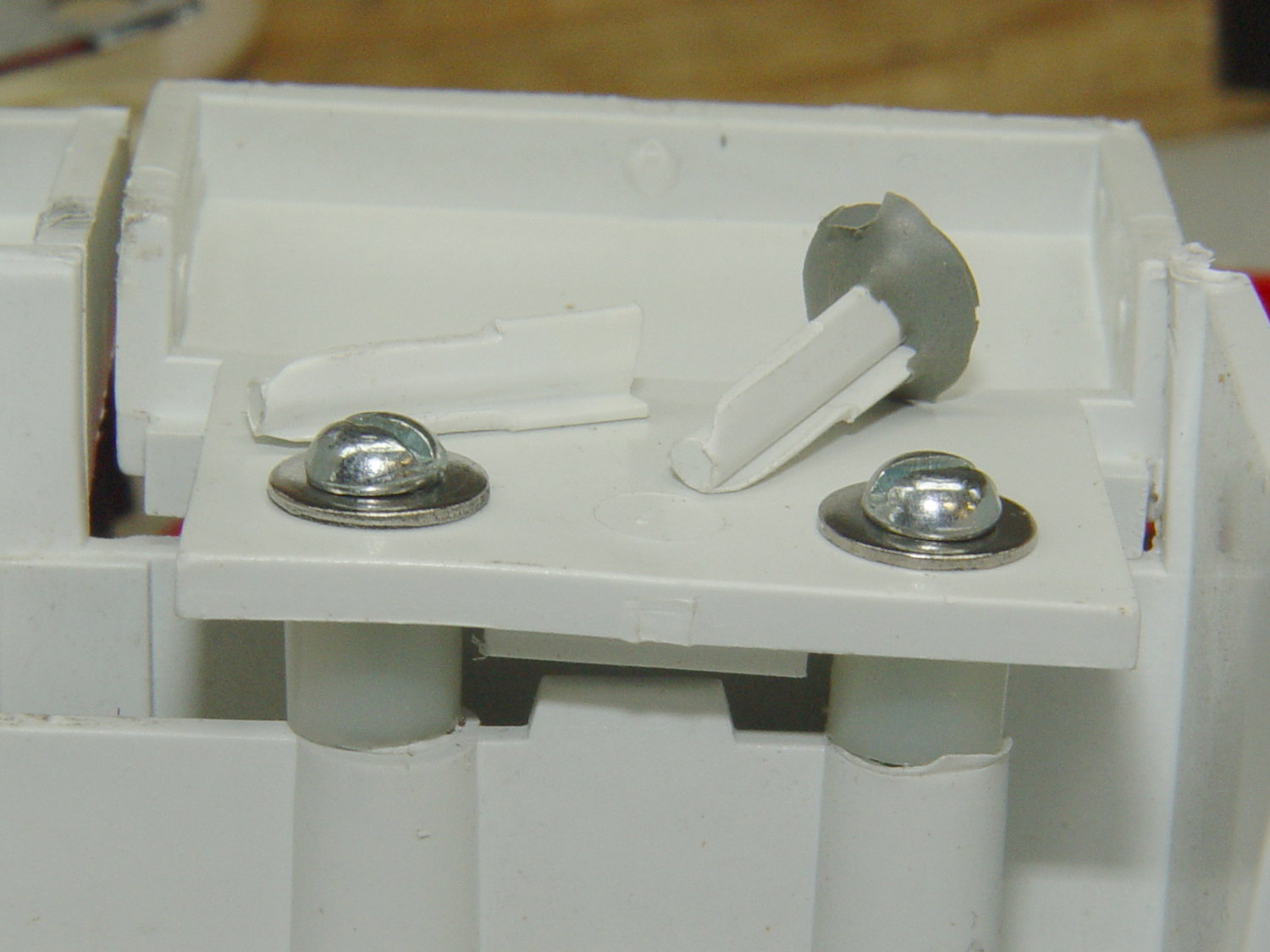
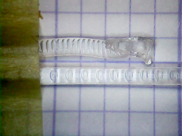
    The two broken pegs sit disconsolately atop the tab, with the crushed section of their ribs showing their depth of insertion in the bosses. Note that the tab sits proud of the grill, originally supported entirely by the pegs and stopped by the square block in the middle, with no support or alignment on any side.

    The left peg popped out of its epoxy blob, forcing me to file the blob flat before drilling through both it and the tab.

    After some wiggle-n-jiggle adjustment, the tab lined up a bit better, I defined it to be Good Enough, and popped the grill back in place on the refrigerator.

    Done!

  • It’s Right on Red After Stopping

    I’m returning home after accompanying Mary to her morning of volunteering in the Locust Grove veggie gardens. The Locust Grove gate faces predominantly left-turning traffic from Beechwood Avenue, so I’ll be watching the vehicles approaching head-on.

    T = 0.000 – Signal turns green:

    Rt 9 Locust Grove - Right on Red - front camera - 0135
    Rt 9 Locust Grove – Right on Red – front camera – 0135

    T = 2.500 – Entering the intersection:

    Rt 9 Locust Grove - Right on Red - front camera - 0270
    Rt 9 Locust Grove – Right on Red – front camera – 0270

    I don’t start pedaling until the signal in my direction actually turns green, because drivers have been known to blow through intersections with a fresh red signal. Two seconds seems like a reasonable delay.

    T = 5.500 – Three lanes later, nearing the midline of Rt 9 and still accelerating:

    Rt 9 Locust Grove - Right on Red - front camera - 0465
    Rt 9 Locust Grove – Right on Red – front camera – 0465

    T = 5.917 – The black car in the right lane is moving and I begin to look that way:

    Rt 9 Locust Grove - Right on Red - front camera - 0490
    Rt 9 Locust Grove – Right on Red – front camera – 0490

    I cannot tell from the video whether the driver actually stopped (as you’re required to do for “right on red after stop“, but nobody actually does) or just slowed into a rolling stop for the turn.

    Why not slam to a stop in the middle of Rt 9 in front of the left-turning traffic? Come for a ride with me and we’ll try that out. I’ll shout “LOOK OUT!” at some inopportune time when you’re in the middle of traffic and not expecting it, whereupon you must hit the brakes and deal with the consequences.

    T = 7.117 – One second later, I’m beginning to veer left, directly toward the stream of oncoming traffic turning toward me:

    Rt 9 Locust Grove - Right on Red - front camera - 0562
    Rt 9 Locust Grove – Right on Red – front camera – 0562

    In round numbers, the black car moved 35 feet in 1.2 s between those frames: 30 feet/s = 20 mph.

    T = 7.750 – The white car on my right continues turning and I’ll definitely clear its rear:

    Rt 9 Locust Grove - Right on Red - front camera - 0600
    Rt 9 Locust Grove – Right on Red – front camera – 0600

    The black car has moved another 15 feet in 633 ms: 24 feet/s = 16 mph.

    I’m wearing the vest part of my fluorescent green jacket over a fluorescent green shirt with fluorescent green gloves. By now, I think I’ve been sighted, at ten feet and closing.

    T = 8.383 – The only clear area lies directly ahead of the oncoming silver car:

    Rt 9 Locust Grove - Right on Red - front camera - 0638
    Rt 9 Locust Grove – Right on Red – front camera – 0638

    T = 9.000 – I’m approaching the yellow line, probably won’t sideswipe the silver car, and the black car is now braking:

    Rt 9 Locust Grove - Right on Red - front camera - 0675
    Rt 9 Locust Grove – Right on Red – front camera – 0675

    T = 9.583 – The black car has nearly stopped:

    Rt 9 Locust Grove - Right on Red - front camera - 0710
    Rt 9 Locust Grove – Right on Red – front camera – 0710

    The wide-angle lens on the HDR-AS30V makes it look like I had plenty of room. The Fly6 rear camera shows why I had reason for concern:

    Rt 9 Locust Grove - Right on Red - rear camera - 0323
    Rt 9 Locust Grove – Right on Red – rear camera – 0323

    I’m still moving, the black car is slowing:

    Rt 9 Locust Grove - Right on Red - rear camera - 0332
    Rt 9 Locust Grove – Right on Red – rear camera – 0332

    T = 9.767 – Props to this driver for not starting quickly:

    Rt 9 Locust Grove - Right on Red - front camera - 0781
    Rt 9 Locust Grove – Right on Red – front camera – 0781

    Elapsed time: four seconds from spotting the black car not stopping in the right-turn lane.

    I moved back to the right side of the lane and continued the mission, but decided I didn’t need a jaunt across town to the rail trail before the rain set in to get my heart rate up.

  • Refrigerator Drawer Strut Tab: Now With Inserts

    A spate of cleaning put the little tab that fixed the never-sufficiently-to-be-damned strut supporting the lower refrigerator drawers into my hands:

    Refrigerator Drawer Strut - new tab in place
    Refrigerator Drawer Strut – new tab in place

    I discovered that 4-40 knurled inserts perfectly match the available space, so I drilled the 3D printed holes out to 11/16 inch (the OD of the smaller knurls) and rammed the inserts into place:

    Refrigerator Drawer Strut Tab - knurled inserts
    Refrigerator Drawer Strut Tab – knurled inserts

    No epoxy, no heat, nothing but a friction fit.

    Looks much better, ought to work just as well, and will definitely outlive the refrigerator; if I never take that thing apart again, it’ll be fine with me.

  • Filament Drive Gear Calculations

    Some equations relevant to indentations produced by a filament drive gear:

    Filament Drive Gear Indentations
    Filament Drive Gear Indentations

    For reference, the smaller indentations are 0.25 mm deep and 1.3 mm across the bottom.

    Variables:

    • d = filament (a.k.a. circle) diameter
    • r = filament radius
    • m = chord depth (inward from circle)
    • c = chord length
    • Θ = angle across chord from circle center, degrees
    • A = chord area (a.k.a. indentation face area)

    The length of the chord at the bottom of the indentation, perpendicular to the filament axis:

    c = 2 sqrt(2mr - m2)

    The chord angle:

    Θ = 2 arcsin(c/2r)

    The chord area, which would be the indentation face if it were perpendicular, which it isn’t:

    A = (r2 / 2) x ((πΘ / 180) - sin(Θ))

    If you measured Θ in radians, the π/180 factor would Go Away.

    Some doodles showing that reducing the indentation from 0.25 to 0.15 reduces the chord area by a factor of two:

    Filament Drive Gear - indentation doodles
    Filament Drive Gear – indentation doodles

    The implication being that you must maintain fairly constant force on the drive bearing against the filament to prevent stripping the indentations.

  • M2 Platform Alignment Check

    Five single-thread thinwall boxes scattered across the platform had an average height of  2.99 mm, with a range of +0.04 mm, -0.06 mm:

    Thinwall open box - 1 thread walls
    Thinwall open box – 1 thread walls

    The wall widths work out to 0.39 mm, with a range of +0.2 mm, -0.01 mm.

    Close enough, given that I can’t recall the last time I tweaked the platform height. I update the filament diameter setting in Slic3r every now & again as the printer gradually works through the spool, but, with one exception, this cyan PETG has been quite consistent and my tweaks didn’t really amount to much.

    Frankly, given that any of the measurements may be off by ±0.02, the best I can hope for is an overall warm fuzzy feeling. When the printed results stop looking good, these results will (probably) provide some indication of whatever just changed.

    The raw measurement data, such as it is:

    Thinwall box measurements - 2016-04-01
    Thinwall box measurements – 2016-04-01
  • Thinwall and Solid Boxes for 3D Printer Calibration

    A revision to my Fundamental Calibration Object adds some variations …

    The classic thinwall open box:

    Calibration Box - open - 1 thread - solid model
    Calibration Box – open – 1 thread – solid model

    A solid box:

    Calibration Box - solid - solid model
    Calibration Box – solid – solid model

    A solid box with text embossed on the lower surface:

    Calibration Box - solid text - solid model
    Calibration Box – solid text – solid model

    You must consider how the slicer settings interact with the solid model parameters, particularly now that slicers can produce adaptive infill for small gaps between perimeter threads. Previewing the slicer’s output will show you what assumptions it makes and prevent surprising results out there on the platform.

    A single-thread wall comes out properly:

    Thinwall open box - 0.40 wall - Slic3r
    Thinwall open box – 0.40 wall – Slic3r

    The results look just like the preview, with firmly bonded layers and no fluff:

    Thinwall open box - 1 thread walls
    Thinwall open box – 1 thread walls

    This wall should be two threads wide, but Slic3r inserts very very thin infill thread:

    Thinwall open box - 0.80 wall - Slic3r
    Thinwall open box – 0.80 wall – Slic3r

    I think that’s a result of forcing the two perimeter threads to sit with their centers exactly one thread width apart, making the (nominal, ideal) inner walls tangent to each other.  Setting the wall to 1.9 mm eliminates the hair-fine infill thread, at the cost of producing an object 0.1 mm smaller than it looks.

    Unfortunately, that fine infill doesn’t produce enough plastic flow for a continuous thread. The PET I’m using accumulates on the nozzle until enough of a glob forms to stick on the previous layer, but hair-fine strands connect those globs to each other and the nozzle, producing awful results:

    Thinwall open box - 2 thread walls
    Thinwall open box – 2 thread walls

    A triple-thread wall allows Slic3r to produce a fatter infill thread that works the way you’d expect:

    Thinwall open box - 1.20 wall - Slic3r
    Thinwall open box – 1.20 wall – Slic3r

    The threads bond firmly in all directions:

    Thinwall open box - 3 thread walls
    Thinwall open box – 3 thread walls

    It’s not obvious from that picture, but the bond between successive infill threads produces a glass-clear vertical plastic slab that relays images from the bottom to the top. The perimeter threads are also firmly bonded, albeit with not quite the same optical quality.

    To use these boxes:

    • Set the OpenSCAD extrusion parameters to match whatever the slicer will use
    • Set the wall height and thickness to whatever you like
    • Compile-and-render, export the result as a solid model in STL / AMF / whatever
    • Feed the solid model into your favorite slicer and save the G-Code
    • Feed the G-Code into your printer, watch it magically create a little box
    • Measure the printed results and compare with the ideal settings
    • Change the slicing configuration and iterate until satisfied

    Verify these measurements before adjusting anything else:

    • Filament diameter: actual vs. nominal will be different
    • Extruder steps per millimeter: mark 100 mm on filament, extrude 100 mm, compare

    Then you can verify / adjust some finicky settings:

    • Extrusion multiplier: does the actual single wall width match slicer’s nominal value?
    • Infill density: 100% infill should perfectly fill the solid box
    • Initial Z offset: does actual height match the model setting?
    • Platform alignment: print five boxes at platform center + corners, verify heights
    • First layer adhesion: if these don’t stick, the platform has weak adhesion
    • Minimum time per layer: if the walls slump, you’re printing too fast
    • Extrusion temperature: good bonding and no delamination along any axis

    The OpenSCAD source code as a GitHub gist:

    // Simple calibration boxes
    // Thin wall open box – verify Extrusion Multiplier
    // Solid box – verify infill settings
    // Ed Nisley – KE4ZNU
    // https://softsolder.com/
    Layout = "Open"; // Open Solid
    Texting = "Text!"; // text message on solid box or empty string to suppress
    //——-
    //- Extrusion parameters must match reality!
    ThreadThick = 0.25;
    ThreadWidth = 0.40;
    Protrusion = 0.1; // make holes end cleanly
    function IntegerMultiple(Size,Unit) = Unit * ceil(Size / Unit);
    //——-
    // Dimensions
    WallThick = 1.0 * ThreadWidth;
    echo(str("Wall thickness: ",WallThick));
    BoxSize = 20.0;
    echo(str("Overall size: ",BoxSize));
    NominalHeight = 3.0;
    echo(str("Nominal height: ",NominalHeight));
    Height = IntegerMultiple(NominalHeight,ThreadThick);
    echo(str("Actual height: ",Height));
    Rotation = 0; // 45 to exercise X and Y axis motors at same time
    CornerRadius = 2.0;
    CornerSides = 8*4;
    //——–
    module Solid() {
    difference() {
    hull()
    for (i=[-1,1], j=[-1,1])
    translate([i*(BoxSize – 2*CornerRadius)/2,j*(BoxSize – 2*CornerRadius)/2,0])
    cylinder(r=CornerRadius,h=Height,$fn=CornerSides);
    if (len(Texting))
    translate([0,0,-Protrusion/2])
    linear_extrude(height=3*ThreadThick + Protrusion)
    mirror([1,0,0])
    text(text=Texting,size=6,spacing=1.05,font="ITC Zapf Chancery:style=Italic",halign="center",valign="center");
    }
    }
    module Thinwall() {
    difference() {
    Solid();
    hull()
    for (i=[-1,1], j=[-1,1])
    translate([i*(BoxSize – 2*CornerRadius)/2,j*(BoxSize – 2*CornerRadius)/2,-Protrusion])
    cylinder(r=(CornerRadius – WallThick),h=(Height + 2*Protrusion),$fn=CornerSides);
    }
    }
    //——-
    rotate(Rotation)
    if (Layout == "Open")
    Thinwall();
    else
    Solid();
  • Road Conditions: 2816 Rt 376 Northbound Sinkhole

    We must dodge this sinkhole on every northbound ride, which means about four times a week:

    Rt 376 2016-01-15 - Northbound milepost 1110 - sinkhole
    Rt 376 2016-01-15 – Northbound milepost 1110 – sinkhole

    It’s been sinking, month by month, ever since I reported it to NYSDOT last July. They dispatched a work crew that did a remarkable job of patching everything around the sinkhole (note the asphalt obliterating the center line), but somehow missed the actual hole on the shoulder, despite the picture I sent. Just before snow season, a second crew patched many small holes along Rt 376 from Red Oaks Mill to Hooker Avenue, but, once again, missed this one.

    If it doesn’t look like much, let’s go for a check ride.

    This section of Rt 376 forms part of NYS Bike Route 9.