Ed Nisley's Blog: Shop notes, electronics, firmware, machinery, 3D printing, laser cuttery, and curiosities. Contents: 100% human thinking, 0% AI slop.
Mary used a garbage can lid to shelter some plants, left it in the garden for a while, and a critter moved into the new shelter. She first noticed two well-prepared front entrances:
Garden shelter – front entrances
And a rear entrance or, perhaps, the emergency exit:
Garden shelter – rear entrance
Gingerly lifting the lid, she found a dismantled bird corpse:
Garden shelter – bird corpse
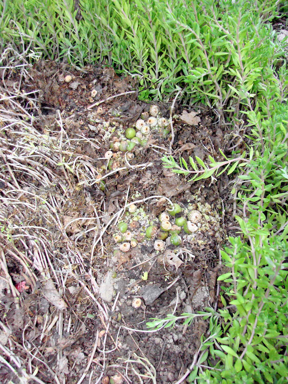
Along with a large stash of sour cherries from a nearby bush:
Garden shelter – sour cherry stash
A good-size toad kept an eye on the proceedings:
Garden shelter – toad in lair
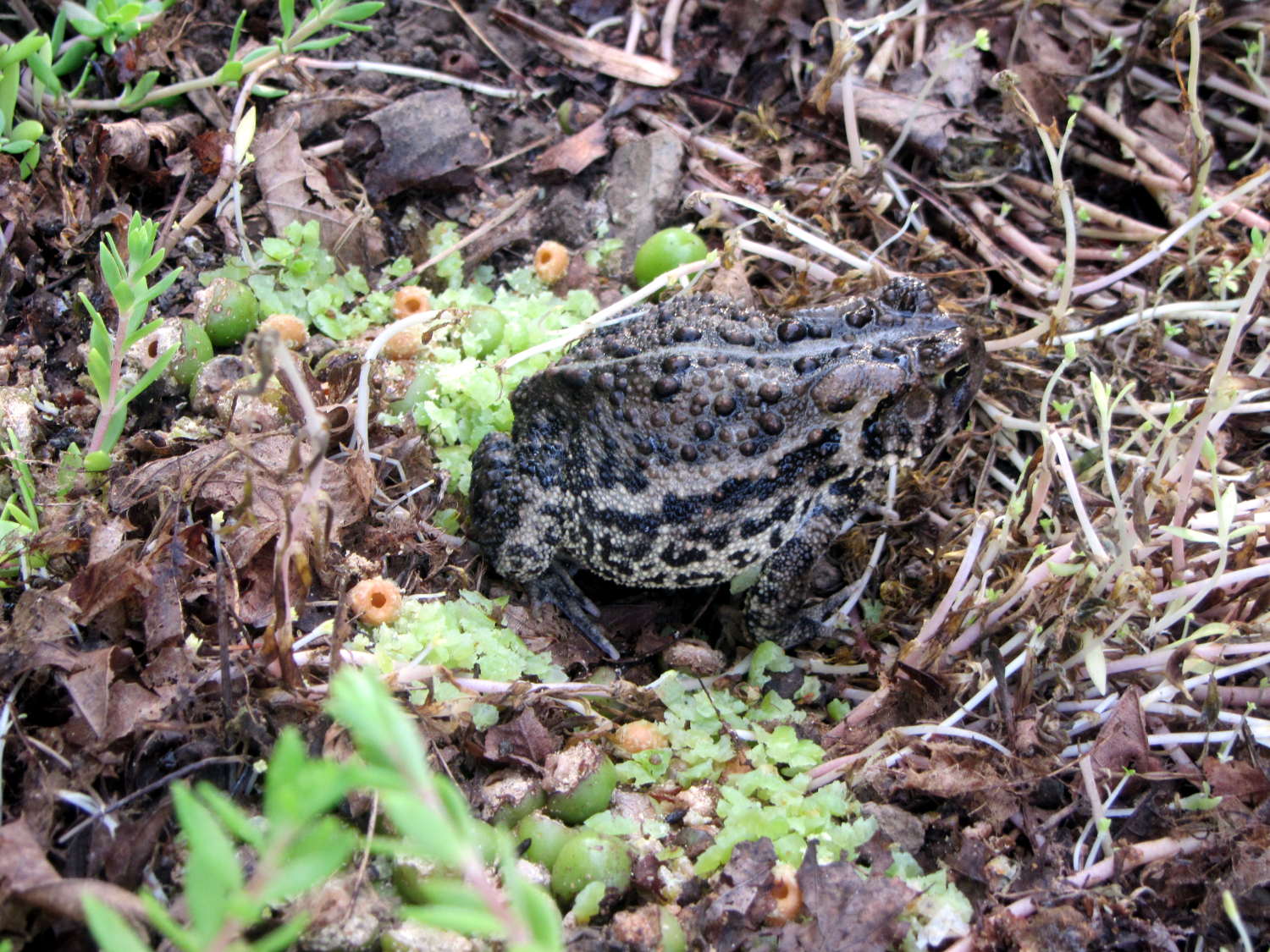
We didn’t know toads ate sour cherries, but the evidence seems clear:
Garden shelter – toad on sour cherries
The image of a toad taking down a bird can’t be unseen, but, more likely, a recently fledged nestling took shelter and couldn’t figure out how to get out again.
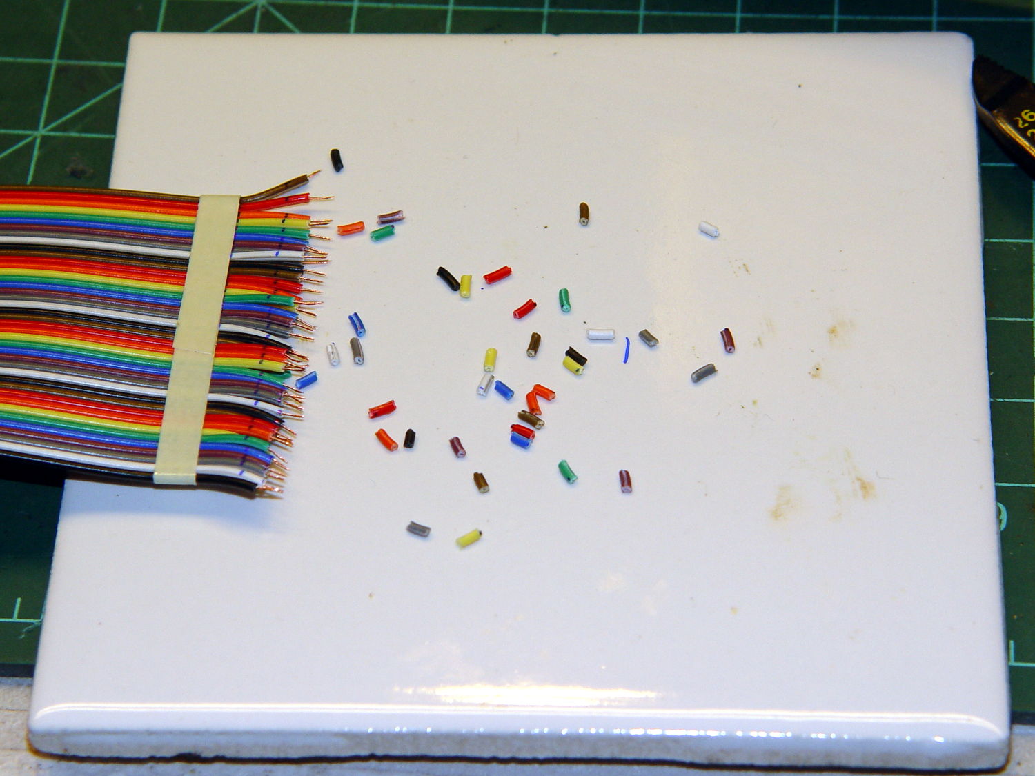
Given five meters of 40 conductor ribbon cable, the object is to make a 40 turn five foot diameter loop antenna by soldering the ends together with a slight offset. After squaring off, marking, and taping the cable ends, I stripped the wires:
LF Loop Antenna – wire stripping
Twirling those little snippets before pulling them off produced nicely twisted wire ends with no few loose strands. Separate the individual wires, wrap with transformer tape to prevent further separation, run a flux pen along the wire ends, tin with solder, repeat on the far end of the cable.
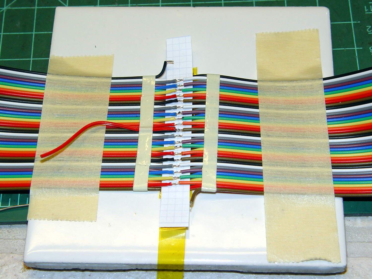
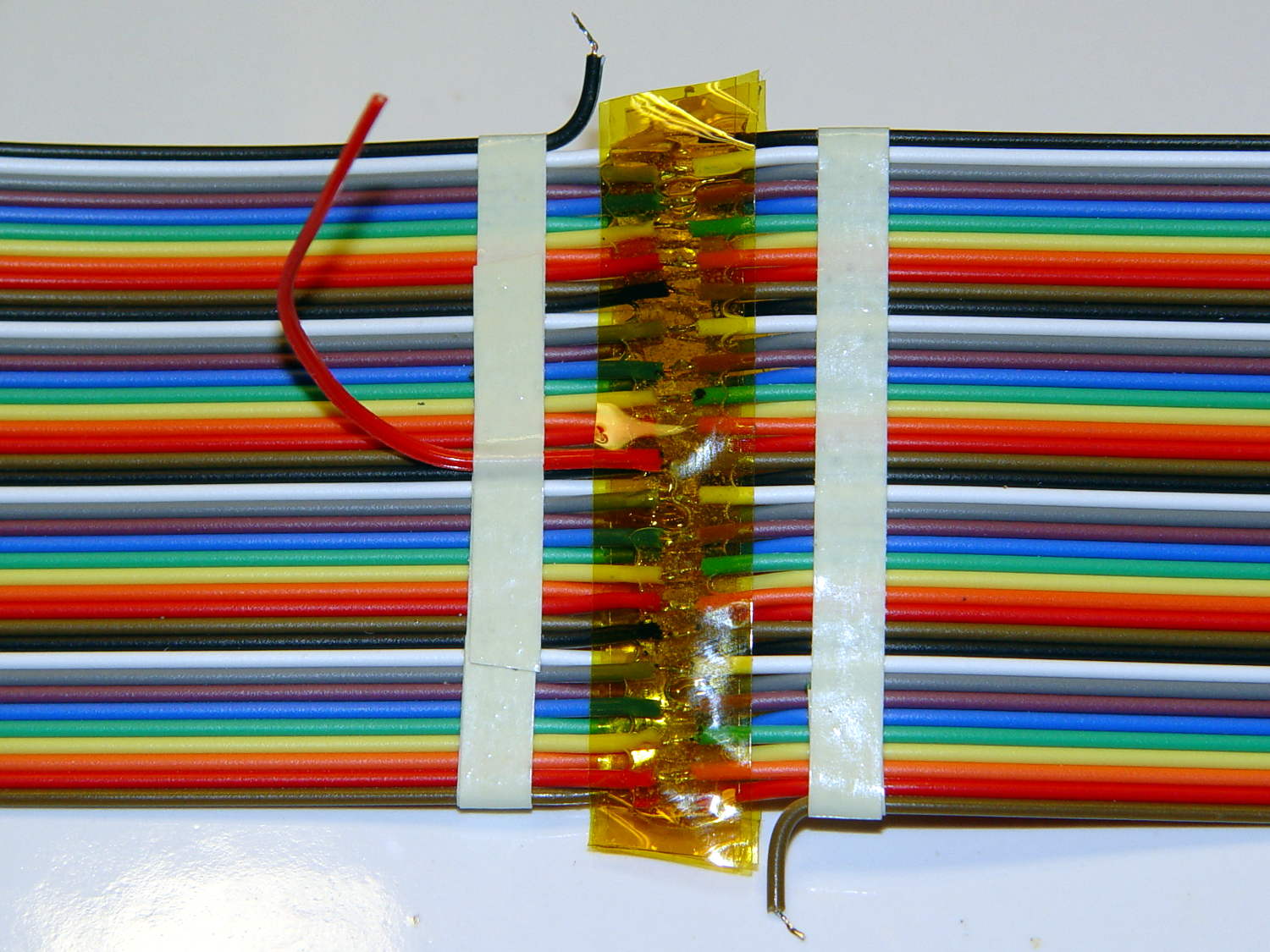
Tape one end to the ceramic tile. Align the other end with a one-wire lateral offset and the stripped sections overlapping, then tape it down. Slide a paper strip between the ends, passing under every other wire, to separate the top pairs from the bottom pairs, then tape the strip in place:
LF Loop Antenna – wire prep
Grab each left wire with a needle point tweezer, forcibly align with the corresponding right wire, touch with the iron, iterate:
LF Loop Antenna – top solder joints
The red wire trailing off to the left will become the center tap.
Slide a strip of the obligatory Kapton tape underneath the finished joints, slobber on enough clear epoxy to bond the insulation on both sides of the joints into a solid mass, squish another strip atop the epoxy, smooth down, wait for curing.
Untape from the tile, flip, re-tape, solder the bottom joints similarly, add Kapton / epoxy / Kapton, and that’s that:
LF Loop Antenna – complete joint
Prudence dictates checking for end-to-end continuity after you finish soldering and before you do the Kapton + epoxy thing, which is where I discovered I had 80 Ω of distributed resistance along 200 meters of cable. A quick check showed 40 Ω at the center tap and 20 Ω at the quarters (the black wires on the left mark those points), so it wasn’t a really crappy joint somewhere in the middle.
The joint and its dangly wires cry out for a 3D printed stiffener which shall remain on the to-do list until I see how the loop tunes up.
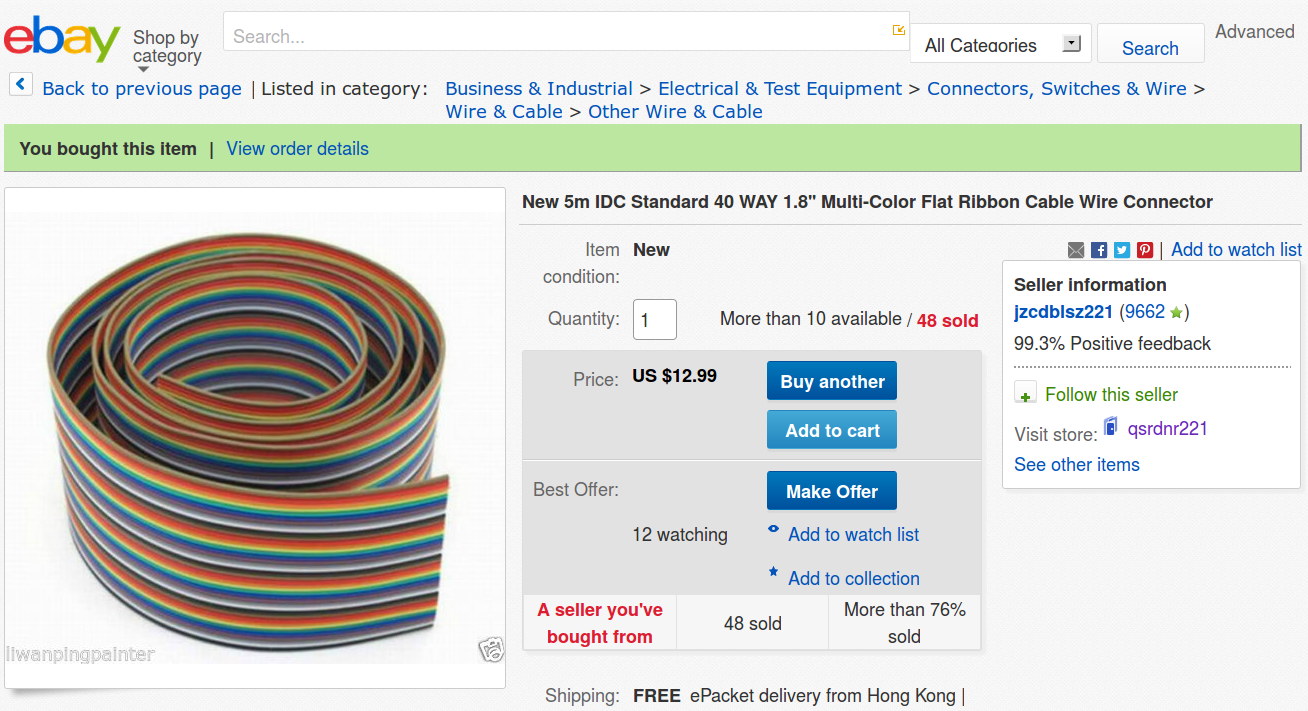
What’s wrong with this picture? (clicky for more dots)
eBay – 40 pin IDC cable – header
Not obvious?
Here’s the description, slightly reformatted for clarity:
New 5m IDC Standard 40 WAY 1.8” Multi-Color Flat Ribbon Cable Wire Connector
Description
Type: IDC standard.
10 colors, 4 group, total 40 pcs cables per lot
5 meter per lot.
width: 4.7 cm / 1.8 inch
Package content: 5M Flat Color Ribbon Cable
If you divide the 1.8 inch cable width by its 40 conductors, you find the wires lie on a 45 mil pitch. If you were expecting this “IDC standard” cable to fit in standard insulation displacement cable connectors with a 50 mil pitch, you’d be sorely disappointed. You can get metric ribbon cable with a 1 mm = 39 mil pitch, but this ain’t that, either.
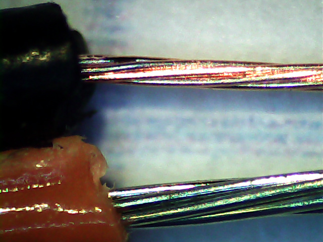
Here’s what an individual eBay wire (black jacket) looks like, compared to a wire from a standard ribbon cable (red jacket):
Ribbon cable – 26 AWG – eBay vs standard
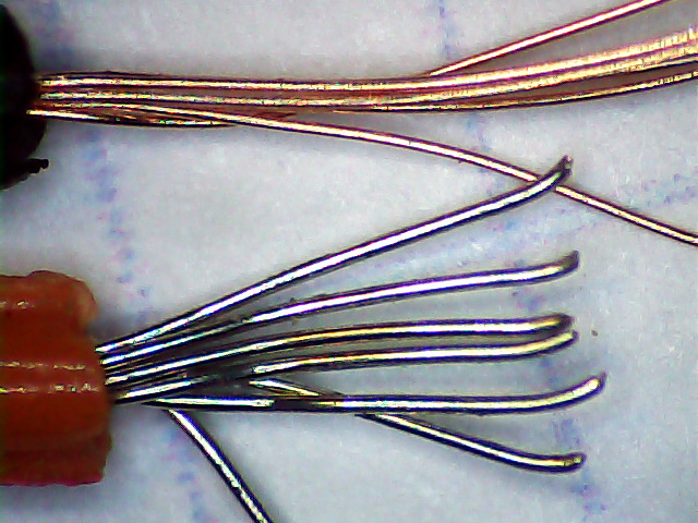
A closer look at the strands making up the wires:
Ribbon cable – 26 AWG – eBay vs standard – strands
As nearly as I can measure with my trusty caliper, the eBay ribbon cable has wire slightly smaller than 30 AWG, made up of seven 40 AWG strands, as opposed to standard 26 AWG wire made of seven 34 AWG strands. The good stuff might be 28 AWG / 7×36 AWG, but I was unwilling to break out the micrometer for more resolution.
I’d like to say I noticed that before buying the cable, but it came to light when I measured the total resistance of the whole cable: 80 Ω seemed rather high for 200 meters of 26 AWG wire. The wire tables say that’s about right for 31 AWG copper, though.
Changing the AWG number by three changes the conductor area by a factor of two, so you’re getting less than half the copper you expected. Bonus: it won’t fit any IDC connectors you have on the shelf, either.
Turns out a recent QEX article suggested building an LF loop antenna from a ribbon cable, so I was soldering all the conductors in series, rather than using connectors, and it should work reasonably well despite its higher DC resistance.
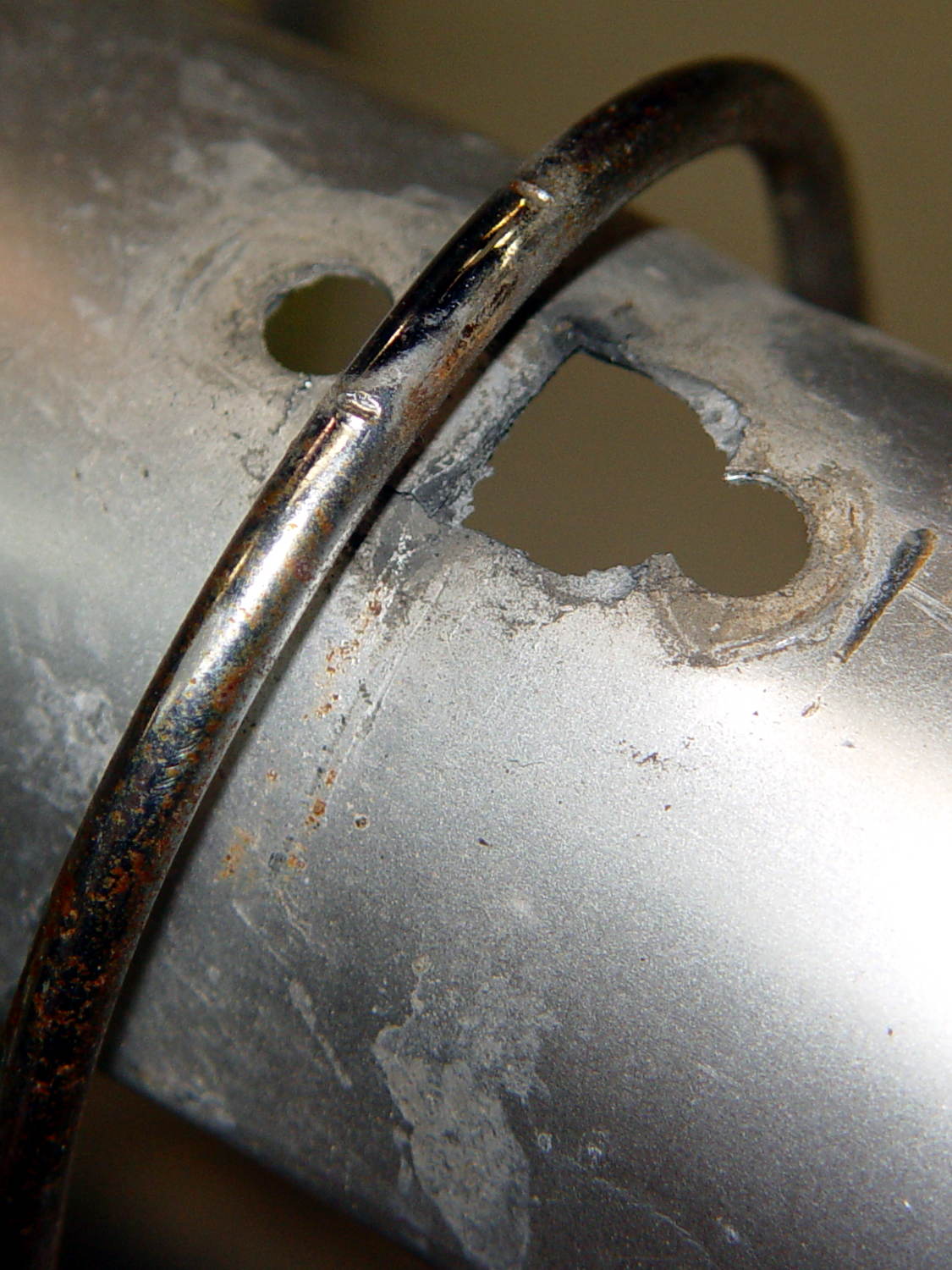
We agreed that repairing the failed flag ferrule made the trailer much quieter, but it still seemed far more rattly than we remembered. It just had to be the fender, somehow, and eventually this appeared:
BOB Yak Fender Mount – fractures
The obviously missing piece of the fender fell out in my hand; the similar chunk just beyond the wire arch fell out after I took the pictures. Yes, the wire has indented the fender.
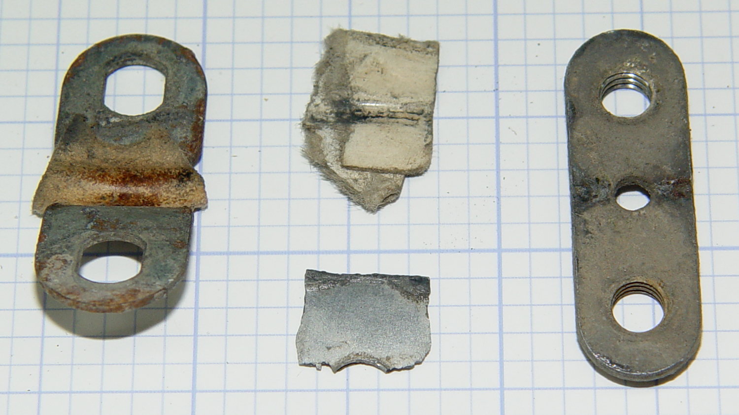
The arch supports the aluminum fender, with a pair of (flat) steel plates clamping the wire to the fender:
BOB Yak Fender Mount – screw plates and pads
The cardboard scraps show I fixed a rattle in the distant past.
Being aluminum, the fender can’t have a replacement piece brazed in place and, given the compound curves, I wasn’t up for the requisite fancy sheet metal work.
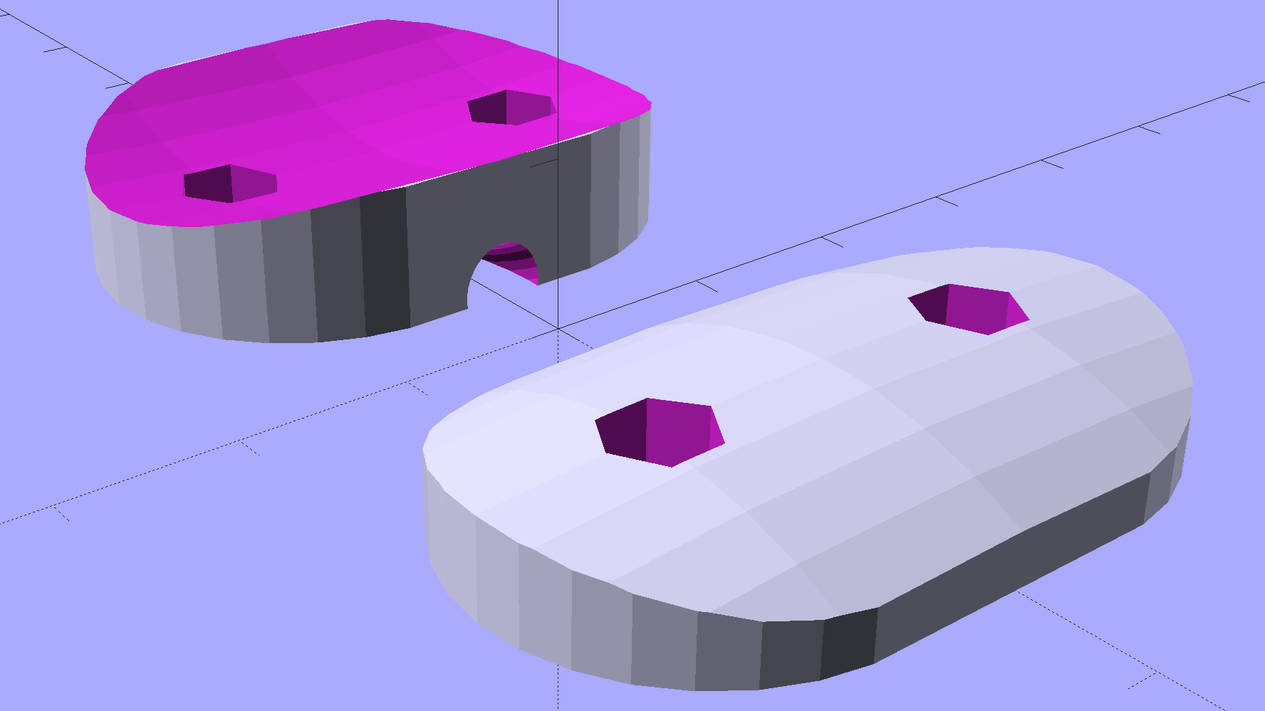
Instead, a bit of math produces a pair of shapes:
BOB Yak Fender Mount – solid model
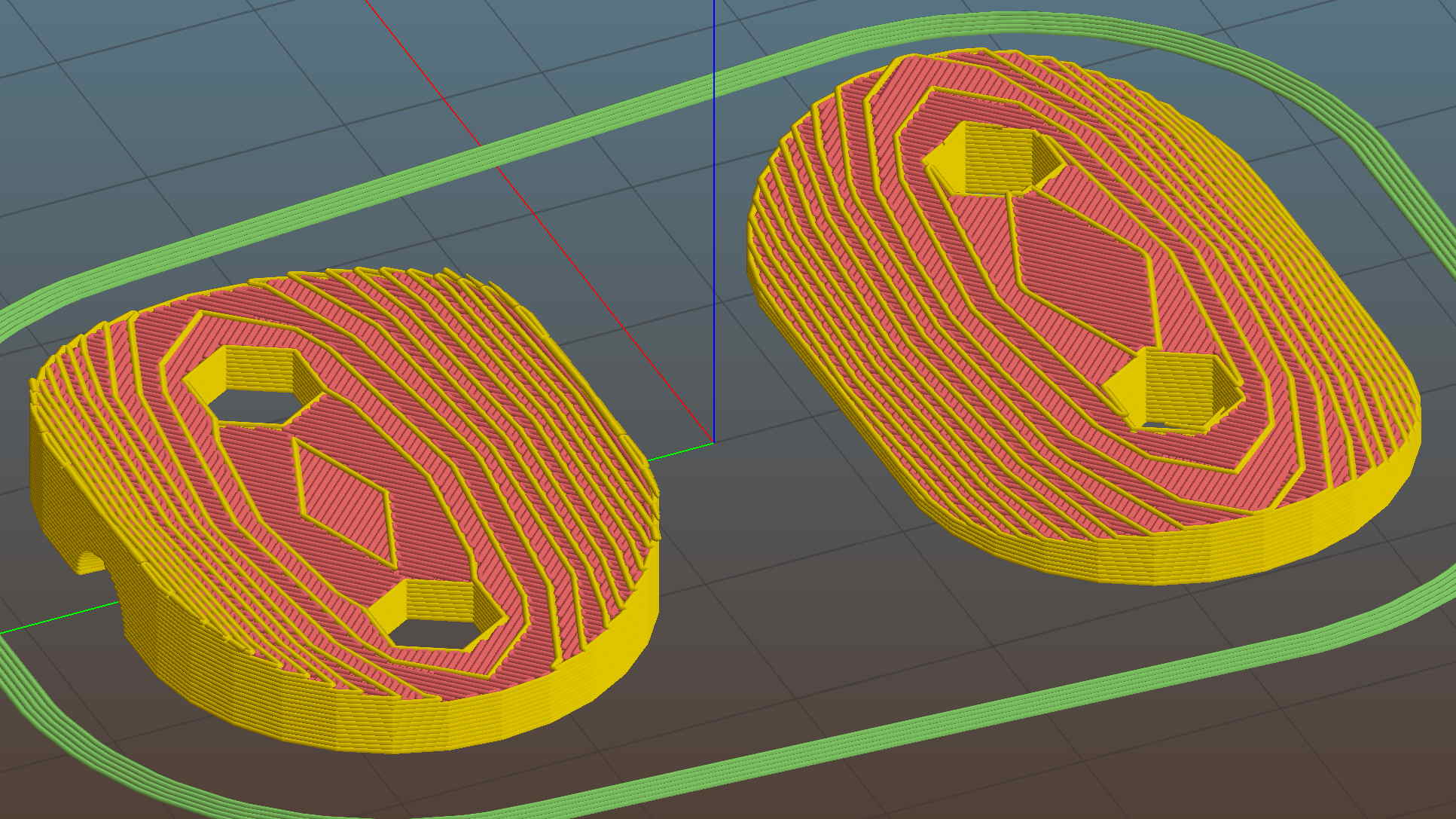
In this case, we know the curve radii, so the chord equation gives the depth of the curve across the (known) width & length of the plates; the maximum of those values sets the additional thickness required for the plates. The curves turn out to be rather steep, given the usual layer thickness and plate sizes, which gives them a weird angular look that absolutely doesn’t matter when pressed firmly against the fender:
BOB Yak Fender Mount – Slic3r preview
The computations required to fit Hilbert Curve surface infill into those small exposed areas took basically forever; given that nobody will ever see them, I used the traditional linear infill pattern. A 15% 3D Honeycomb interior infill turned them into rigid parts.
The notch in the outer plate (top left, seen notch-side-down) accommodates the support wire:
BOB Yak Fender Mount – outer
The upper surface would look better with chamfered edges, but that’s in the nature of fine tuning. That part must print with its top surface downward: an unsupported (shallow) chamfer would produce horrible surface finish and life is too short for fussing with support. Given the surrounding rust & dings, worrying about aesthetics seems bootless.
The original screws weren’t quite long enough to reach through the plastic plates, so I dipped into my shiny-new assortment of stainless steel socket head cap screws. Although the (uncut) M5x16 screws seem to protrude dangerously far from the inner plate, there’s another inch of air between those screws and the tire tread:
BOB Yak Fender Mount – inner
Given the increase in bearing area, that part of the fender shouldn’t fracture for another decade or two.
I loves me my M2 3D printer …
The OpenSCAD source code as a GitHub Gist:
This file contains hidden or bidirectional Unicode text that may be interpreted or compiled differently than what appears below. To review, open the file in an editor that reveals hidden Unicode characters.
Learn more about bidirectional Unicode characters
At some point along a recent grocery ride, the top half of the flag mast on the BOB Yak trailer went missing.
We had a general idea of where it happened, but, fortunately, I Have The Technology:
This slideshow requires JavaScript.
The flag and pole ended up just off the road, only slightly the worse for wear. I hadn’t planned on riding two dozen miles on a rather hot and humid summer day, but so it goes.
The lower ferrule chafed away enough of the fiberglass pole that it could slip downward, eventually releasing the upper ferrule:
BOB Yak Flag – ferrule chafing
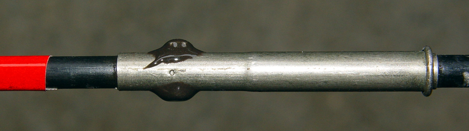
That split near the end enlarged the pole enough that the ferrule couldn’t slide off, so I contented myself with cross-drilling the whole affair for a 1-72 screw, packing epoxy into the hole, tucking more epoxy up inside the bottom end of the ferrule, then burying the screw and nut:
BOB Yak Flag – reassembled ferrule
While I had it on the bench, I replaced the somewhat shredded fluorescent orange tape just under the flag and added a strip of diagonally striped red-and-white retroreflective tape for an attractive barber-pole appearance.
Although you should remove the lathe from the chip pan and do it right, I gimmicked up a reducer for the long drill extension that, IIRC, came with the house:
LMS mini-lathe – drill bit extension
I figured that would be close enough, given the starting situation. The cast iron frame is perhaps half an inch thick at that point, with steel brackets bolted to the far side, so use the hole as a guide and don’t drill with wild abandon.
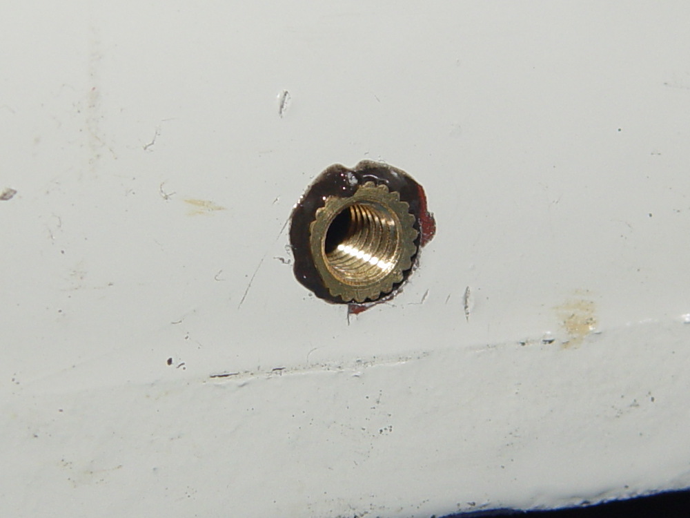
A long M4 screw serves to align the insert eyeballometrically perpendicular to the surface while the JB Kwik epoxy cured:
LMS mini-lathe – insert alignment
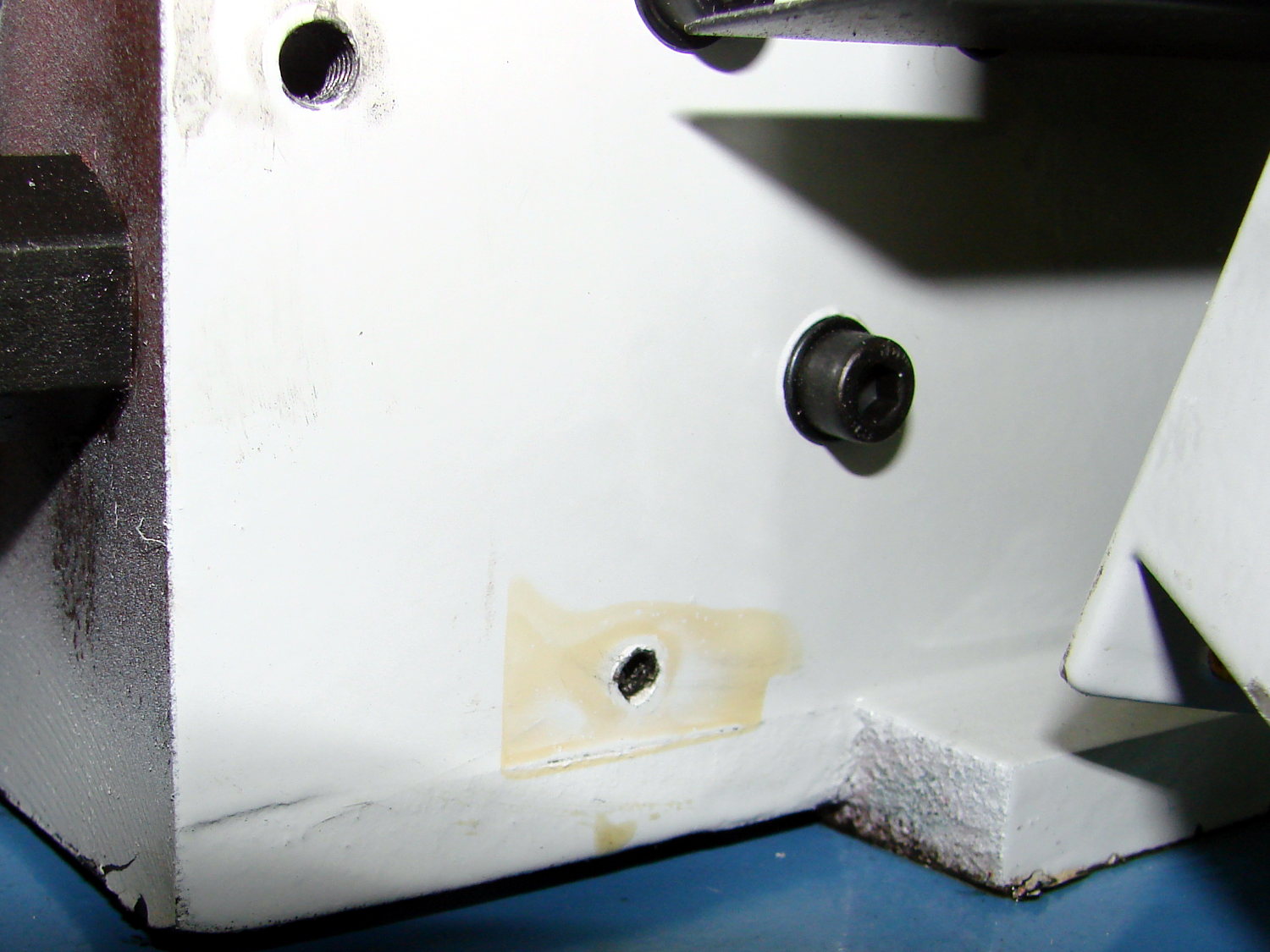
It definitely doesn’t look like it grew there and, indeed, looks like the obvious repair job it is:
LMS mini-lathe – insert epoxied
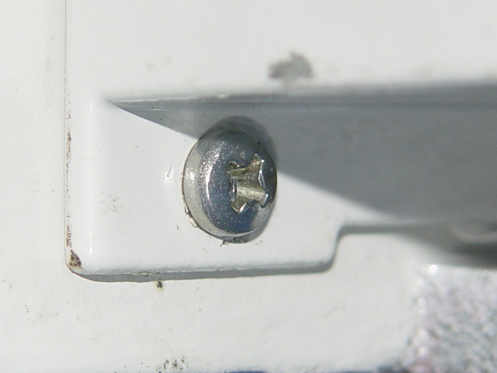
I thought about replacing all the screws, but decided it was so well hidden that, if I didn’t tell anybody, they’d never know:
New hawks must somehow learn that swooping across roadways doesn’t work like swooping across lawns:
Road-killed hawk – Red Oaks Mill – 2016-07-04
We think one of “our” new Cooper’s Hawks didn’t survive its lesson.
That’s the third dead hawk we’ve seen on recent rides; it’s been a rough few weeks for new hawks. Mary also spotted a smashed owl along one of her routes.
Yeah, they’re just birds, but …
Cropped and tweaked from a Sony HDR-AS30V helmet camera image.