The Smell of Molten Projects in the Morning

Ed Nisley's Blog: Shop notes, electronics, firmware, machinery, 3D printing, laser cuttery, and curiosities. Contents: 100% human thinking, 0% AI slop.

Author: Ed

  • Makergear M2: Nozzle Z Offset Recalibration

    After a few days of downtime, an Official Makergear Thermistor arrived and is now installed amid a dab of heatsink compound:

    M2 - Thermistor with heatsink compound
    M2 – Thermistor with heatsink compound

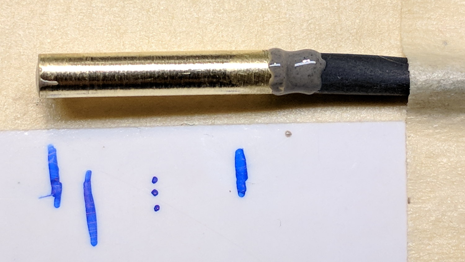
    With the hot end set a bit higher than usual, position the platform at Z=0, lower the nozzle to be flat on the platform, tighten the lock screw, then run off a set of large calibration squares:

    M2 - Nozzle Z Offset Recal - first test
    M2 – Nozzle Z Offset Recal – first test

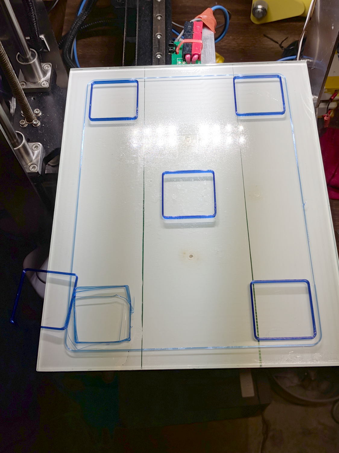
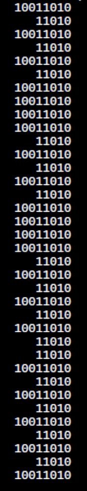
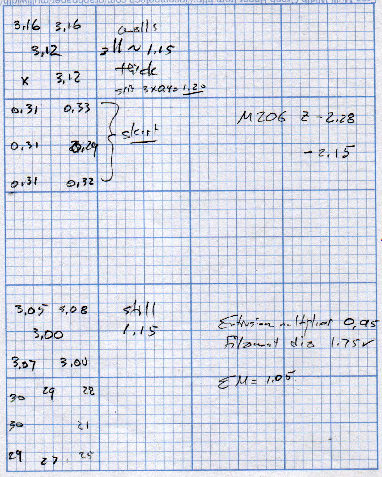
    The scrambled square in the front left says the Z=0 nozzle position came out just a bit too far above the platform and, indeed, the measurements (upper left numbers) say it’s off by 0.15-ish mm:

    M2 Nozzle and Platform Re-Cal Measurements
    M2 Nozzle and Platform Re-Cal Measurements

    Probably a little PETG stuck to the nozzle; I hate adjusting things when they’re burning hot.

    The walls are also thin by a smidge, but the first order of business is to reset the Z offset with M206 Z=-2.15. With that in hand, the second set of squares came out at 3.00 to 3.08 mm (lower left numbers), which I defined to be Close Enough.

    The 0.08 mm variation across the platform isn’t enough to worry about.

    The first skirt threads were too thick and not solidly bonded together, but the second skirt came out normally, with a thickness from 0.21 through 0.30, which is also Good Enough.

    The three-thread walls were still 1.15 mm, rather than 1.20 mm, so the EM should go from 0.95 to 0.95*1.20/1.15 = 1.05.

    Next, a set of single-thread thinwall boxes to verify the Z offset and recheck the Extrusion Multiplier:

    M2 - Nozzle Z Offset Recal - thinwall test
    M2 – Nozzle Z Offset Recal – thinwall test

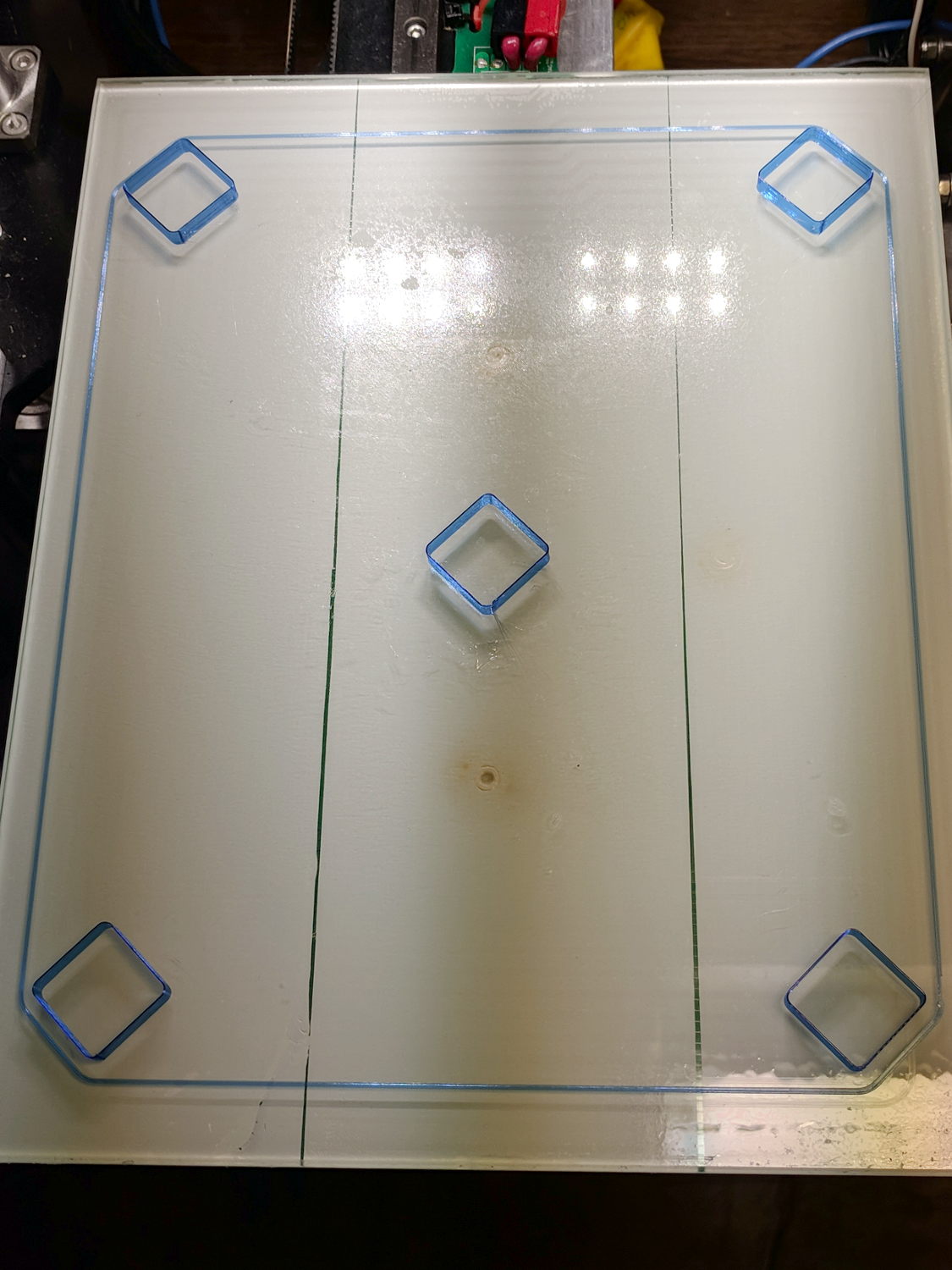
    They’re dead on 3.00 mm tall, varying by not enough to worry about.

    Their single-thread walls are 0.38 mm, not the intended 0.40, which suggests the EM should become 0.95*0.40/0.35 = 1.00.

    It turns out the filament diameter at this part of the roll is scant of 1.75 mm, maybe 1.73 mm, so I decided to not fiddle with the EM.

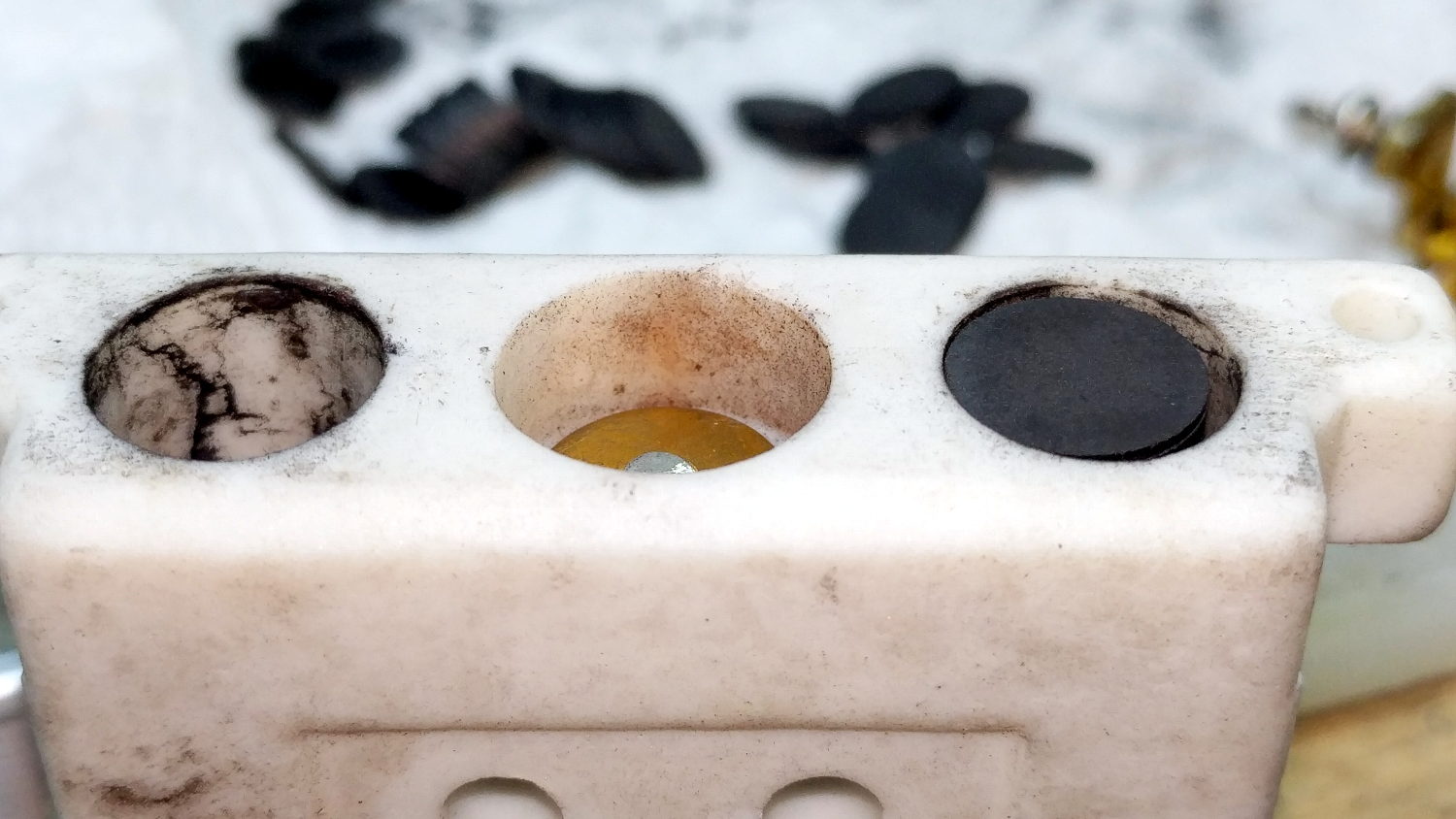
    The first production part came out fine:

    M2 - Nozzle Z Offset Recal - DRL Clamp
    M2 – Nozzle Z Offset Recal – DRL Clamp

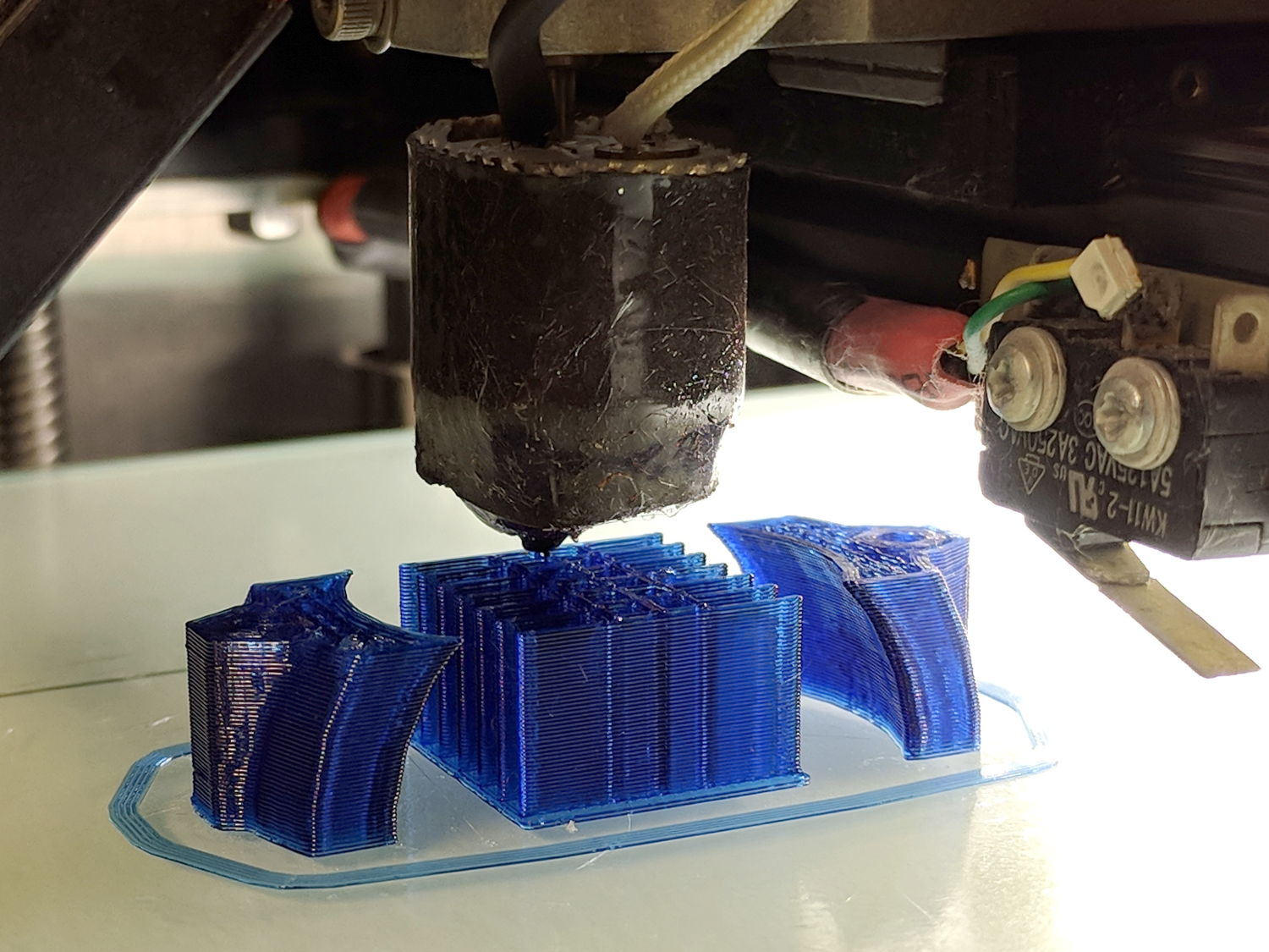
    The flange around the bottom of the arch support grid (in the middle) is intentional; it’s not an overstuffed first layer. The clamp sections rise from the platform just like they grew there.

    So the M2 is back in operation and I have a spare thermistor on the shelf!

  • M2 DIY Thermistor Rebuild: Autopsy

    Not much to my surprise, my hack-job thermistor rebuild went bad:

    M2 - thermistor - assembly 2
    M2 – thermistor – assembly 2

    Having nothing to lose, I heated the brass tube over a butane flame to wreck the epoxy, which blew out with a satisfactory bang and filled the Basement Laboratory with The Big Stink.

    Much to my surprise, the active ingredient still worked:

    M2 DIY thermistor corpse
    M2 DIY thermistor corpse

    The multimeter reported absolutely no intermittent dropouts for as long as I was willing to watch the trace while doing other things:

    DIY Thermistor Autopsy - Resistance Trend
    DIY Thermistor Autopsy – Resistance Trend

    So it must be my crappy soldering technique.

    A brace of real M2 thermistors will arrive shortly …

  • Raspberry Pi 3 I2C vs. Bosch BNO055 Absolute Orientation Sensor

    I’ve been coaching a high-school student (and his father!) on the intricacies of building a self-balancing robot; they’re doing all the hard work and I’m running interference with techie bugs. This one turned out to be particularly nasty.

    It seems all versions of Raspberry Pis have an I2C bus hardware problem preventing them from working correctly with Adafruit’s Bosch BNO055 (yes, “bee en oh zero five five”) Absolute Position Sensor. The problem has been variously diagnosed as being due to the Pi’s inability to handle clock stretching in arbitrary parts of the I2C transaction and the BNO055 chip’s exquisite sensitivity to I2C bus levels, but it’s worse than that.

    Reading the chip’s temperature sensor once every second produced this output:

    BNO055 Sensor - Temperature Register vs I2C
    BNO055 Sensor – Temperature Register vs I2C

    He now knows why you must always leading-zero-fill binary values.

    The shorter values say the chip ran at 26 °C, which means the longer values have a bogus binary 1 in bit 7. I2C bus transfers proceed MSB-first, so the Pi occasionally reads a bogus 1 at the first clock transition while reading the single temperature byte from the BNO055.

    After some flailing around, we observed two types of I2C bus transactions.

    Without clock stretching:

    BNO055 - Normal I2C transaction
    BNO055 – Normal I2C transaction

    With clock stretching:

    BNO055 - Clock-stretched I2C transaction
    BNO055 – Clock-stretched I2C transaction

    Contrary to what one might think from the lead-in description, the non-stretched version always produces the incorrect leading bit and the stretched version usually delivers the correct result.

    He had previously installed the clock stretch workaround and we verified it was active. Turning it off had no effect, as did turning it back on again. The value uses units of the SCL period, so the modified value of 20000 produces 20×103 counts of 1/(100 k bit/s) = 2 s, far longer than any delay we observed. In fact, the default 640 μs would (apparently) suffice for the BNO055.

    I installed the Adafruit-recommended pullup resistors and we verified they had no effect.

    We noticed, but I did not record, nasty positive-going pulses on both SDA and SCL which were not due to noise or supply problems. As far as I can tell, the Pi does not maintain control over the I2C bus lines during some phases of the transaction, perhaps when the BNO055 invokes clock stretching, allowing the pullups to produce narrow upward glitches crossing the logic threshold. This will merit further study.

    The solution, such as it is, seems to require slowing the I2C bus transactions to 25 kb/s, by inserting a line in the /boot/config.txt file:

    dtparam=i2c_arm_baudrate=25000
    ... dummy line to reveal underscores ...

    Slowing to 50 kb/s produced intermittent errors, while 25 kb/s seemed to completely eliminate them. This contradicts suggestions of proper operation at any speed other than the default 100 kb/s. Note: this applies to a single-byte data value and longer transactions remain to be tested.

    I want to verify that the lower rate also eliminates the glitches, which will require running the Pi with the scope plumbed into its guts for some time. For obvious reasons, he’d rather get the robot working, so, until he encounters more problems, I won’t see the hardware …

    Update: There’s now a way to do I²C with software bit-banging in a reasonably easy way. Thanks to Simon Blake for pointing this out!

  • Kenmore Model 158 Pedal: Graphite Disk Refill

    The pedal on one of Mary’s Kenmore Model 158 sewing machines lost most of its speed control abilities, which past experience has shown indicates its carbon / graphite disks have deteriorated. Fortunately, I still have a supply of disks from the Crash Test Dummy machine and have gotten pretty good at dismantling the pedal housing.

    While I had the pedal apart, I filed the brass contact plates smooth again:

    Kenmore 158 Pedal - graphite disk contact
    Kenmore 158 Pedal – graphite disk contact

    Most of the deterioration happens within half a dozen disks snuggled up against those contacts, a few more on the other end of the stack against the graphite button applying the pressure, and an occasional grimy disk in the middle of the stack.

    I filled both stacks flush to the top of the ceramic housing, then removed one disk from each to let the brass contacts slightly compress the stacks:

    Kenmore 158 Pedal - graphite disk refill
    Kenmore 158 Pedal – graphite disk refill

    A quick test showed the control range started a bit too fast, so I removed one more disk from the stacks, buttoned it up, and it’s all good again: a slow start with a good range.

  • eBay High Voltage Alligator Clip Test Leads

    The Description sounds enticing, in the usual eBay manner:

    100% Brand new and high quality.
    Product Shape: Same as the picture show
    1. Product Name: High Voltage Alligator Clip Test Leads
    2. Cable Type: Double-Ended Wire
    3. Conductor Material& Size: 1mm²Copper Wires
    4. Housing Material: Silicone
    5. Max. Current: 15A
    6. Withstanding Voltage: 2KV
    7. Operating Temperature: -20℃~120℃
    8. Making Way: Injection Molding
    9. Interface Type: AC/DC
    10. Color: Black, Yellow, Red, Green, Blue

    Suit For:
    1. Injection molding to complete, good looking, moisture proof, durable and tough!
    2. Electrical test leads suitable for use with multimeters, power supplies and other electronic equipment

    They’re three bucks each, which should buy you some copper and decent construction.

    The insulation over the clips is certainly chunky enough, even if one might quibble about the standoff distance required for a 2 kV rating:

    eBay HV Alligator Clips - overview
    eBay HV Alligator Clips – overview

    The wires have good silicone insulation and consist of fine copper strands, but I definitely won’t trust them to handle 2 kV:

    eBay HV Alligator Clips - wiring
    eBay HV Alligator Clips – wiring

    No solder, of course, just  copper conductors bent back around the insulation and crimped into the alligator clip. Definitely not a gas-tight metal-to-metal joint, but good enough for simple needs.

    Update: A better look at the crimp on a different clip:

    eBay HV Alligator Clips - crimp
    eBay HV Alligator Clips – crimp

    IMO, the clip’s low-strength metal can’t possibly make and hold a gas-tight joint, no matter how hard you squeeze.

    There’s enough contact area for low resistance, on the order of a few tens of milliohms. We’ll see how long this lasts …

  • Sinking of the USS President Coolidge: Photo Source

    While staying at the Witherup House in Franklin PA, I found :

    Colliers Photographic History of World War II - cover
    Colliers Photographic History of World War II – cover

    It was published in 1946, when memories were fresh and ISBNs hadn’t yet been invented:

    Colliers Photographic History of World War II - copyright 1946
    Colliers Photographic History of World War II – copyright 1946

    Paging through it, I found a photo similar to one I’d grown up with (clicky for more many dots):

    USS President Coolidge - Abandon Ship - Colliers Photographic History of World War II
    USS President Coolidge – Abandon Ship – Colliers Photographic History of World War II

    None of those guys look like Dad.

    Many of the events in World War II made little sense until the declassification of the Enigma decryptions and the ensuing Ultra / Magic programs showed the value of weaponized math …

  • Houses Are Trouble: Trees vs. Winds

    A loud crack during a windy thunderstorm announced this mess:

    Driveway branch - as fallen
    Driveway branch – as fallen

    Some deft bow saw work cut it down to size:

    Driveway branch - trimmed
    Driveway branch – trimmed

    Whereupon our neighbor arrived home and we dragged the carcass off the driveway.

    Fortunately, it missed everything important, as have several recent branch falls in our yard. The same cannot be said for the many downed trees around the immediate area from recent storms; some folks are hurtin’ bad.

    Verily, houses (and trees) are trouble!