The Smell of Molten Projects in the Morning

Ed Nisley's Blog: Shop notes, electronics, firmware, machinery, 3D printing, laser cuttery, and curiosities. Contents: 100% human thinking, 0% AI slop.

Author: Ed

  • Subaru Forester Rear Wiper Disassembly

    You’re supposed to just rotate the wiper blade holder and have it pop out of the mount on the end of the arm:

    Subaru Forester - rear wiper blade mount
    Subaru Forester – rear wiper blade mount

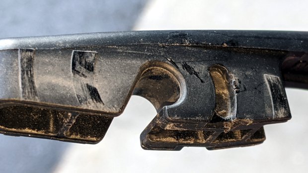
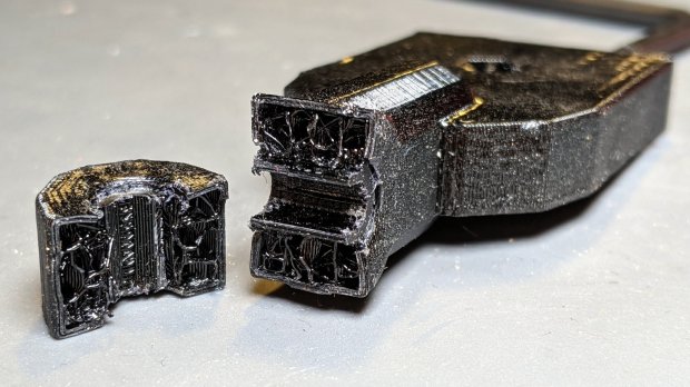
    The blade holder has two opposed pegs fitting into those curved notches to the right of the hook for the holder’s pivot, with the intent of preventing it from rotating too far and sliding out. I was unwilling to apply sufficient force to disengage those pegs, as the penalty for breaking the wrong piece of plastic seemed very high. Apparently, the pegs should ride up over the slightly lower edge of their notch, bending the holder’s sides outward as they do.

    So I jammed a little screwdriver beside one of the pegs, managed to encourage it out of its notch, repeated the treatment on the other side, and the blade holder popped right out.

    The front wiper arms have J-hooks on their ends and disengage easily, at least after you realize the flat panel on the blade holder is actually a latch you’re suppose to pull up-and-out to release the hook. This goes more easily when assisted with the aforementioned small screwdriver.

    The blades were in good shape after five years, mostly because the Forester spends most of its time in the garage. A trio of silicone wipers should last the rest of its life, with the OEM wipers tucked into the spare tire well Just In Case.

    Back in the day, one could replace just the blades, not the entire holder, but I suppose this is progress.

  • CNC 3018XL: Pilot V5RT Pen Holder Lock Screw

    Flushed with success about the MPCNC drag knife locking screw, I installed a similar screw on the V5RT pen holder for the CNC 3018:

    Pilot V5RT holder - lock screw insert - assembled
    Pilot V5RT holder – lock screw insert – assembled

    A dark ring of epoxy around the screw holds a shortened M3 brass insert in place:

    Pilot V5RT holder - lock screw insert
    Pilot V5RT holder – lock screw insert

    As it turned out, the original recess left only a few threads for the M3 SHCS, so the much longer screw wobbulated alarmingly. I drilled out the threads, turned the knurls off the insert, shortened it a bit, masked the pretty knurls on the aluminum ring, then glopped the insert in place while the Sherline held the screw vertical:

    Pilot V5RT holder - insert epoxy
    Pilot V5RT holder – insert epoxy

    While I was at it, I added a thin ring of foam rubber under the knurled ring to keep it from clacking against the upper bushing.

    Now I can’t lose the hex wrench when I take the thing out for Show-n-Tell sessions …

  • Raspberry Pi Shutdown / Start Button

    While adding the usual Reset button to a Raspberry Pi destined for a Show-n-Tell with the HP 7475A plotter, I browsed through the latest dtoverlay README and found this welcome surprise:

    Name:   gpio-shutdown
    Info:   Initiates a shutdown when GPIO pin changes. The given GPIO pin
            is configured as an input key that generates KEY_POWER events.
            This event is handled by systemd-logind by initiating a
            shutdown. Systemd versions older than 225 need an udev rule
            enable listening to the input device:
    
                    ACTION!="REMOVE", SUBSYSTEM=="input", KERNEL=="event*", \
                            SUBSYSTEMS=="platform", DRIVERS=="gpio-keys", \
                            ATTRS{keys}=="116", TAG+="power-switch"
    
            This overlay only handles shutdown. After shutdown, the system
            can be powered up again by driving GPIO3 low. The default
            configuration uses GPIO3 with a pullup, so if you connect a
            button between GPIO3 and GND (pin 5 and 6 on the 40-pin header),
            you get a shutdown and power-up button.
    Load:   dtoverlay=gpio-shutdown,<param>=<val>
    Params: gpio_pin                GPIO pin to trigger on (default 3)
    
            active_low              When this is 1 (active low), a falling
                                    edge generates a key down event and a
                                    rising edge generates a key up event.
                                    When this is 0 (active high), this is
                                    reversed. The default is 1 (active low).
    
            gpio_pull               Desired pull-up/down state (off, down, up)
                                    Default is "up".
    
                                    Note that the default pin (GPIO3) has an
                                    external pullup.
    
            debounce                Specify the debounce interval in milliseconds
                                    (default 100)

    So I added two lines to /boot/config.txt:

    dtoverlay=gpio-shutdown
    dtparam=act_led_trigger=heartbeat

    The fancy “Moster heatsink” case doesn’t leave much room for wiring:

    RPi Shutdown Restart Switch - GPIO 3
    RPi Shutdown Restart Switch – GPIO 3

    The switch button is slightly shorter than the acrylic sheet, so it’s recessed below the surface and requires a definite push to activate. It’s not as if it’ll get nudged by accident, but ya never know.

    I’ll eventually migrate this change to all the RPi boxes around the house, because it just makes more sense than any of the alternatives. Heck, it’ll free up a key on the streaming radio player keypads, although I must move the I²C display to Bus 0 to avoid contention on Pin 3.

    For reference, the Raspberry Pi header pinout:

    Raspberry Pi pinout
    Raspberry Pi pinout

    I don’t know if I²C Bus 0 has the same 1.8 kΩ pullups as Bus 1, though; a look at the bus currents will be in order.

  • Homage Tek CC Cursor: Pivot Milling

    A test to mill the pivot hole in 0.5 mm PETG sheet worked perfectly:

    Tek CC - cursor pivot hole milling
    Tek CC – cursor pivot hole milling

    The cutter is a 3.175 mm = 1/8 inch router bit, one of a ten-pack that came with the CNC 3018 and to which I have no deep emotional attachment, held in a collet in the Sherline. The hole is 5.5 mm to fit an eyelet. The PETG is taped to a thin plywood scrap.

    The hole happened by feeding G-Code manually into LinuxCNC, after touching off XYZ=0 at the center of the pivot and jogging up a bit:

    g0 y-1.1625
    f1000
    g0 z0.5
    g2 p5 z-1.5 i0 j1.1625

    Yes, I engraved the hairline using a diamond drag tool on the CNC 3018, cut the cursor outline with a drag knife on the MPCNC, then milled the pivot hole on the Sherline. This seems way over the top, even to me, but that’s just how the tooling worked out right now.

    In actual practice, I’d probably mill a stack of cursors and pivot holes on the Sherline in one setup, then engrave the hairlines in a suitable fixture. I think I know enough to fit a spring-loaded diamond drag bit into the Sherline’s 10 mm ID spindle or, worst case, conjure a block for the Z-axis carrier in place of the entire spindle mount.

    At least now I can remember what I did to make the hole.

  • MPCNC Drag Knife Holder: Lock Screw

    While calibrating the MPCNC’s probe camera offset for the drag knife holder, this happened:

    Drag Knife - vertical escape
    Drag Knife – vertical escape

    Well, at least it’s centered on the target:

    Drag Knife - vertical escape - detail
    Drag Knife – vertical escape – detail

    This happened a few times before, because my fingers don’t fit neatly inside the drag knife holder to tighten the lock ring:

    Drag Knife - LM12UU ground shaft - assembled
    Drag Knife – LM12UU ground shaft – assembled

    [Update: The lock ring keeps the holder at a fixed position inside the 12 mm shaft and doesn’t affect the blade directly. When the ring works loose, the threaded holder can rotate to expose more blade and, in this case, stab deeper into the target. ]

    So I turned & knurled an aluminum ring, then tapped a 3×0.5 mm hole for a lock screw plucked from the Drawer o’ Random M3 Screws:

    Drag Knife - lock screw - side
    Drag Knife – lock screw – side

    A view looking along the screw shows a bit more detail around the spring:

    Drag Knife - lock screw - front
    Drag Knife – lock screw – front

    The general idea is to set the blade extension, then tighten the lock screw to hold it in place, without relying on the original brass lock ring, shown here while cutting a boss for the spring:

    Drag Knife - turning spring recess
    Drag Knife – turning spring recess

    The lock screw’s knurled handle just barely kisses the NPCNC’s black tool holder ring, so my guesstimated measurements were a bit off. Clamping the knife holder one itsy higher in the tool holder solved the problem.

    I cranked on 300 g of spring preload and, squashed like that, the spring’s rate is now 75 g/mm. Cutting at Z=-1 mm should suffice for laminated paper slide rule decks.

    The original sizing doodle:

    Drag Knife Holder - lock screw ring doodle
    Drag Knife Holder – lock screw ring doodle

    The short 18 mm section clears the inside of the LM12UU bearing, although it could be a millimeter shorter. The 19 mm section comes from the 3/4 inch aluminum rod I used, skim-cut to clean it up.

    If I ever remake this thing, it needs a major re-think to get all the dimensions flying in formation again.

  • Baofeng Bike Helmet Headset Wiring Repair

    The audio output wire from the Baofeng UV-5R to my bike helmet headset adapter broke after a year and a half, far longer than I expected:

    Baofeng - broken spkr wire
    Baofeng – broken spkr wire

    It’s the green one, over on the left, pulled out of the heatstink tubing that should have provided some strain relief, having broken at the solder joint to the resistor.

    A quick & easy fix, after which I reapplied even more tape to hold everything in place.

    Maybe it’ll last two years this time around …

  • Photo Lamp Mount: Moah Plastic!

    One of the cold shoe mounts I made for the photo lamps cracked:

    Photo Lamp Mount - fractured
    Photo Lamp Mount – fractured

    It’s done in PETG with my more-or-less standard two perimeter threads and 15% 3D honeycomb infill, which is Good Enough™ for most of my parts. In this case, there’s obviously not nearly enough plastic in there!

    Redoing it with three perimeters and 50% infill should improve the situation, even though it looks identical on the outside:

    Photo Lamp Mount - reinstalled
    Photo Lamp Mount – reinstalled

    I didn’t replace the other mount. If it breaks, it’ll get the same 50% infill as this one. If this one breaks, I’ll try 75%.

    An easy fix!