The Smell of Molten Projects in the Morning

Ed Nisley's Blog: Shop notes, electronics, firmware, machinery, 3D printing, laser cuttery, and curiosities. Contents: 100% human thinking, 0% AI slop.

Author: Ed

  • Tour Easy: Extended V-brake Noodle

    Tour Easy: Extended V-brake Noodle

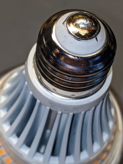
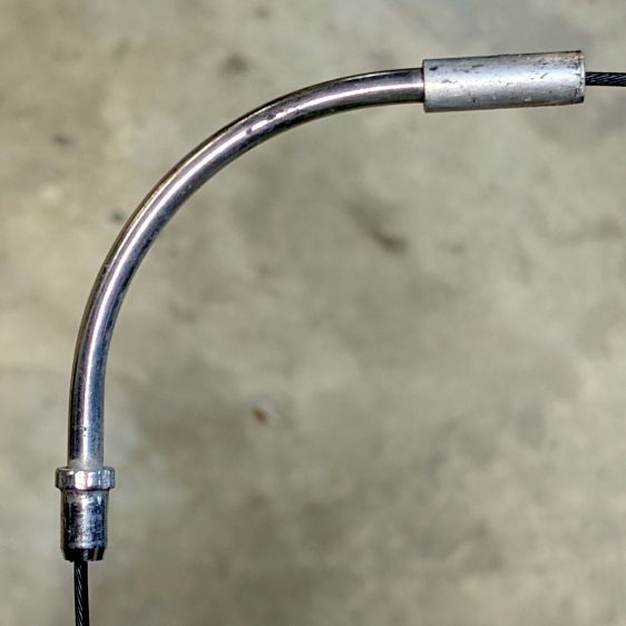
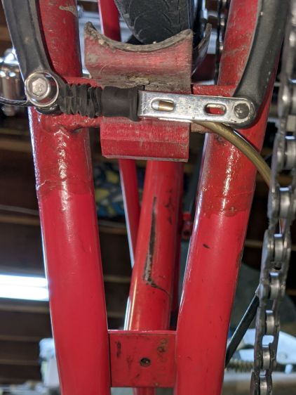
    Although our Tour Easy recumbents use ordinary (*) V-brakes, their frame geometry doesn’t route the rear cable quite the way the brake designers expected. Mary’s Medium-Small frame always had its rear brake cable resting against the frame tube, where it bent slightly as she applied the brakes:

    Tour Easy rear V-brake layout
    Tour Easy rear V-brake layout

    That’s looking up from under the rear wheel, with the bike on a workstand, and, yeah, it’s pretty grubby down there.

    The squashed rubber boot suggests the brake arms are too close together, but that’s where they must be to hold the brake pads in the proper position, even with new pads and big spacer washers. As a result, the cable stop over on the right at the end of the noodle rests against the frame and dings the paint.

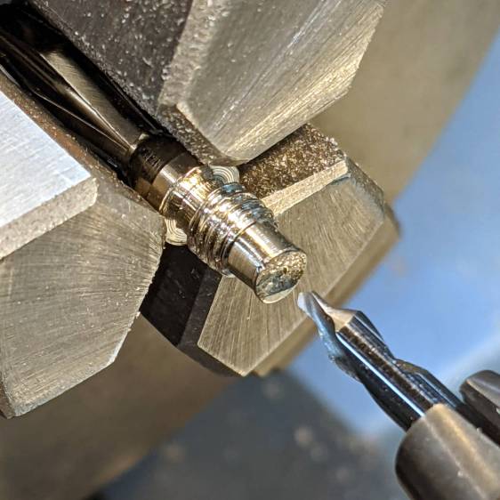
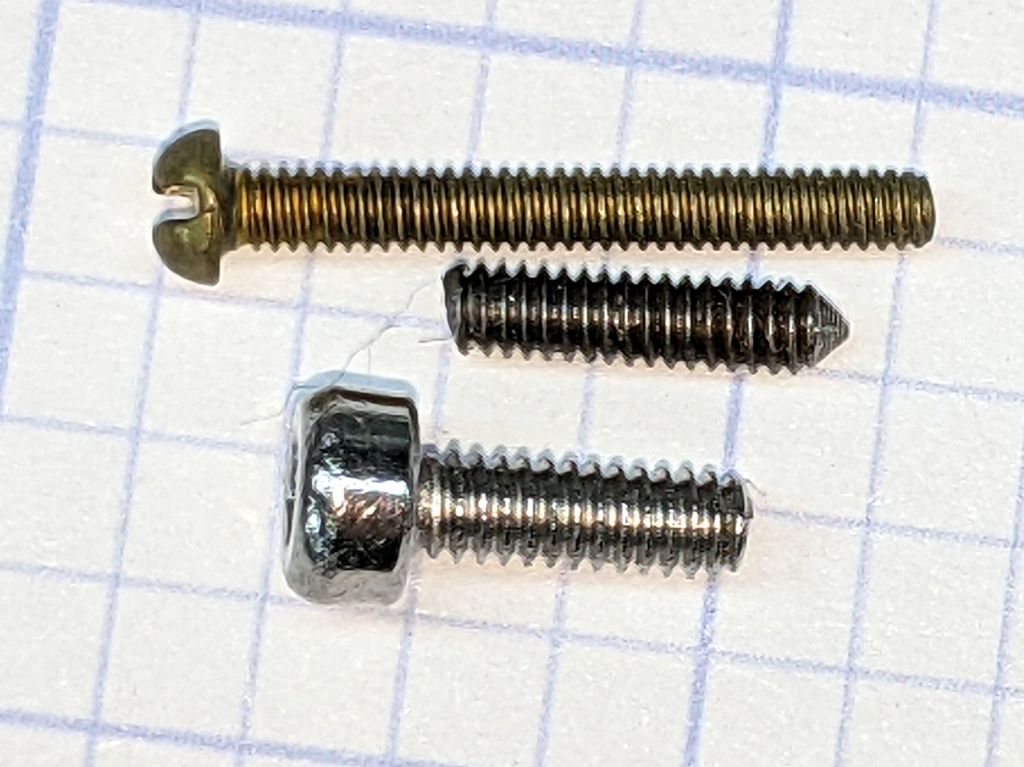
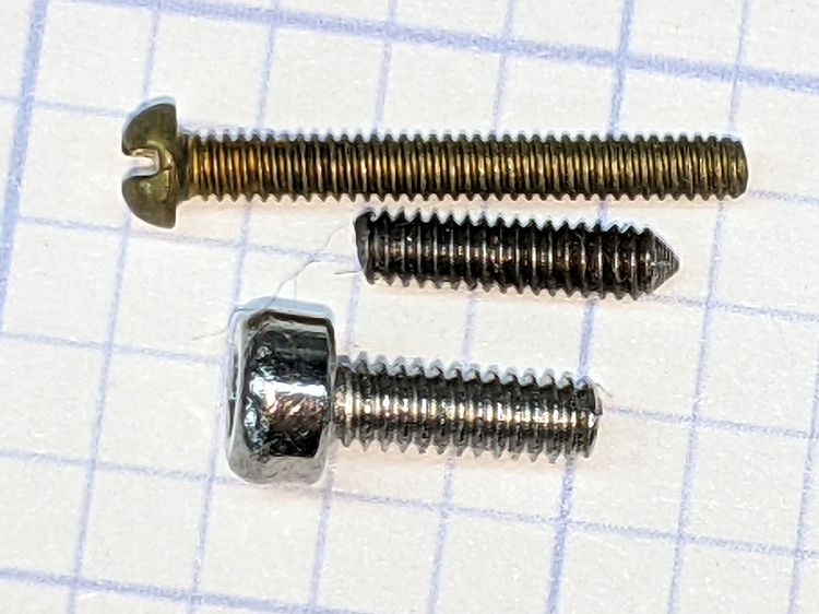
    My first thought was to add some length to the end of the noodle inside the stirrup, so I made an adapter with the ID on the noodle end matching the OD on the fitting end:

    V-brake - larger noodle - end stop adapter
    V-brake – larger noodle – end stop adapter

    Which worked poorly, because the noodle has a straight section leading up to the fitting inside the stirrup; any additional length pushes the noodle curve against the stirrup pivot and cants it out of line:

    Tour Easy rear V-brake noodle
    Tour Easy rear V-brake noodle

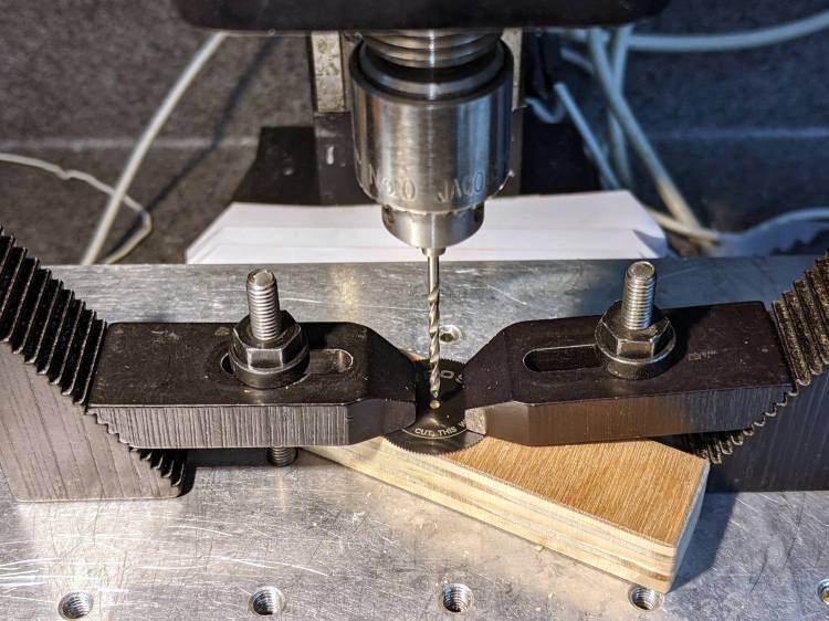
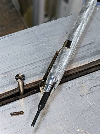
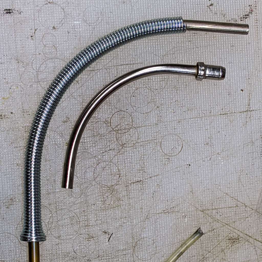
    I’ve been avoiding the fallback plan of building a bigger noodle for years, but finally combined a foot of 3/32 inch brass tubing, a tube bender spring, and various large-diameter round-ish objects from the Basement Warehouse Wing:

    V-brake - larger noodle - bending
    V-brake – larger noodle – bending

    I annealed the tube by running a torch along its length until the color changed to the obvious “I’m hot enough” copper color, then let it air-cool while I did something else. Brass work-hardens quickly and required two more annealings while finishing that smooth curve; as far as I know, brass doesn’t harden with the heat-and-quench cycle used for steel.

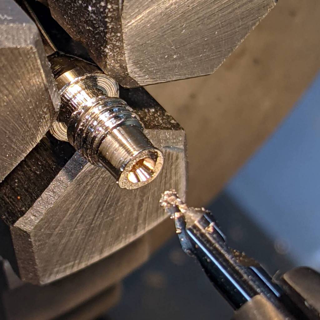
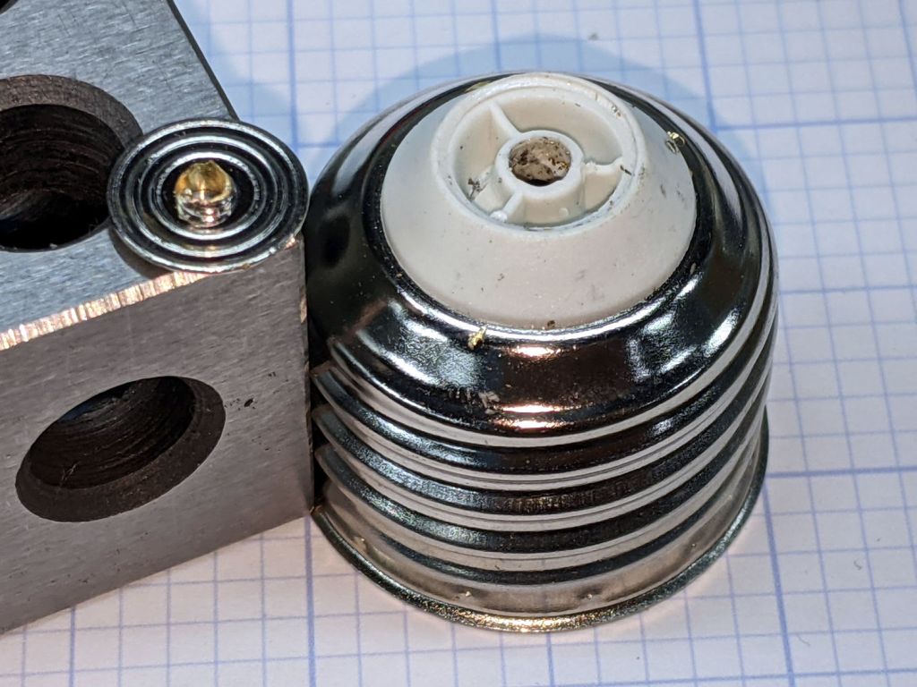
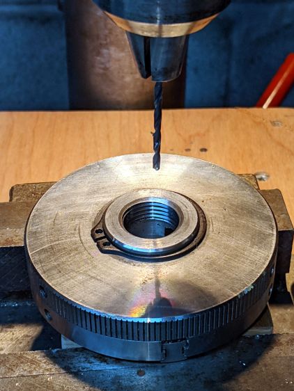
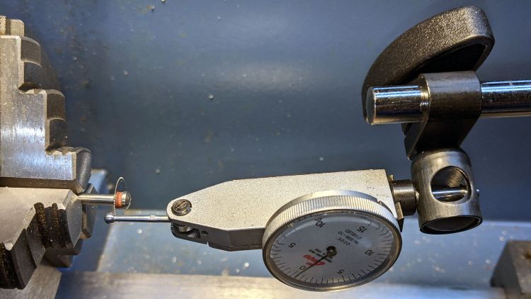
    A little more lathe work produced a replacement fitting:

    V-brake - larger noodle - end stop
    V-brake – larger noodle – end stop

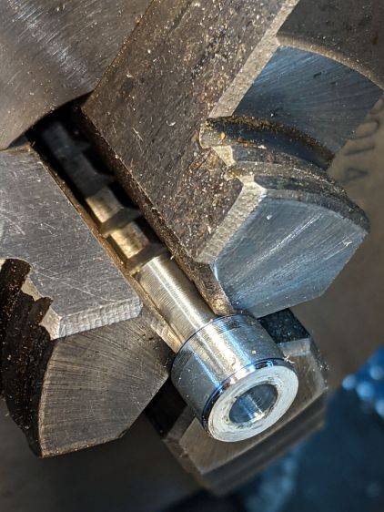
    The hole is barely one diameter deep, but I think it’ll align the tube well enough for my simple needs. The failure will most likely involve having the cable chew through the inward side of the mis-aligned tube, which should become obvious in short order.

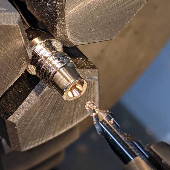
    The fitting on the OEM noodle seems to be crimped in place, but I figure my version is unlikely to fall off in normal use:

    V-brake - larger noodle vs OEM
    V-brake – larger noodle vs OEM

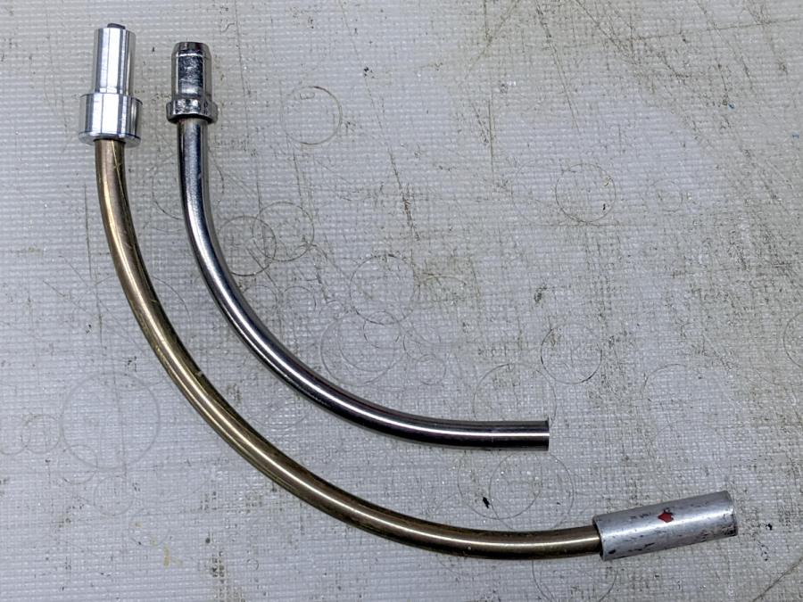
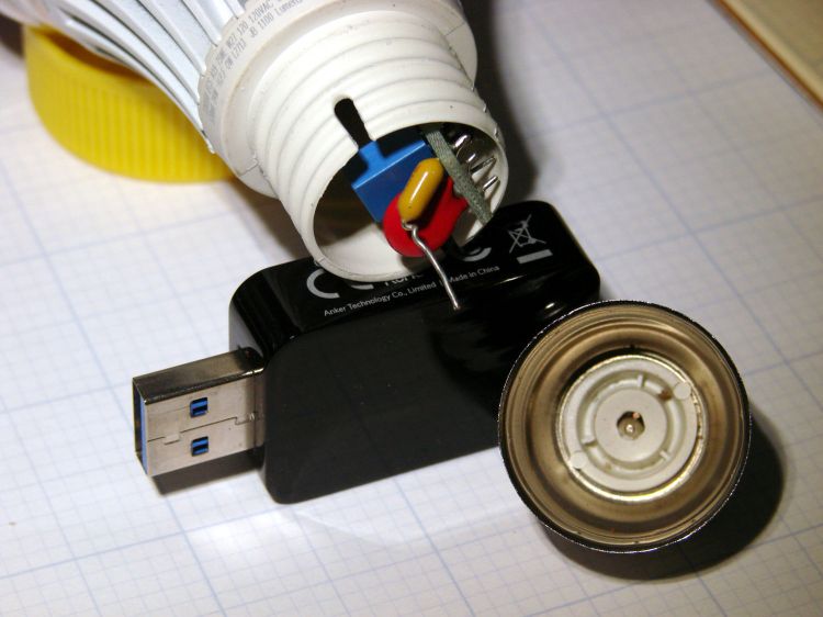
    Lined up thusly, you can see the reduced straight section behind my fitting and the much larger sweep out to the cable stop.

    The OEM noodle had a (presumably) PTFE liner, so I adapted a length of PTFE brake cable liner by mashing the end with various conical objects until it kinda-sorta looked like the cable stop might capture the ragged flange:

    V-brake - larger noodle - PTFE liner
    V-brake – larger noodle – PTFE liner

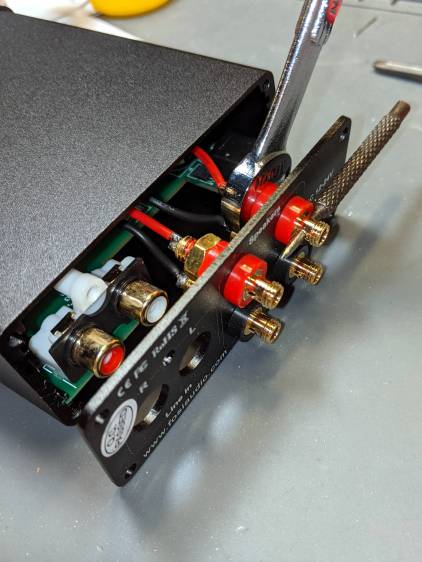
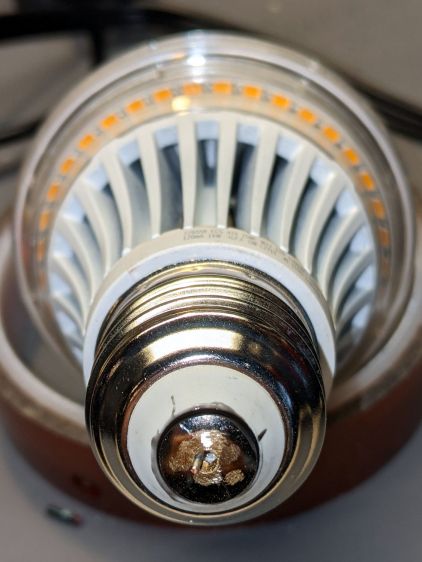
    Reassembling in reverse order produces a comforting sight:

    V-brake - larger noodle - installed
    V-brake – larger noodle – installed

    Despite appearances, the new noodle sits below the frame and well above the chain in normal use. In the most extreme small-small cross gearing position the chain barely clears it, but the takeup arm on the rear derailleur starts clattering enough to remind us not to do that.

    Brass is certainly not as strong as stainless (?) steel, although I think it ended up in a reasonably hard condition after all the bending. I’m certain neither of us can squeeze the brake lever enough to come anywhere close to causing a problem.

    Making a noodle was easier than I expected and, in a month or so, we’ll see how it behaves under actual riding conditions.

    (*) “Ordinary” as of many decades ago, because the design dates back to the mid-70s, when Fast Freddy Markham broke 65 mph on a rather customized Easy Racers Gold Rush.

  • Audio Amp vs. Bananas

    Audio Amp vs. Bananas

    A low-end audio power amp destined for a pair of ancient-yet-still-serviceable speakers arrived, but attempting to poke wires through the side holes of the banana jacks showed they were oriented in random directions. Back in the day, banana jacks had D-shaped shafts fitted into D-shaped panel holes, but those days are gone.

    A few minutes with screwdriver, wrench, and (tiny) punch sufficed to line up the holes for E-Z poking:

    Fosi audio amp - jack alignment
    Fosi audio amp – jack alignment

    Despite the new convenience, I decided to solder banana plugs to the speaker wires, leading to the discovery my few remaining plugs came from the very bottom of the usability barrel:

    Cheap banana plug - solder side
    Cheap banana plug – solder side

    I have no idea how one might affix a wire to that blank stub, but poking a small center drill into the brass lump produces an easily solderable recess:

    Cheap banana plug - center drilled
    Cheap banana plug – center drilled

    Dab with flux, tin, insert wire, add solder, repeat with all four plugs, and I’m set with a boomin’ system.

  • LED Bulb: Mechanical FAIL

    LED Bulb: Mechanical FAIL

    Replacing the second torchiere lamp shade required unscrewing its 100 W equivalent LED bulb, which required far too many turns and eventually felt sufficiently wrong to reveal the problem:

    LED Bulb - unscrewed base
    LED Bulb – unscrewed base

    The entire metal base shell unscrewed from the plastic housing and twisted off the lead from what looks like a PTC fuse in series with the center contact; the cute little pigtail effect suggests I’ve wrecked the epoxy-to-wire seal.

    It had a five year warranty which, alas, expired three years ago. This style of bulb has fallen out of favor, so I may as well get some Quality Shop Time out of it.

    I don’t know how the factory machinery attached the lead to the contact button, but I’m going to go primal on it with some solder. The trick will be soldering it after assembly, so the first step is to drill through the middle of the button.

    Grab it nose-down in the Sherline’s three-jaw chuck, flip it over, grab the chuck in the drill press vise, line it up, center-drill the button, then drill right through that sucker:

    LED Bulb - base drilling setup
    LED Bulb – base drilling setup

    Of course, the contact came loose from the base, because I pretty much drilled right through the rivet flange holding it in place:

    LED Bulb - removed center contact
    LED Bulb – removed center contact

    Nothing a dab of epoxy can’t fix, though. I scuffed up the outside of the contact to remove the nickel (?) plating and expose the underlying brass to improve its solderability.

    After the epoxy cured, align wire with hole, screw the base onto the lamp shell, and it’s ready for soldering:

    LED Bulb - base ready for solder
    LED Bulb – base ready for solder

    The hole is way too large for the wire, but I wasn’t about to wreck a tiny drill on what might have been a weld nugget. In any event, the bigger the blob, the better the job:

    LED Bulb - soldered base
    LED Bulb – soldered base

    Just like light bulb bases used to look, back in the day.

    With a bit of luck, it’ll sit in that socket for another seven years.

    It could happen, ya never know.

  • Torchiere Lamp Shade 2

    Torchiere Lamp Shade 2

    Three and a half years later, the shade on the living room’s other torchiere lamp crumbled at a touch:

    Torchiere Lamp Shade 2 - crumbled
    Torchiere Lamp Shade 2 – crumbled

    Because I live in the future and had solved this problem in the past, eight hours of print time produced a second shade:

    Torchiere Lamp Shade 2 - on platform
    Torchiere Lamp Shade 2 – on platform

    I sliced the same STL file with PrusaSlicer to get G-Code incorporating whatever configuration changes I’ve made to the M2 over the years and include any slicing algorithm improvements; the OpenSCAD code remains unchanged.

    The as-printed shade had pretty much the same crystalline aspect as the first one:

    Torchiere Lamp Shade 2 - no epoxy
    Torchiere Lamp Shade 2 – no epoxy

    Smoothing a layer of white-tinted epoxy over the interior while spinning it slowly in the mini-lathe calmed it down enough for our simple needs, although the picture I tried to take didn’t show much difference.

    That was easy …

  • Gyros Miniature Circular Saw Blade & Mandrel Tinkering

    Gyros Miniature Circular Saw Blade & Mandrel Tinkering

    The Small Envelope o’ Slitting Saw Blades also disgorged several Gryos Ultra-fine blades and their mandrel with a broken screw jammed in place. Unlike similar Dremel-ish cutoff wheels with a mandrel threaded M2×0.4 mm, these blades have a 1/16 inch = 64 mil hole fitting the mandrel’s screw:

    Gyros mandrel - broken screw size
    Gyros mandrel – broken screw size

    The 1-72 brass screw came heartbreakingly close to fitting and the M2 SHCS obviously won’t play. I can’t measure super-fine threads, but I can count: 16 threads on the stub occupy about the same distance as 18 threads on the 1-72 screw, so 72 × 8 / 9 = 64 tpi and it’s a 1-64 screw, not the far more standard 1-72.

    The blade hole just barely fit a #51 = 67 mil drill and measuring my assortment of mandrels produced one with the only M1.8×0.35 (OD = 71 mil) screw I’ve ever seen, so I drilled the blade with a #50 = 70 mil drill:

    Gyros miniature saw blade - hole enlarging
    Gyros miniature saw blade – hole enlarging

    Should the oddball screw in that mandrel break, the next step will be a #48 = 76 mil drill to fit the blade around the M2×0.4 screw for cheap and readily available mandrels.

    So, being left with a broken screw stub in the original Gyros mandrel, I soaked the scene in Kroil overnight, then applied a tiny screw extractor with amazingly good results:

    Gyros mandrel - broken screw extraction
    Gyros mandrel – broken screw extraction

    I did eventually find one 1-64 screw in the Big Box o’ Tiny Screws, although its infinitesimal head seems intended for gentler duty than clamping a saw blade to the end of a whirling shaft.

    Hand-held Dremel mandrels have, as far as I can tell, no particular runout specs, so chucking them in a Sherline spindle collet pretty much guarantees only a few teeth on one side of the saw will do all the cutting. Which, I hope, will suffice for my simple needs.

  • Dial Test Indicator Mount Finishing

    Dial Test Indicator Mount Finishing

    While pondering a project requiring a slitting saw, I discovered the clamp on the dial test indicator magnetic mount I’d picked up a while ago didn’t quite fit the 5/32 inch = 4 mm stem on the indicator. The clamp ring is obviously punched from sheet, then formed into its final shape, as the holes are somewhat un-round. Running the proper drill through the holes removed a minute sliver of steel:

    Dial test indicator mount - redrilling
    Dial test indicator mount – redrilling

    And then it fit just fine:

    Dial test indicator mount - in use
    Dial test indicator mount – in use

    Although it looks like I’m in the process of sawing the ball off the indicator, I’m really measuring the runout, which turned out to be maybe 5 mils = 0.13 mm. The blade is likely too small for what I’m thinking of using it for, so the pondering continues.

    The two bigger holes in the clamp fit the equally standard 3/8 inch = 9.5 mm stems just fine, so it’s just another one of those tools where I get to finish the last few percent of their manufacturing.

  • Tour Easy Seat Hatchery

    Tour Easy Seat Hatchery

    Removing the seat from Mary’s Tour Easy revealed an unexpected sight:

    Tour Easy seat - bottom view
    Tour Easy seat – bottom view

    A closer view:

    Tour Easy seat - pupal remains
    Tour Easy seat – pupal remains

    An insect, most likely a rather large butterfly or moth, decided to pupate on the underside of the seat, tucked inside the old seat cover. We can’t fault the critter’s logic!

    Mary is sewing up new seat covers for our Tour Easy ‘bents in preparation for the new riding season. Who knows what we’ll find under there in a few years?