Ed Nisley's Blog: Shop notes, electronics, firmware, machinery, 3D printing, laser cuttery, and curiosities. Contents: 100% human thinking, 0% AI slop.
Spotted after pre-season prep at Mary’s Vassar Farms garden:
Vultures sunning
It must feel really good up there atop the old barn, even if they’re sunning themselves to kill off parasites.
Taken with the Pixel 3a zoomed all the way in at 7× from a bit over 200 feet:
Vultures sunning – photo range
Then cropped and sharpened just a smidge. Not a great picture, but good enough for practical purposes; the Good Camera + Big Glass takes better pix and is too awkward to carry in my pocket.
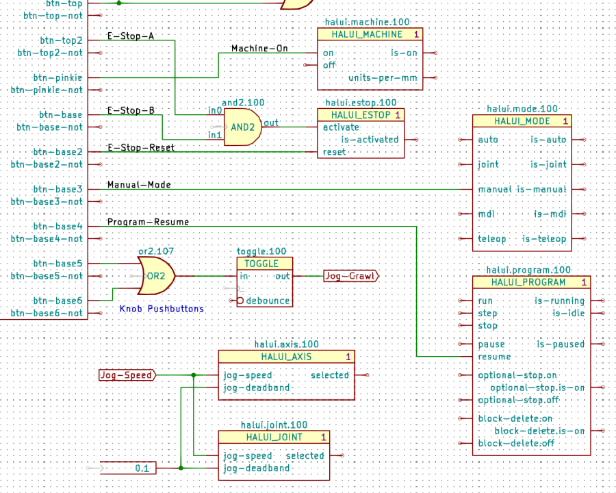
The Kicad references (halui.mode.100) use periods as separators, not dashes, because HALUI runs automagically and has no thread functions.
The symbol name (HALUI_MODE) serves as a unique identifier that should match the reference stem. I used underscores just for pretty, but it doesn’t make any difference.
All of the Kicad symbols include the StripAnno field to remove the Kicad annotation, as described earlier. The Kicad annotations now start from 100, because I’m in the midst of tinkering an automagic way to produce the proper start-from-zero HAL numbering with everything properly sorted; this is very much a work in progress.
So the full name of the resume pin on the HALUI_PROGRAM component sporting Kicad reference halui.program.100 is just:
halui.program.resume
This corresponds to the description of that pin in the HALUI doc, without a numeric identifier: there is only one HALUI.
The net connecting the gamepad button to that pin:
net _Gamepad_Buttons_Program-Resume <= input.0.btn-base4 => halui.program.resume
A few more examples from the nets near the AND2 gate:
net _Gamepad_Buttons_E-Stop-A <= input.0.btn-top2 => and2.0.in0
net _Gamepad_Buttons_E-Stop-B <= input.0.btn-base => and2.0.in1
net _Gamepad_Buttons_E-Stop-Reset <= input.0.btn-base2 => halui.estop.reset
net _Gamepad_Buttons_Machine-On <= input.0.btn-pinkie => halui.machine.on
net _Gamepad_Buttons_Manual-Mode <= input.0.btn-base3 => halui.mode.manual
Some HALUI component references include numbers and letters identifying specific joints / axes / spindles, all of which you must edit as needed and none of which should be subjected to Kicad’s renumbering whims:
X Axis jogging schematic
The HAL commands producing the nets connecting the AND2 gates to the HALUI pins:
net N_065 <= and2.14.out => halui.axis.x.minus halui.joint.0.minus
net N_066 <= and2.15.out => halui.axis.x.plus halui.joint.0.plus
The nets lack any specific name, so Kicad-to-HAL replaces Kicad’s default gibberish with the next integer from an ascending series. If your HAL configuration requires more than three digits worth of anonymous nets, feel free to tweak the format string.
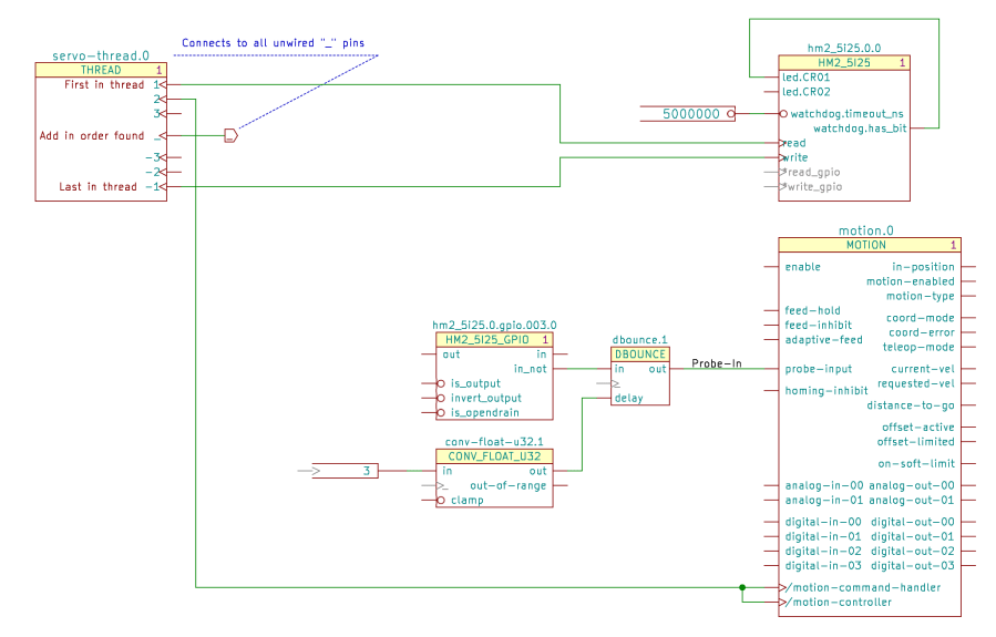
Kicad insists on annotating every component with a numeric suffix that can change depending on the sequence of components encountered during the annotation process. HAL, on the other hand, identifies multiple components using a numeric value as a suffix or embedded within the reference. HAL also has singleton components without a numeric value.
A Moby Hack™ merges the two systems: Kicad will annotate each of its components, then Kicad-to-HAL can strip the annotation from the reference to form the HAL identifier.
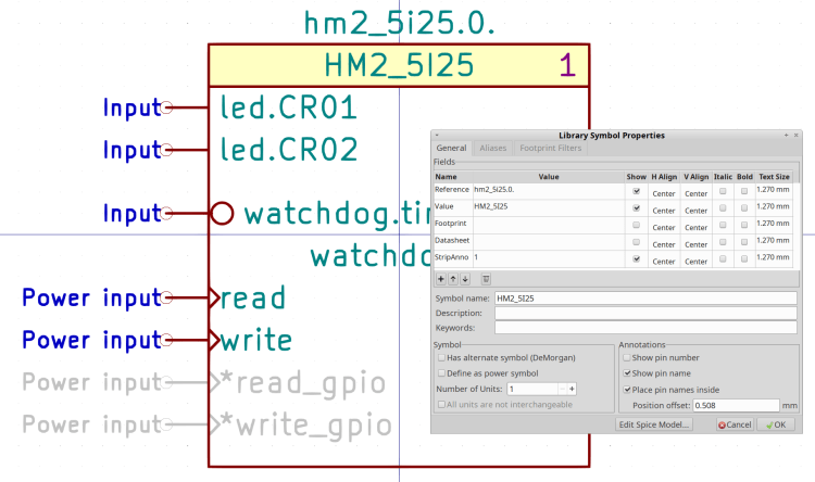
A Kicad component with a StripAnno field containing a “1” will trigger the stripping:
Kicad Symbol Properties – HM2_5I25
The StripAnno digit (generally) appears to the right of the component name. A Kicad component without a StripAnno field or with the field containing anything other than “1” will pass its reference field directly into the HAL component.
The Kicad reference for the HM2_5I25 component (center right) is hm2_5i25.0.0 and its stripped HAL reference is hm2_5i25.0:
addf hm2_5i25.0.read servo-thread
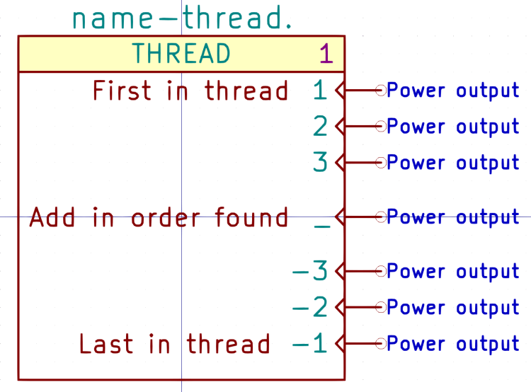
The THREAD component (center bottom) is a singleton, because there will be only one component with a given thread name:
Kicad symbol – THREAD
The Kicad reference appends a zero to make servo-thread.0:
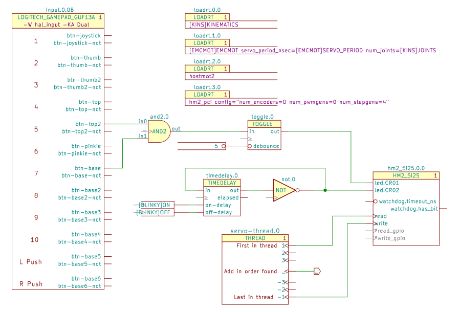
Kicad-to-HAL Demo Schematic
The stripped HAL reference, as used in addf statements, is just servo-thread:
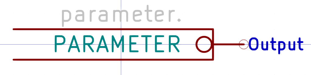
Kicad PARAMETER symbols (center, left of the upper TOGGLE) provide the value for HAL setp commands:
Kicad-to-HAL Demo Schematic
Which becomes this line in the HAL file:
setp toggle.0.debounce 5 # parameter.0
Parameter pins use the Inverted graphic style decorating them with a small circle to distinguish parameters from ordinary data pins, but the data value is not inverted. Parameter components can also connect to ordinary HAL input pins without the Inverted style.
PARAMETER symbols have an invisible reference value (parameter.0 in the example) that you don’t care about:
Kicad symbol – PARAMETER
Edit the value inside the symbol to whatever you need.
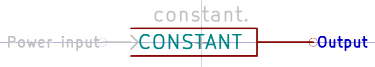
Kicad CONSTANT symbols (lower center, left of the TIMEDELAY symbol) generate HAL CONSTANT modules, set their values, and connect them to a thread. The resulting HAL commands look like this:
The (invisible) + in the middle tells Kicad-to-HAL to put the total number of CONSTANT components into the addf command.
As with Parameters, edit the CONSTANT inside the symbol as needed.
Both Parameters and Constants can use text values defined in the INI file:
[BLINKY]
ON = 0.2
OFF = 2.0
Both Parameters and Constants can connect to nets going to multiple input pins, but it’s probably not worth cluttering a schematic with off-page connectors just to reuse a single instance. When you copy-n-paste an otherwise identical symbol somewhere else, it will get a different reference number and generate additional HAL commands, which may offend your sense of neatness.
The Kicad THREAD symbol (center bottom) creates the HAL addf commands connecting HAL component functions to the realtime threads:
Kicad-to-HAL Demo Schematic
Change the Kicad reference to match the HAL thread name. AFAICT, you can use either servo-thread or base-thread, as defined by the LoadRT configuration (center top).
Opinion: contemporary x86-64 PC architecture pretty much prevents running a base-thread at the pace required for step generation through a parallel port. In point of fact, I wrote Kicad-to-HAL specifically to configure a PC around a Mesa Electronics 5i25 FPGA controller for my Sherline CNC mill, as the real-time latency had regular glitches far exceeding the nominal 50 µs period. I suspect few new CNC installations will need a fast base thread.
The THREAD symbol has seven “Power output” pins drawn in the Clock graphic style:
Kicad symbol – THREAD
Kicad-to-HAL finds the other components attached to each pin and generates addf commands:
FiXME: Contrary to the comment in the symbol, addf commands for each pin come out sorted by reference.
The Mesa hostmot2 HAL component (middle right in the first screenshot) generates several function names that don’t require connections, but Kicad-to-HAL produces a warning for single-pin (i.e. unconnected) nets with non-default names. Prefix the pin name with an asterisk (*read-gpio) to suppress the error message.
The motion HAL component (lower right below) has functions that do not follow the normal naming convention:
Servo Thread Hookup schematic
Prefix the Kicad pin name with a slash (/motion-controller) to tell Kicad-to-HAL to use the name without the standard motion. prefix:
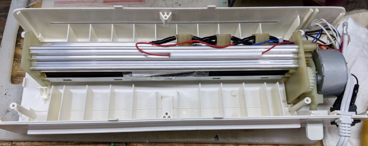
My AmazonBasics laminator wrapped a small card around one of its rollers and jammed solid:
AmazonBasics laminator – interior bottom
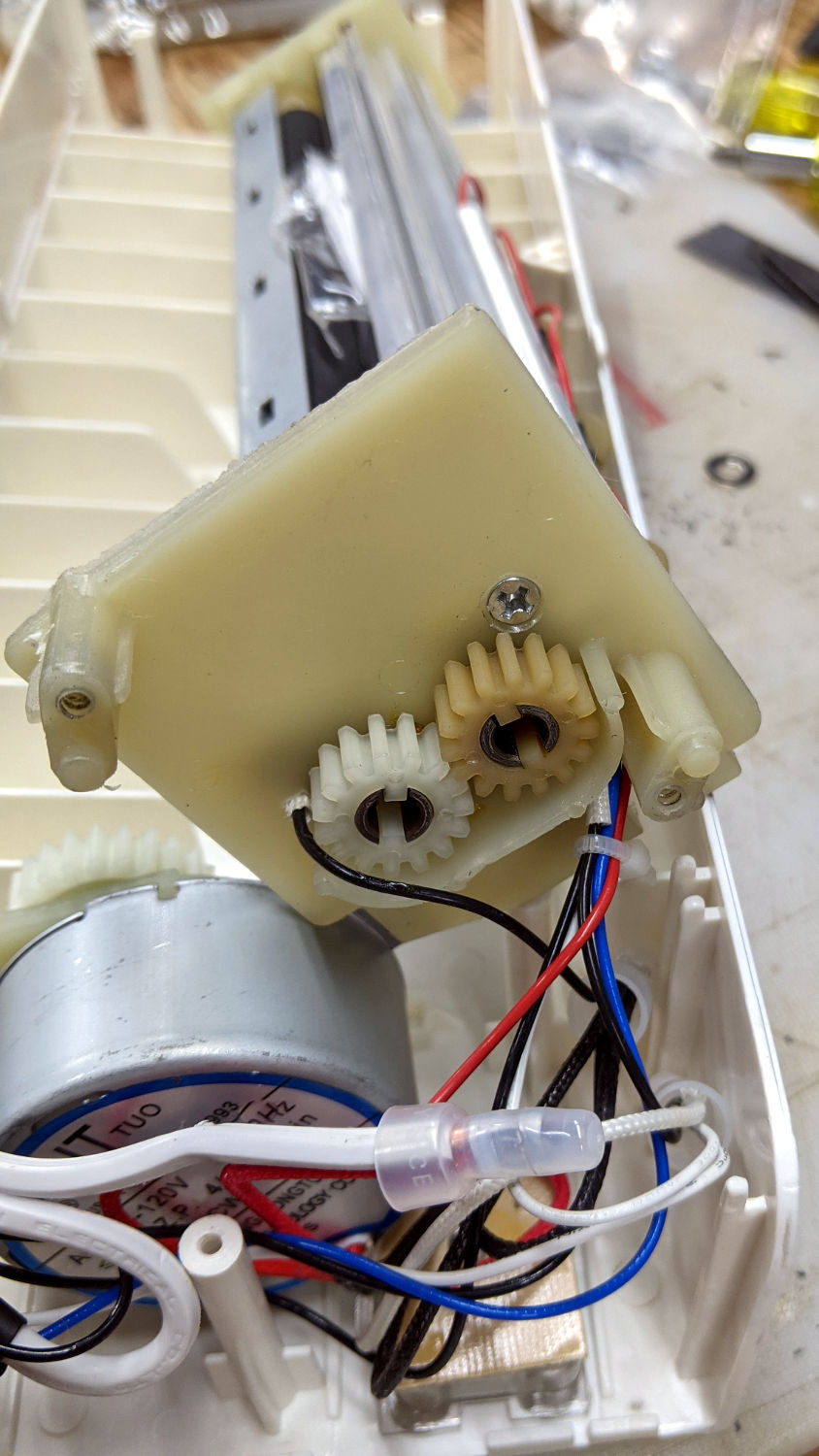
The lever sticking out on the lower right (above) drives the rollers in reverse by moving the motor from one gear to the other:
AmazonBasics laminator – roller gears
Obviously, reverse gear wouldn’t get me anywhere, but dismantling the rollers required cutting the junction between the heating elements running through the aluminum extrusions:
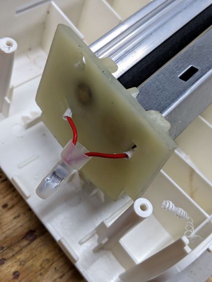
AmazonBasics laminator – heater junction
I spliced a few inches of wire onto those leads. If there’s a next time, I can cut the splice in the middle and use a wire nut.
The white plastic curl in the lower right showed they ran a deburring tool around the exit slot and called it Good Enough™.
The gears slide off the roller shafts and the rollers out of the extrusions, after which removing the tightly wrapped and completely useless card posed no problem.
One lone, short, and eagerly self-tapping screw holds each plastic end plate to the extrusion, so be careful about cross-threading.
All in all, this was easy enough, although I’m sure I was supposed to just throw the laminator away and buy a new one.