Ed Nisley's Blog: Shop notes, electronics, firmware, machinery, 3D printing, laser cuttery, and curiosities. Contents: 100% human thinking, 0% AI slop.
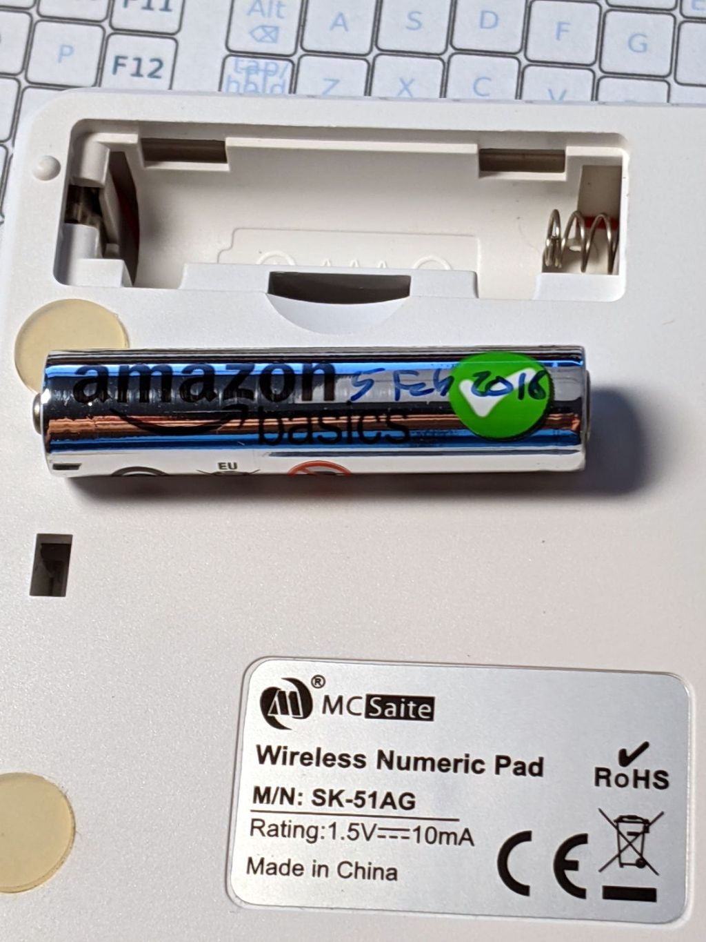
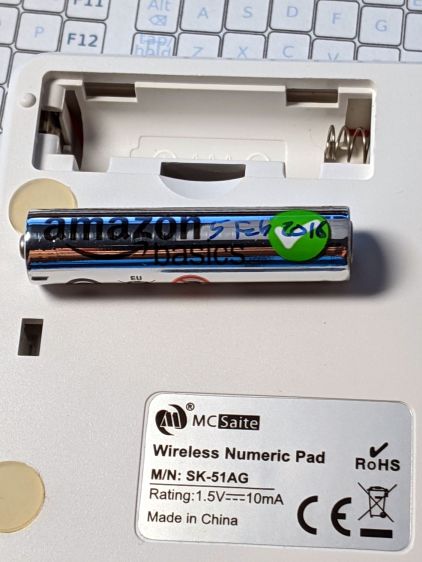
One of the streaming media players behaved funny, which always results in a numeric keypad battery replacement. This AmazonBasics AAA alkaline was down to about 0.5 V and long past its best-used-by date:
Suggestions that Amazon monitors their Marketplace sellers to figure out what’s profitable, then promote a Good Enough house brand product to kill off the competition, seem to describe the situation just about perfectly.
The CNC 3018 Z-axis stage has a plastic clamp holding the spindle motor, so I just duplicated the motor diameter in the mounts for my diamond drag bit, cheap pen, and fancy pen holders. For obvious reasons, I tend to err on the small side for anything intended to fit into anything else, which led to each of the holders sporting a small strip of tape to soak up the difference.
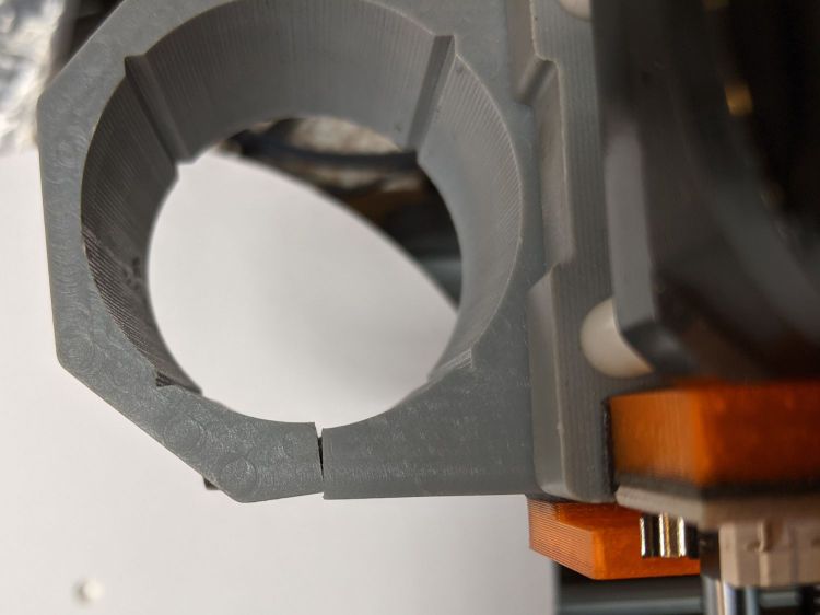
While poking around the 3018, I once again noticed the clamp’s crappy fit around the holder:
CNC3018 tool clamp – top
The inside should be circular, but it’s definitely not:
CNC3018 tool clamp – top detail
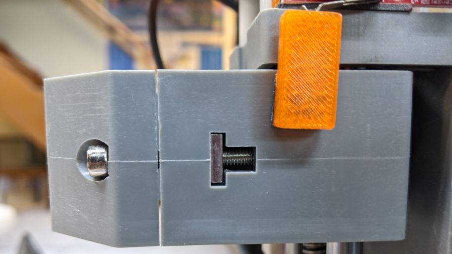
The end of the 30 mm M3 SHCS bottoms out before the clamp closes, although I’ve managed to crank the screw tight enough to put enough of a dent in there to snug the clamp:
CNC3018 tool clamp – side
Some awkward scraping and filing eroded enough of the plastic to let a 25 mm SHCS close the clamp firmly around the holder:
CNC3018 tool clamp – revised
The tool holders now slide in easily with the screw released and fit firmly with the screw tightened a reasonable amount, minus the tape snippets shimming the difference.
If I had the courage of my convictions, I’d take it all apart, bore the clamp out to a circular profile, realign the clamp screw passage to suit, then rebuild all those tool holders for the new diameter; it now works well enough to tamp that project down.
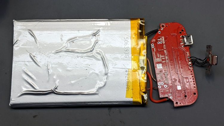
The iPhone was nowhere to be found, so harvesting its organs seemed appropriate:
Alpatronix iPhone XS case – opened
I assume the four steel disks aligned the coil with the wireless charger.
A few hours of steady tension relieved enough of the sticky tape to release the battery:
Alpatronix iPhone XS case – battery removal
Although its bag now sports a few wrinkles:
Alpatronix iPhone XS case – battery adhesion
The alert reader will note the outside of case proudly proclaimed “Capacity: 5000 mAh” while the underside of the battery says “4920 mAh”, but that’s surely close enough for consumer electronics these days.
The battery charges through either the Qi coil or a (mercifully standard Micro-B) USB jack and everything seems to work.
Not sure what I’ll do with a bare lithium cell and its charger, but they ought to come in handy for something around here.
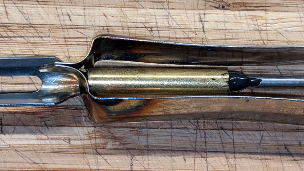
The blade on one of the Jonas vegetable peelers cracked, which suggests it’s the counterfeit version:
Jonas Peeler – cracked blade
I grooved the metal pin running through the handle:
Jonas Peeler – shaft grooving
A brass tube from the Little Tray o’ Cutoffs and some epoxy should hold things together forevermore:
Jonas Peeler – epoxy
The rainbow colors come from an instantly aborted attempt to silver-solder the parts together. The fact that I even tried a stunt like that shows I’m definitely not the brightest bulb in the chandelier these days.
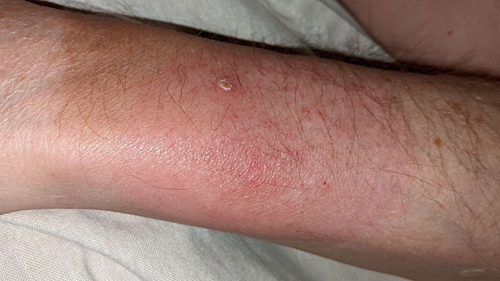
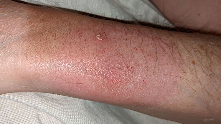
For reasons that made sense at the time, two weeks ago I ventured outside the house. A few days later, this appeared:
Lyme Disease – arm rash
The pallid skin over on the left comes from a bike glove. The central bump is one of those annoying sebaceous hyperplasias appearing after a Certain Age and not relevant here.
Having been around this particular block a few times, Mary recognized the diffuse red rash, sleeping 30 of 36 consecutive hours, and a day-long 103 °F fever as Lyme disease. I’m currently taking 100 mg of doxycycline twice a day and (after a week) feeling better, while sleeping a lot more than usual at random intervals during the day.
We’re both highly aware of Lyme disease: Mary routinely dresses in a complete overlayer of permethrin-sprayed clothing and I generally strip-and-shower immediately after any yard work in similarly sprayed, albeit less enclosing, attire. In this case, we think a tiny Deer Tick nymph affixed itself to the outboard side of my wrist, where I could neither see nor feel it, and (because I didn’t take a shower after being outside for only a few minutes) remained attached long enough to infect me.
Caught and treated early, Lyme disease generally does not progress into “post-treatment Lyme disease”, an ailment rife with what can charitably be described as serious woo, despite some evidence of actual disease.
Some of Mary’s Master Gardener cronies have endured co-infections of Babesia microti and we’ll be watching for those symptoms after doxycycline tamps down the obvious problem.
I’ll be puttering very carefully around heavy machinery and posting irregularly for a few weeks …
Memo to Self: the Basement Shop has a lot to recommend it!
For completeness, all of the surviving UPS sealed lead-acid batteries compared with a new battery:
UPS SLA 2021-10-22
They’re all discharged at 4 A, far higher than the nominal “20 hour” rate of 450 mA = 9 A·hr / 20 hr, but an order of magnitude closer to the rated UPS output of a few hundred watts which would call for a few tens of amps.
The new battery delivers 73 W·hr under those conditions, perhaps 50% more than the 50-ish W·hr from the used batteries, and with a much higher overall terminal voltage during the discharge.