A test setup on the bench allows a bit more room for probes:
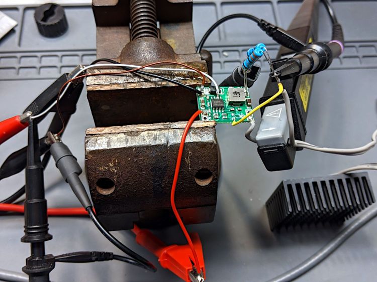
Some heatsink tape holds the LED to the far side of that oversize heatsink.
The input signal (top trace) arrives from a function generator set to blip the MP1584 regulator’s Enable input at 4 Hz with a 7 ms pulse:
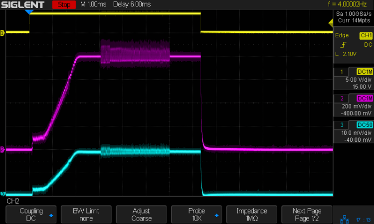
The purple trace is the voltage across the 2 Ω sense resistor. The MP1584 datasheet says the regulator soft-starts for (typically) 1.5 ms, during which the output ramps upward at 600 mV/ms to 800 mV , whereupon the actual regulation commences. The amber LED forward drop adds 2.5 V to the sense voltage, so the regulator produces 3.3 V from the 6.3 V bench supply input.
The cyan trace is the output current through the LED and sense resistor, also ramping up to 800 mV/2 Ω = 400 mA to drive the LED at 1 W.
The furry section shows when the regulator is actively regulating, with the output voltage rising and falling over a small range to maintain the average current (via the sense voltage). Successive Enable pulses may have longer, shorter, or completely missing fur, with no predictable pattern. Increasing the duty cycle doesn’t affect the results, with the fur sometimes extending for the entire pulse and sometimes being completely missing.
I think the regulator can settle in one of two metastable states. The best case has a constant voltage producing a constant LED current, with the sense voltage remaining within whatever deadband keeps the error amplifier happy. When something knocks the sense voltage out of the deadband, the error amp starts the usual regulation cycle, which will stop when the minimum or maximum voltage of a cycle remains within the deadband:
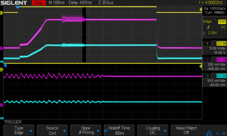
The ripple shows the regulator running at three cycles per 20 µs division = 150 kHz, far lower then the MP1584 datasheet’s maximum 1.5 MHz and the typical 500 kHz in the test circuits. Perhaps a low frequency lets the designers use a cheap PCB and not worry about pesky EMI issues.
In any event, during this pulse the ripple amplitude gradually decreased as the output voltage settled at the point where the error voltage variation stayed within the deadband. The typical amp gain is only 200 V/V, so it’s definitely less fussy than something build around an op amp.
For whatever it’s worth, a 7 ms flash from a 1 W amber LED at 4 Hz is way attention-getting in a dim Basement Laboratory. You wouldn’t need an Arduino to produce that signal, even though I like the Morse capability.
