Ed Nisley's Blog: Shop notes, electronics, firmware, machinery, 3D printing, laser cuttery, and curiosities. Contents: 100% human thinking, 0% AI slop.
The UPS coddling the M2 printer began complaining about a bad battery, so I ran (nearly) all the UPS batteries through the tester:
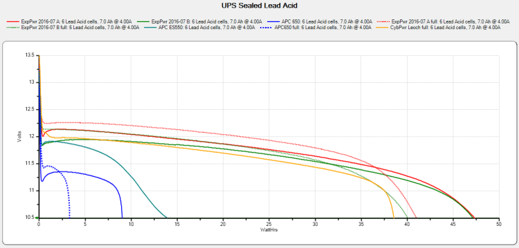
UPS SLA 2021-10-10
The two blue flubs in the lower left come from the failed battery, with the dotted trace after charging to 13.7 V and letting the current drop to 20 mA.
The red and green traces come from two other UPS batteries installed in 2016, with the dotted traces after charging similarly. The orange-ish trace is from the battery in a Cyberpower UPS bought in 2016, so it looks like all batteries of that vintage fade equally.
Except for another pair of batteries in another UPS that had discharged stone cold dead; it may have been shut down and unplugged during a power outage and they never quite recovered.
After five years, it’s time to refresh the fleet …
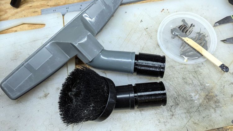
Because the tubes get epoxied into the adapters, there’s no particular need for a smooth surface finish and, in fact, some surface roughness makes for a good epoxy bond. The interior of a 3D printed adapter is nothing if not rough; the epoxy in between will be perfectly happy.
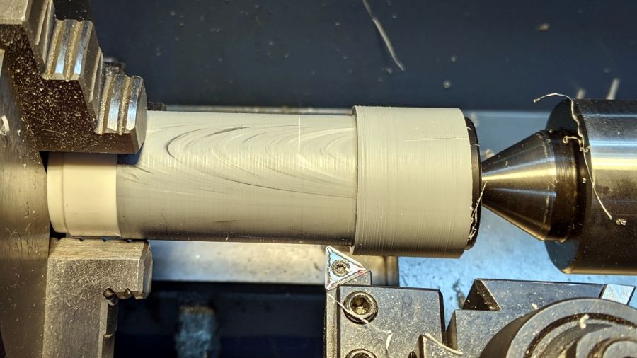
Turning the tubes started by just grabbing the conduit in the chuck and peeling the end that stuck out down to the finished diameter, because the conduit was thick-walled enough to let that work.
The remaining wall was so thin that the chuck would crunch it into a three-lobed shape, so the white ring in the chuck is a scrap of PVC pipe turned to fit the tube ID and provide enough reinforcement to keep the tube round.
The conduit ID isn’t a controlled dimension and was, in point of fact, not particularly round. It was, however, smooth, which counts for more than anything inside a tube carrying airborne fuzzy debris; polishing the interior of a lathe-bored pipe simply wasn’t going to happen.
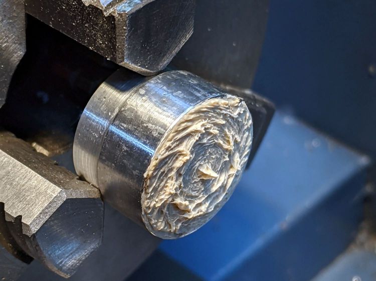
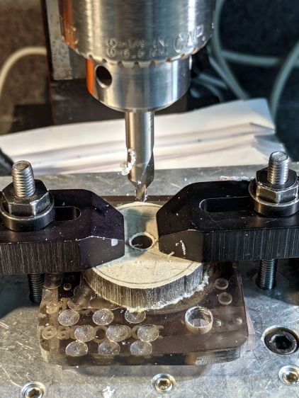
The fixture on the other end started as a scrap of polycarbonate bandsawed into a disk with a hole center-drilled in the middle:
Pipe end lathe fixture – center drilling
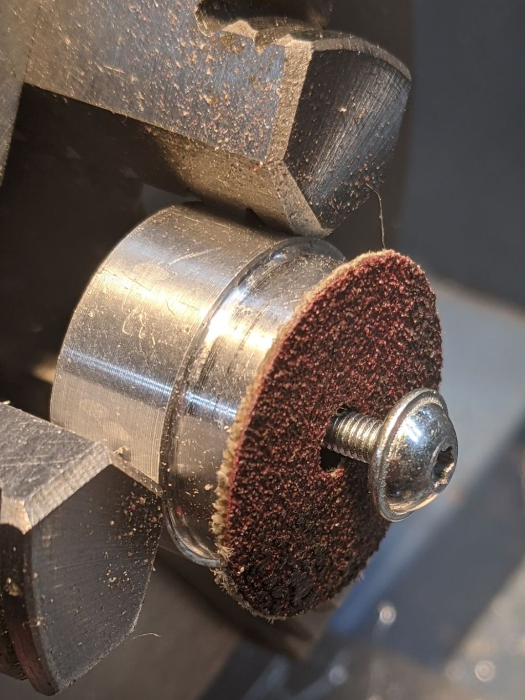
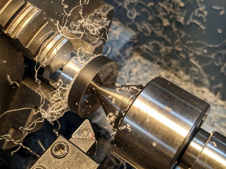
Stick it onto a disk turning fixture and sissy-cut the OD down a little smaller than the eventual tube OD:
Pipe end lathe fixture – turning OD
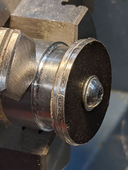
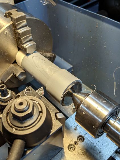
Turn the end down to fit the tube ID, flip it around to center-drill the other side, stick it into the tube, and finally finish the job:
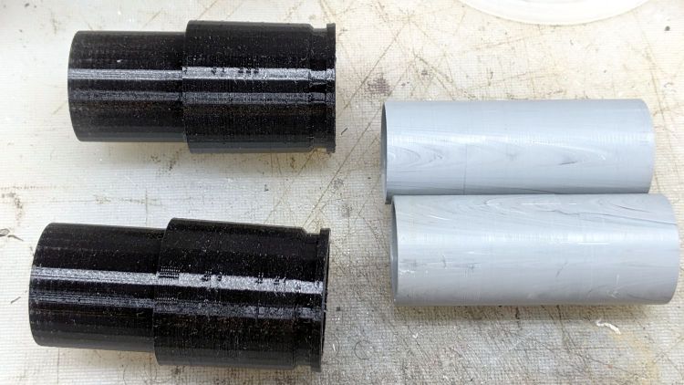
Dirt Devil adapter – pipe fixture
The nice layering effect along the tube probably comes from molding the conduit from recycled PVC with no particular concern for color matching.
A family portrait of the fixtures with a finished adapter:
Dirt Devil adapter – fixtures
A fine chunk of Quality Shop Time: solid modeling, 3D printing, mini-lathe turning, and even some coordinate drilling on the Sherline.
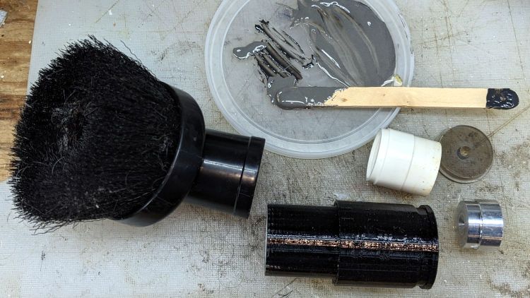
A smear of epoxy around the interior holds the tube in place:
Dirt Devil adapters – assembled
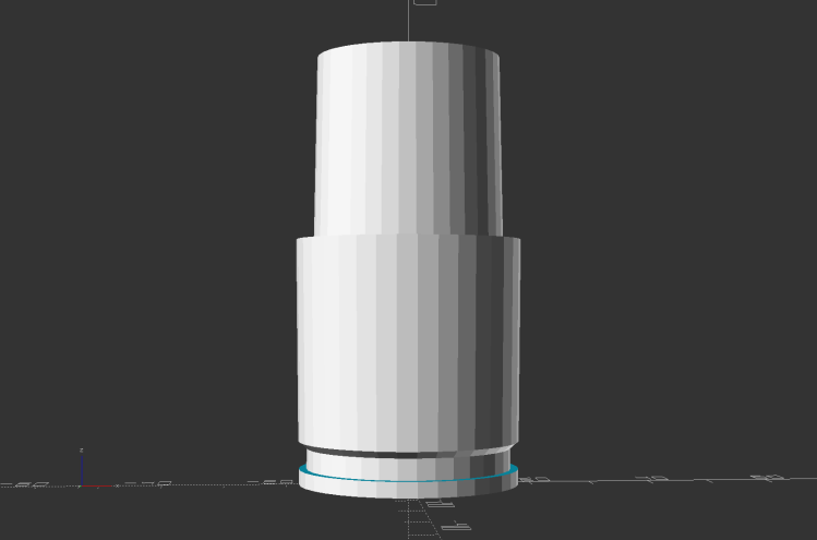
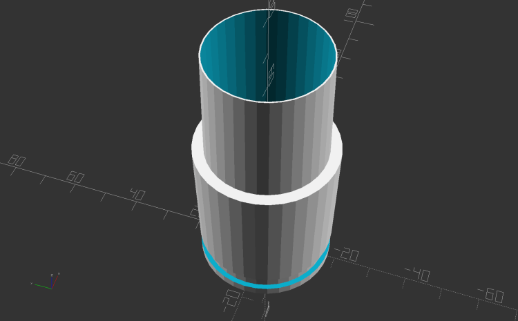
Building the critical dimensions with a 3D printed part simplified the project, because I could (and did!) tweak the OpenSCAD code to match the tapers to the tools. Turning four of those tubes from a chunk of PVC conduit, however, makes a story for another day.
This file contains hidden or bidirectional Unicode text that may be interpreted or compiled differently than what appears below. To review, open the file in an editor that reveals hidden Unicode characters.
Learn more about bidirectional Unicode characters
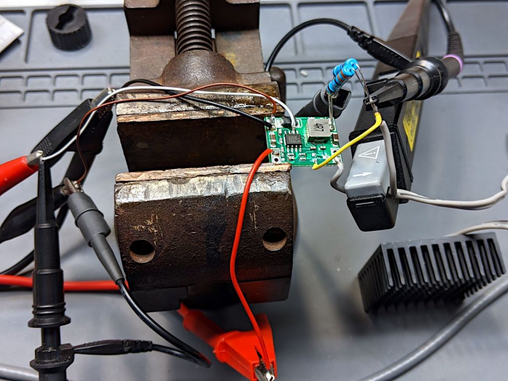
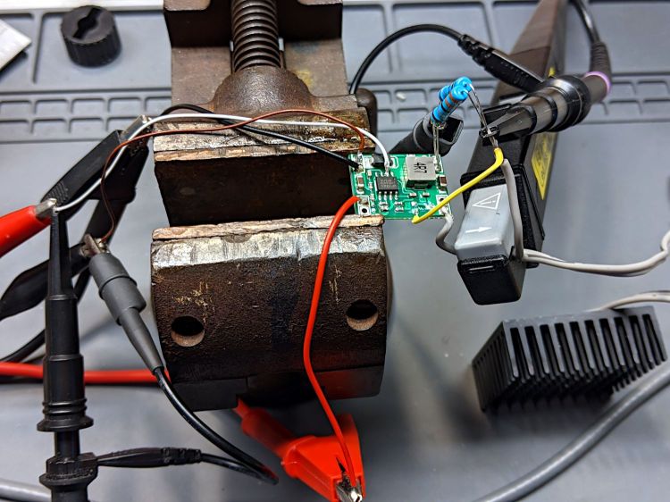
A test setup on the bench allows a bit more room for probes:
1 W Amber LED – MP1584 pulse setup
Some heatsink tape holds the LED to the far side of that oversize heatsink.
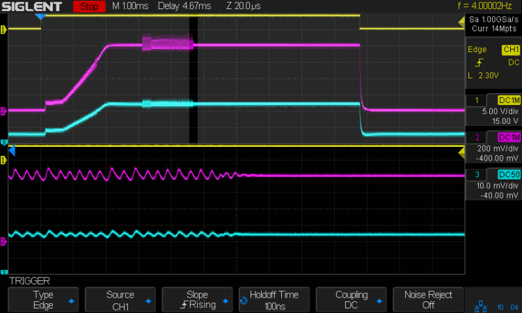
The input signal (top trace) arrives from a function generator set to blip the MP1584 regulator’s Enable input at 4 Hz with a 7 ms pulse:
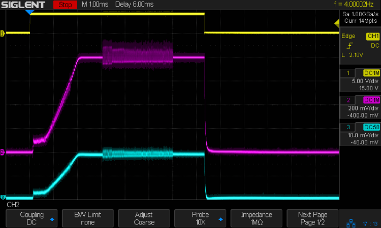
Amber 1 w LED – pulse 200 mA-div
The purple trace is the voltage across the 2 Ω sense resistor. The MP1584 datasheet says the regulator soft-starts for (typically) 1.5 ms, during which the output ramps upward at 600 mV/ms to 800 mV , whereupon the actual regulation commences. The amber LED forward drop adds 2.5 V to the sense voltage, so the regulator produces 3.3 V from the 6.3 V bench supply input.
The cyan trace is the output current through the LED and sense resistor, also ramping up to 800 mV/2 Ω = 400 mA to drive the LED at 1 W.
The furry section shows when the regulator is actively regulating, with the output voltage rising and falling over a small range to maintain the average current (via the sense voltage). Successive Enable pulses may have longer, shorter, or completely missing fur, with no predictable pattern. Increasing the duty cycle doesn’t affect the results, with the fur sometimes extending for the entire pulse and sometimes being completely missing.
I think the regulator can settle in one of two metastable states. The best case has a constant voltage producing a constant LED current, with the sense voltage remaining within whatever deadband keeps the error amplifier happy. When something knocks the sense voltage out of the deadband, the error amp starts the usual regulation cycle, which will stop when the minimum or maximum voltage of a cycle remains within the deadband:
Amber 1 w LED – pulse – detail – 200 mA-div
The ripple shows the regulator running at three cycles per 20 µs division = 150 kHz, far lower then the MP1584 datasheet’s maximum 1.5 MHz and the typical 500 kHz in the test circuits. Perhaps a low frequency lets the designers use a cheap PCB and not worry about pesky EMI issues.
In any event, during this pulse the ripple amplitude gradually decreased as the output voltage settled at the point where the error voltage variation stayed within the deadband. The typical amp gain is only 200 V/V, so it’s definitely less fussy than something build around an op amp.
For whatever it’s worth, a 7 ms flash from a 1 W amber LED at 4 Hz is way attention-getting in a dim Basement Laboratory. You wouldn’t need an Arduino to produce that signal, even though I like the Morse capability.
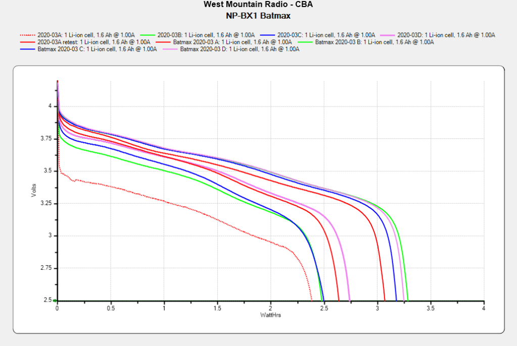
The Sony HDR-AX30V helmet camera puts far more demands on its battery than the Planet Bike Superflash:
Batmax NP-BX1 – 2021-09 vs 2020-03
The four traces on the right show the BatMax NP-BX1 lithium batteries (cells, really) originally stored about 3 W·h when they arrived in March 2020. The four solid traces to their left show the capacity dropped to a little over 2 W·h after two riding seasons. Batteries B and C started out above average and are now below, for whatever that means.
The red dotted trace shows the effect of not using the NP-BX1 test holder for that length of time; those homebrew contact pins apparently needed some exercise.