Ed Nisley's Blog: Shop notes, electronics, firmware, machinery, 3D printing, laser cuttery, and curiosities. Contents: 100% human thinking, 0% AI slop.
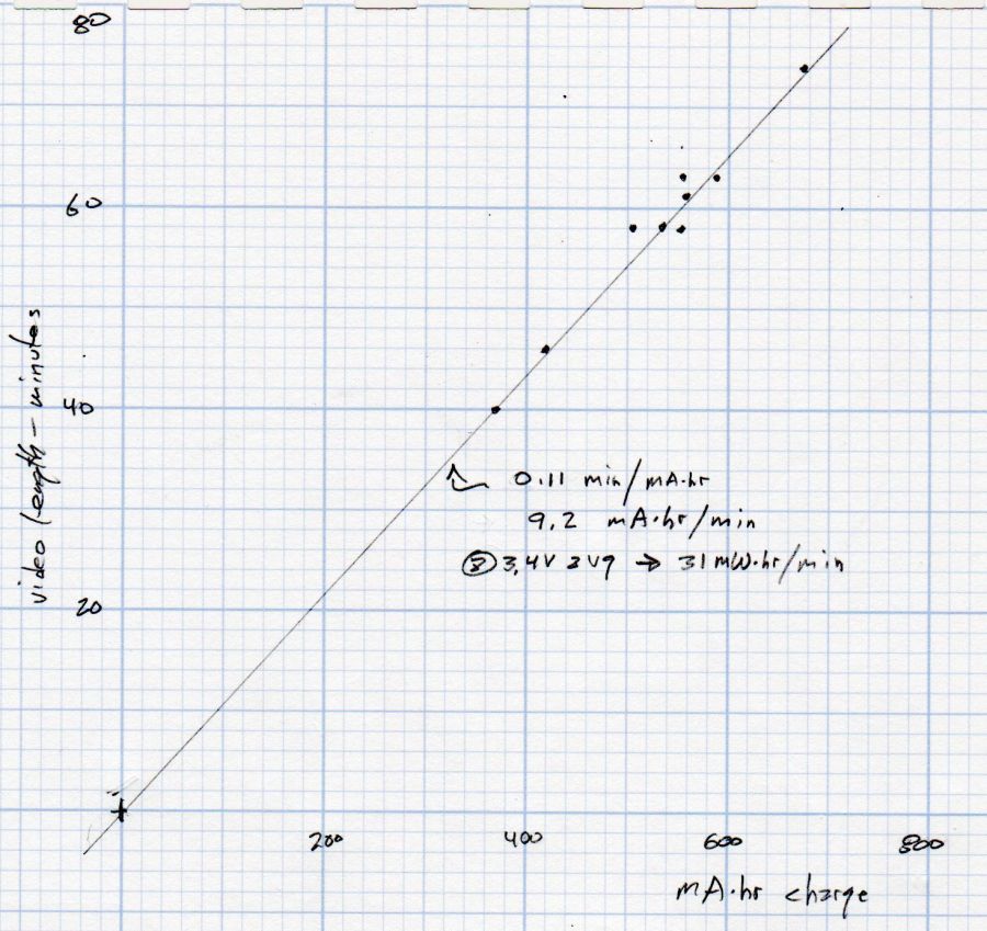
Having run the Newmowa NP-BX1 batteries through my old Sony HDR-AS30V helmet camera a few times, a plot seemed in order:
Newmowa NP-BX1 video duration vs charge
The cluster of dots shows most of our rides last about an hour.
The line is an eyeballometrical fit, slightly coerced to pass through the origin because that’s where it should go.
The 9.1 mA·hr/min slope is in reasonable agreement with past results, given different batteries and charger. The Keweisi meter emerged first from the box.
Straining the hr/min dimensional nonsense out of the slope suggests the camera averages 550 mA and 1.9 W. Derating those by a few percent to account for the recharge efficiency might be in order, but they’re surely in the right ballpark.
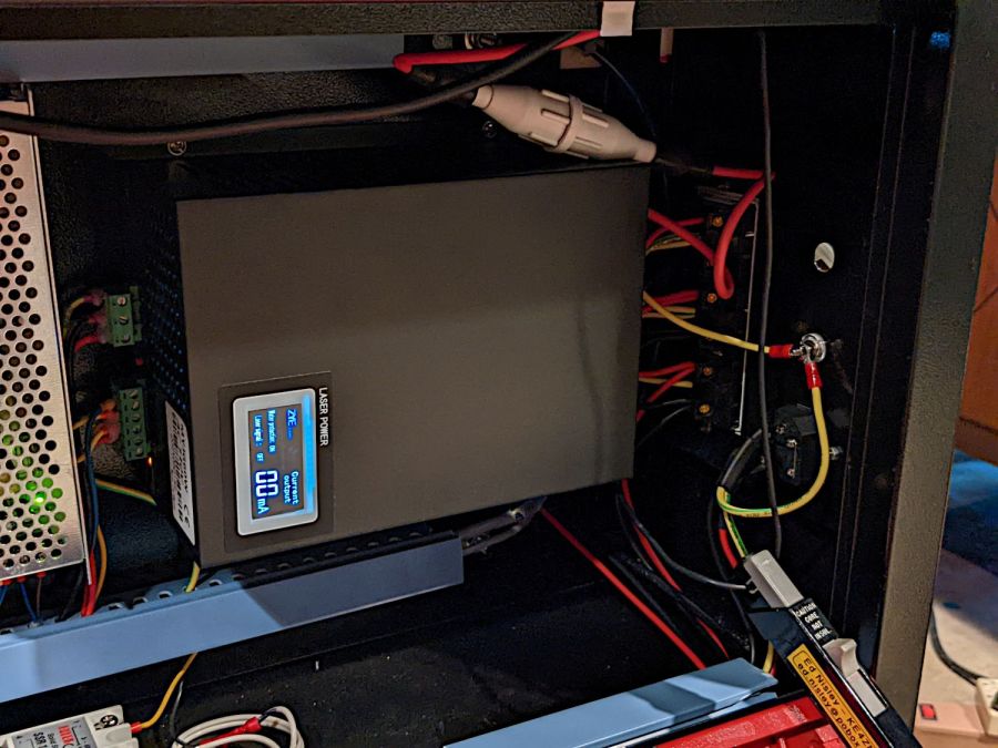
While I had the hatch open, I thought it would be interesting to look at the HV supply’s current waveforms:
HV laser power supply – current probe setup
The Tek current probe over on the right measures return current through the cathode wire, the point in the circuit where you might be tempted to install an ordinary analog (moving-coil) panel milliammeter, oriented so (conventional) current returning from the tube will produce a positive voltage.
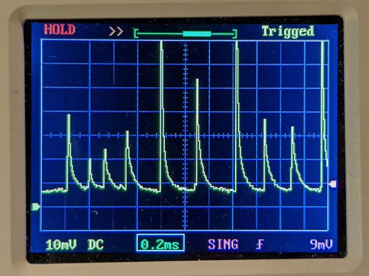
Unfortunately, an analog meter isn’t up to displaying anything meaningful for this nonsense:
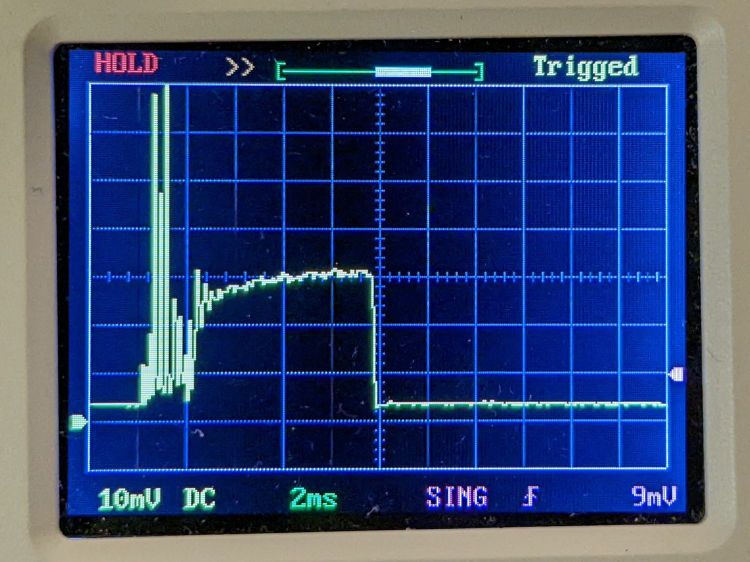
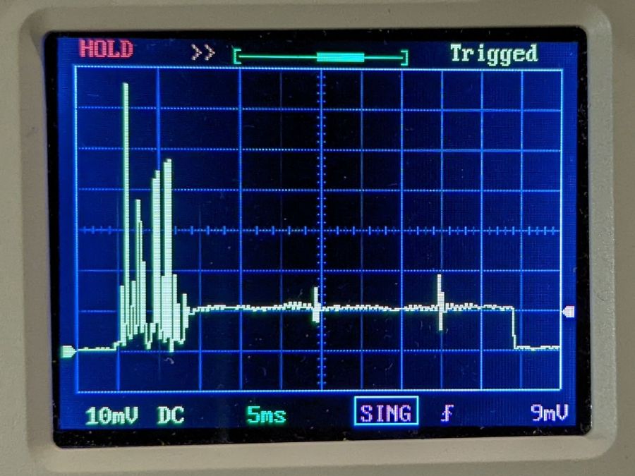
HV laser power supply – 5 mA-div – 50 ms 10 pct pulse
Admittedly, that’s a 50 ms pulse, during which an analog meter would barely twitch. The vertical scale is 5 mA/div, so the highest peaks exceed 35 mA, more than twice the tube’s recommended “14-15 mA”.
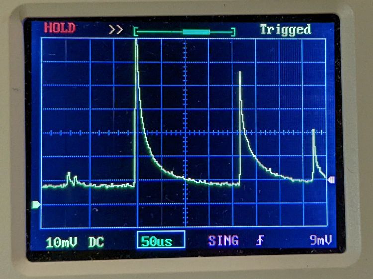
A closer look at the pulse startup waveform:
HV laser power supply – 5 mA-div – 50 ms 10 pct pulse – detail
HV laser power supply – 5 mA-div – 50 ms 10 pct pulse – tight detail
That’s at 10% PWM, close to the threshold below which the laser just won’t fire at all. The power supply must ramp up to produce enough voltage to fire the tube while simultaneously limiting the current to prevent the discharge from sliding down the negative resistance part of its curve.
Apparently this supply isn’t quite up to the task.
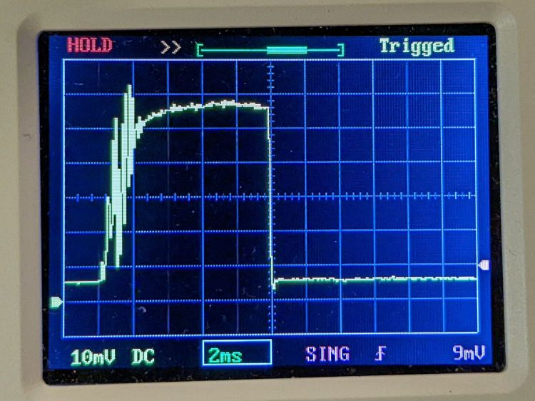
A 10 ms pulse at 50% PWM gives the supply enough time to stabilize the current:
HV laser power supply – 5 mA-div – 10 ms 50 pct pulse
The 14-ish mA at the tail end of the pulse (note the baseline offset) matches my previous 13 to 14 mA measurements as closely as seems reasonable. That 2 ms of hash on the leading edge suggests the start of each cut or engraving line will be a bit darker than you might expect.
Another 10 ms pulse, this time at 99% PWM:
HV laser power supply – 5 mA-div – 10 ms 99 pct pulse
The peak 24-ish mA matches the previous measurements. Note that the peaks in all the previous pictures exceed the 99% PWM current level.
AFAICT, all PWM values below about 25% produce equivalent results: random current spikes with unpredictable timing and amplitude. Changing the PWM value does not affect the (average) tube current or laser output power in any predictable way.
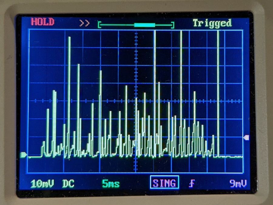
Some samples to illustrate the point, starting with a different 50 ms pulse at 10% PWM than the first one up above:
HV laser power supply – 5 mA-div – 50 ms 10 pct
A 50 ms pulse at 15% PWM:
HV laser power supply – 5 mA-div – 50 ms 15 pct
A 50 ms pulse at 20% PWM:
HV laser power supply – 5 mA-div – 50 ms 20 pct
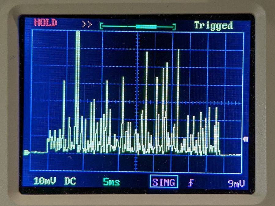
A 50 ms pulse at 25% PWM:
HV laser power supply – 5 mA-div – 50 ms 25 pct
Now, that last one is different. After the hash during the first 8 ms or so, the power supply actually produces a stable 5 mA beam current, which is roughly what I measured using the power supply’s meter.
However, the other three are pretty much identical: the 10% PWM pulse does not delivers half as energy as the 20% PWM pulse. The waveforms may be different, but not in a meaningful or consistent way: the two 50 ms 10% pulses are different, but you’d (well, I’d) have trouble separating them from the 20% pulse.
To summarize:
The first several millisconds of any pulse will consist of randomly distributed spikes with very large tube currents.
For PWM values greater than 25%, the tube current will settle down to the corresponding current after 5 to 10 ms. Before the current settles down, the tube will be firing those random spikes.
For PWM values less than 25%, the tube current never settles down: the entire pulse, no matter how long, will be short, high-intensity spikes, without a consistent DC-ish level.
No matter what an analog meter might show.
I have no way to know if this power supply is defective, but I’ll certainly ask …
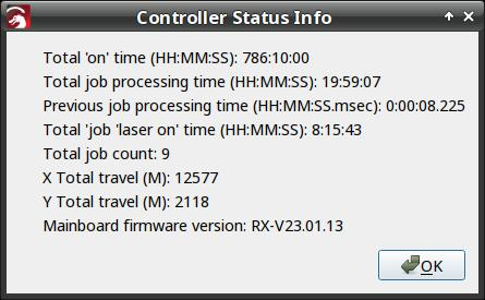
I think the Total job laser on time line says the power supply failed after firing the laser for a little over eight hours. The OMTech manual says the laser tube should last 1000 to 2000 hours (low vs high power), which suggests I should stock up on power supplies.
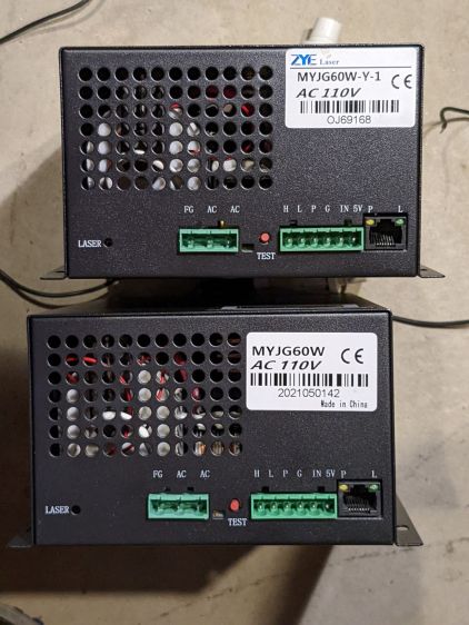
Its replacement just arrived:
OMTech replacement HV supply
It (bottom) seems to be a knockoff of the original ZYE Laser supply (top), with a similar model number and a “serial number” resembling a date from last year. All the connectors matched up, which isn’t too surprising.
The three most interesting inputs:
L = controller’s active-low L-ON enable output
IN = controller’s PWM output
P = jumper to G (circuit ground) — not water flow sensor
Also note the two AC power-line terminals directly adjacent to the TEST button, then consider insulation and stand-off distances before poking the button with your index finger.
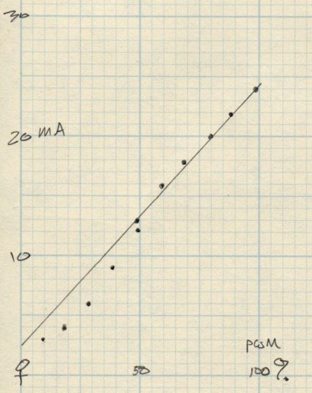
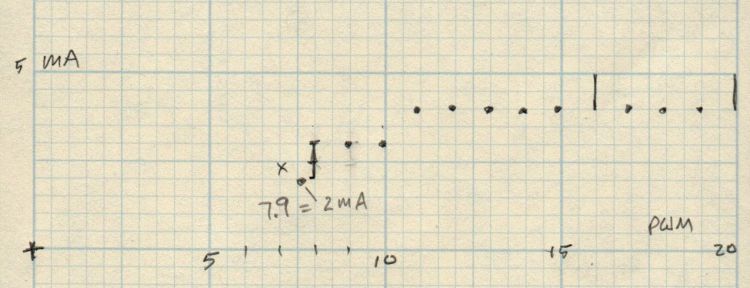
The power supply has a digital current meter, so I plotted output current against PWM input:
Laser Power Supply – mA vs PWM – overview
Taking more points at the low end, with vertical bars indicating single-digit flicker on the meter:
Laser Power Supply – mA vs PWM – 0 to 20 PWM
I have little reason to believe the meter reading indicates the true current with any accuracy and I know CO₂ laser output power does not scale linearly with the current.
But it’s cutting again, which is a step in the right direction.
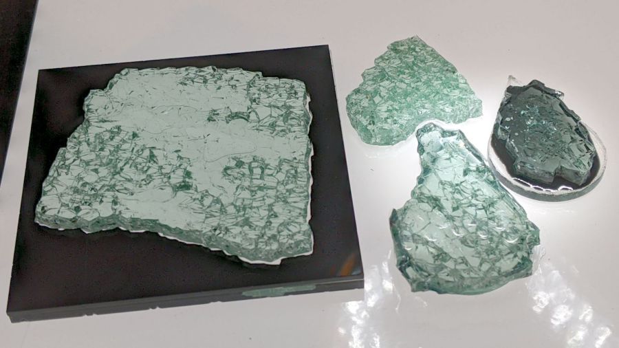
Just to see what happens, I laid some smashed glass in puddles of epoxy:
Smashed Glass vs epoxy – samples
Backlighting with the LED light pad reveals more detail:
Smashed Glass vs epoxy – backlit samples
The chunk on the left is the proof-of-concept shot glass coaster with a form-fit black acrylic mask atop a clear epoxy layer on a clear acrylic base. The chunk at the top is raw shattered glass fresh from the pile. The two chunks on teardrop acrylic scraps are bedded in transparent black and opaque black tinted epoxy.
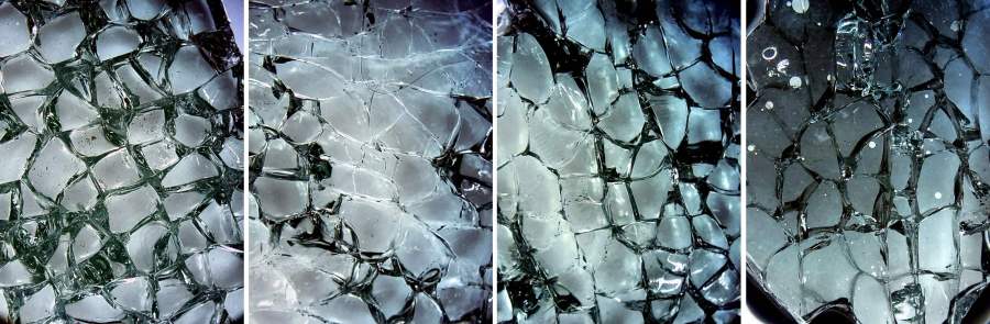
A look through the microscope at all four, laid out in that order, with the contrast blown out to emphasize the grain boundaries:
Smashed Glass vs epoxy – magnified comparison
You may want to open the image in a new tab for more detail.
The raw chunk has air between all its cuboids, so it’s nicely glittery. All the others have much of their air replaced by epoxy.
Clear epoxy produces an essentially transparent layer where it fills the gaps, because its refractive index comes close enough to the glass. The stretched contrast makes the gaps visible again, but the backlit image shows the unassisted eyeball view.
Transparent black dye sounds like an oxymoron, but it fills the gaps with enough contrast to remain visible. The overall chunk is not particularly glittery, but it’s OK.
Opaque black dye produces a much darker tint; the slightly tapered thin layer between the glass and acrylic (the small white circles are air bubbles) cuts down on the transmitted light. The gaps remain nearly as prominent as in the air-filled chunk, although with very little glitter.
Bedding the glass in epoxy against an acrylic sheet should reduce its tendency to fall apart at the slightest provocation, although the proof-of-concept poured coaster showed the epoxy must cover the entire edge of the glass sheet to bond all the slivers in place.
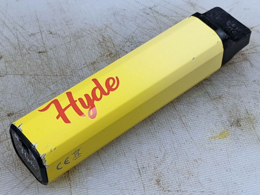
It’s a Hyde Edge Recharge vape pen or it could be a counterfeit. You (definitely not me) get “up to” 3300 puffs from the 10 ml container, with 50 mg of nicotine ensuring you can’t get enough and will come back for more. Although I don’t follow the market, “disposable” vape pens can still contain the fruity flavors prohibited in refillable pens, with the added decadence of throwing the whole thing away when the tank runs dry:
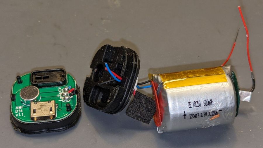
Hyde Charge Vape Pen – components
My admittedly inexperienced eye says the “tank”, which is really just a fiber cylinder soaked in fruity juice + nicotine, still has plenty of hits remaining.
The Basement Shop may never smell the same again.
Of more interest, the silvery lump wrapped in a white felt strip is a 600 mA·hr lithium cell that slurped 406 mA·hr through its USB Micro-B jack when I recharged it. Perhaps the uservictim sucker tossed it when the battery “died”, being unable / unwilling / ignorant-of-how to recharge it? The yellow aluminum case seems faded on the mouthpiece end, but that might be a stylin’ thing.
A closer look at the electronics payload:
Hyde Charge Vape Pen – electronics
The two red wires over on the right went to the coil in the draw tube to the right of the “tank”. Not being interested enough to care, I wrecked the coil while extracting the rest of the contents. Comfortingly, the red and black wires from the PCB go to the positive and negative battery tabs.
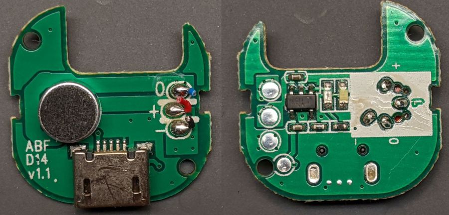
A closer look at both sides of the PCB:
Hyde Charge Vape Pen – PCB detail
The SOT23 IC sports an LTH7 topmark corresponding to an LTC4054-4.2 Standalone Charge Controller (Analog Devices absorbed Linear in 2017). The two LEDs to its right glow red during charge and white during each puff.
The black felt disk covers an anonymous pressure sensor activating the coil during each puff. With four pins, the sensor must be far more complex than just a switch, but nowadays puff sensing could require an entire ARM microcontroller.