Ed Nisley's Blog: Shop notes, electronics, firmware, machinery, 3D printing, laser cuttery, and curiosities. Contents: 100% human thinking, 0% AI slop.
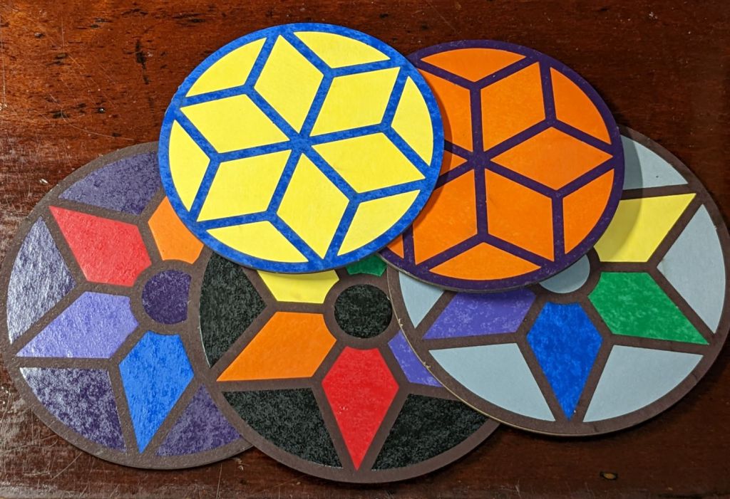
Cut the painted sheets cut face-down atop magnetic spikes on the honeycomb platform, with tabs to keep the petals in place and 0.15 mm kerf compensation. A light touch with an Xacto knife severs the tabs, after which the petals press firmly into the frames. Spread yellow PVA wood glue across the bottom disk, align the perimeters and press together, lay parchment paper between the coasters, clamp the stack between plywood sheets, and they emerge perfectly flat the next day.
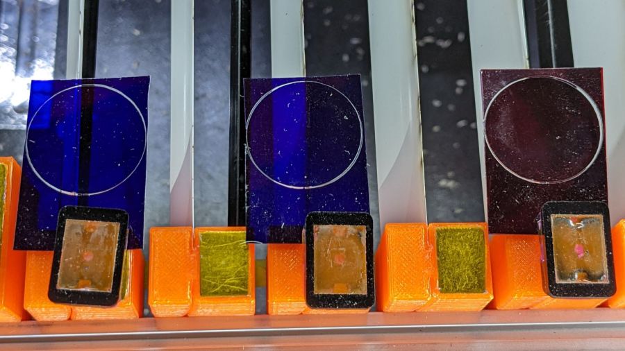
They’re too labor-intensive for any economic activity, but I like ’em:
Coaster assortment
The pale gray petals in a white frame looks remarkably like the washed-out color scheme on whatever device you’re reading this, doesn’t it?
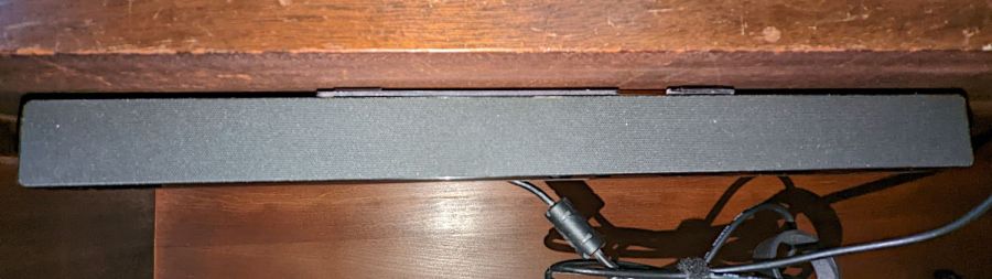
A bedroom rearrangement displaced the Dell Sound Bar attached to the streaming music player from its accustomed perch, so I conjured a mount from the parts bin to hang it from a shelf:
Dell sound bar mount – installed
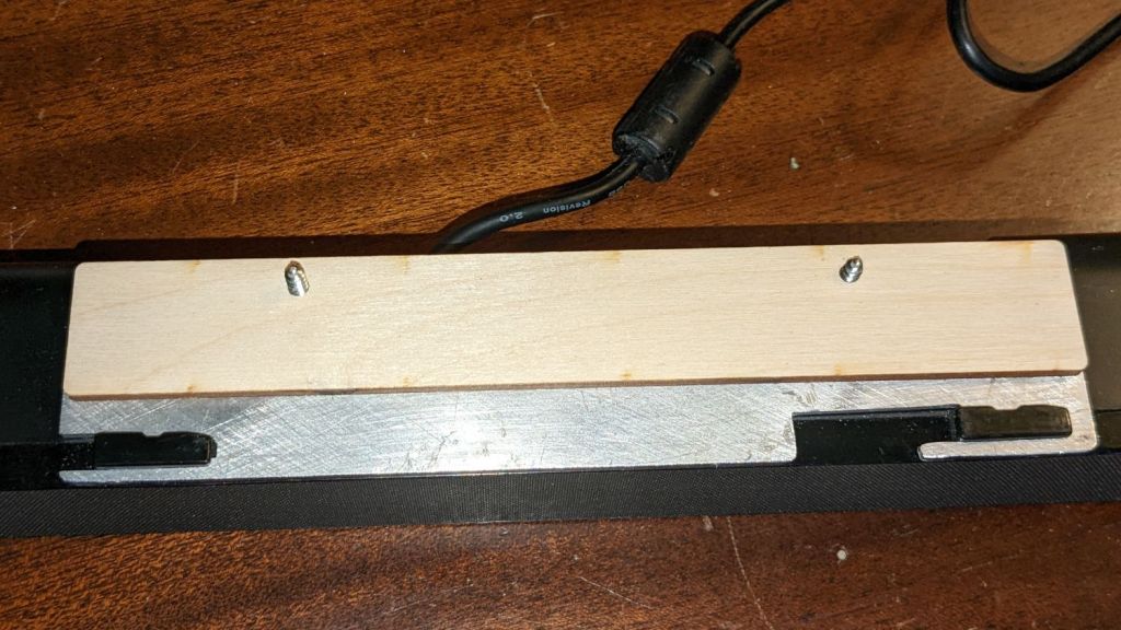
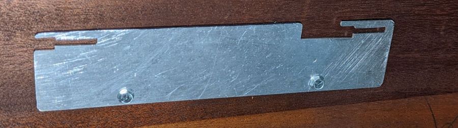
The sound bar originally fit below any Dell monitor with the appropriate lugs under the bezel, but a bit of bandsaw work and hand filing produced a reasonable facsimile from an aluminum sheet:
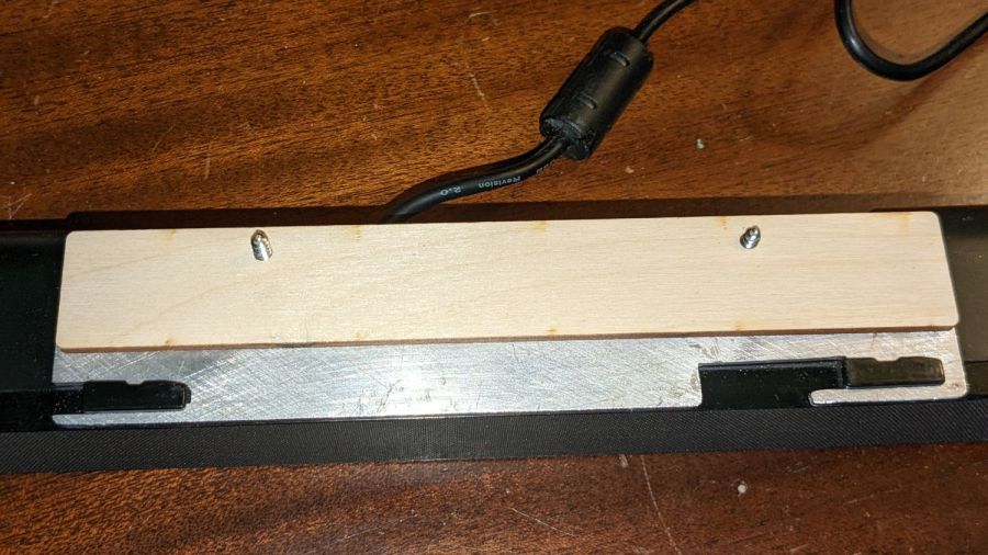
Dell sound bar mount – plate installed
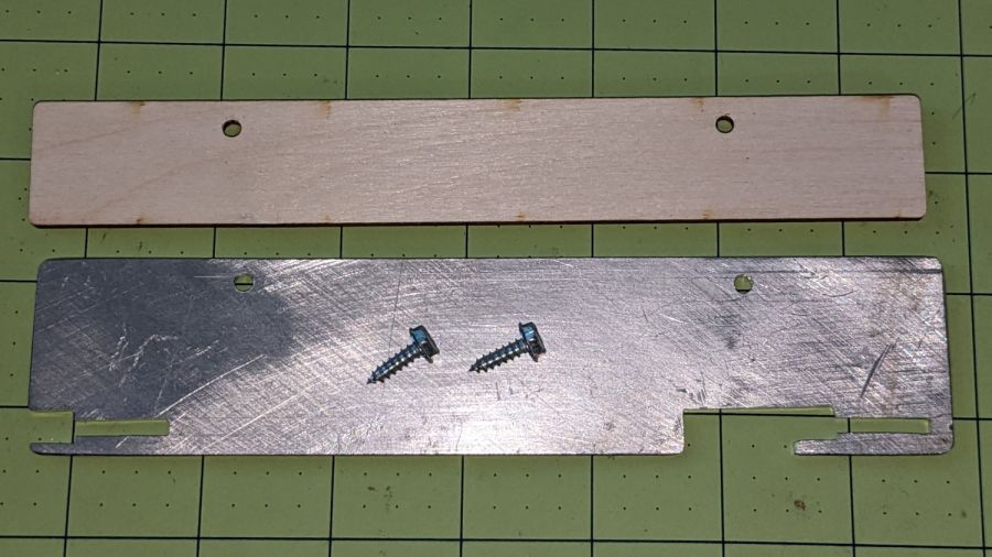
The bar’s plastic bits require a few millimeters of clearance above the sheet, now provided by a matching plywood shape:
Dell sound bar mount – parts
A trial fit showed all the parts would fly in formation:
Dell sound bar mount – trial fit
A laser-cut cardboard template maintained alignment and spacing while I stood on my head screwing the mount in place.
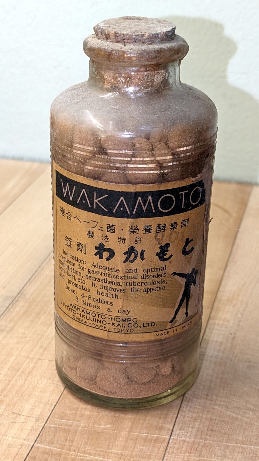
Sorting out a box of memorabilia produced a dusty bottle full of crumbled brown pills:
Vintage Wakamoto Digestive Tablets
The English part of the label:
Indication: Adequate and optimal treatment for gastrointestinal disorders, malnutrition, neurasthenia, tuberculosis, bere-beri, etc. It improves the appetite and promotes health
Dose: 4-8 tablets[,] 3 times a day
WAKAMOTO-HOMPO EIYOTO-IKUJINO-KAI, CO., LTD. SHIBA-PARK, TOKYO
My father spent several years on an all-expenses-paid trip to the South Pacific between 1943 and 1945. I have no idea what relation that bottle might have to his adventures, but the English text suggests it’s not a souvenir of those times.
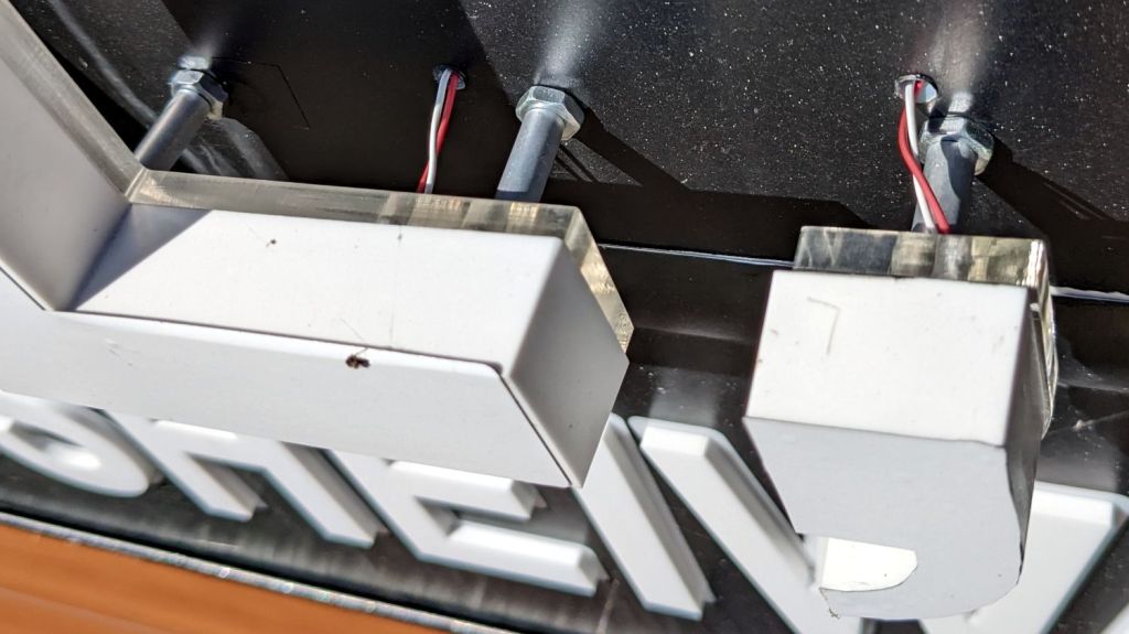
A dentist’s office has been a-building for what seems entirely too long, but the outdoor sign finally went up. Being that type of guy, I had to take a closer look at how they wired up the LEDs:
Outdoor sign LED wiring
That’s exactly as half-assed as it looks: unprotected PVC wires emerging from raw holes drilled into the backplate and burrowing into unsealed laser-cut acrylic loosely seated behind the white character boxes.
Everything you see is gonna be full of bugs in no time!
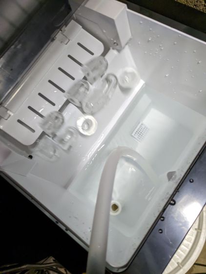
It has a drain hole in the bottom that made this whole thing practical, because a PVC pipe hot-melt-glued atop the drain maintains the water level in the reservoir without any further attention:
Silonn icemaker – drain pipe
The water line from the laser, formerly run directly into the bucket, now goes into the reservoir and through the drain into the bucket. The bucket holds about five gallons of water, with the pump submerged in the bottom.
The icemaker pumps water from the reservoir into the little icemaker tray, freezes nine little ice bullets, and scrapes them into the reservoir:
Silonn icemaker – new ice dump
It does that about every eight minutes.
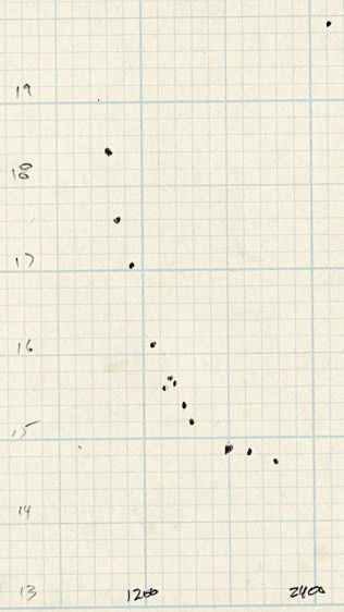
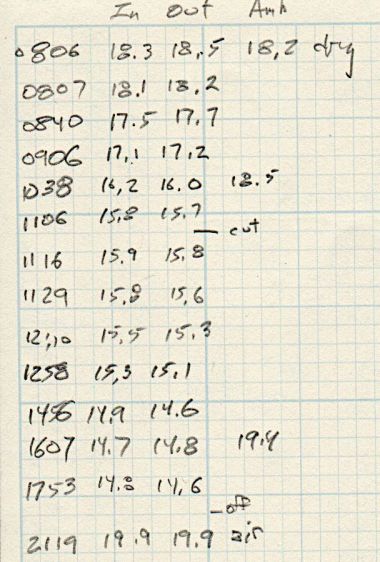
A plot of water temperature vs. time shows what happens:
Silonn icemaker – cooling water plot
It’s as exponential as you could want.
The ice bullets drop into the reservoir and melt there, the cooled water continuously flows into the bucket, and mixes with the rest of the water before being pumped back through the laser. As a result, there are no sudden water temperature changes and the laser remains perfectly happy.
Some numbers for an idea of the cooling capacity:
Freezing 28 pounds = 12.7 kg of ice a day (which, in normal use, would require me to babysit the thing overnight to empty the ice and refill the reservoir) works out to:
12.7 kg × 334 kJ/kg = 4.2 MJ
Spread across 24 hours, that’s 49 W of cooling power. There will be a bit more going into the chilled water surrounding the bullets, but most of the energy goes into the water-to-ice phase change.
Run another way, 5 gallons of water is 42 pounds. The initial cooling slope looks like 2 °C = 3.6 °F in 2 hr, which is 75 BTU/hr = 23 W. However, the water is cooling the laser (which was inert except for one brief cut) as well as the basement, plus (most importantly) there’s a water pump dissipating 20 W submerged in the bucket, so the icemaker is delivering at least 43 W, which is pretty much its rated performance.
It’s obviously incapable of keeping up with a laser doing full-time production work, but for my simple needs it seems better than dunking ice packs in the bucket.
More study (and maybe getting an air-cooled water pump) is in order …
Anything would be better than just taping some gel filters to the front of the bare photodiode package:
Laser output – photodiode kludge
Right?
I heaved the slab of ½ inch black acrylic left over from the Totally Featureless (WWVB) Clock into the laser cutter and, two passes at 90% power later, had a somewhat lumpy 32 mm donut with an 11 mm hole in the middle. Because acrylic is opaque to the IR light from a CO₂ laser (which is why it cuts so well) and black acrylic is opaque to visible light (which is what the photodiode is designed for), this is at least as good as an aluminum housing and much easier to make.
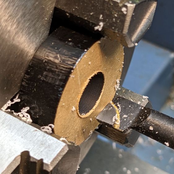
Chuck the donut into Tiny Lathe and bore out the hole:
PIN-10D photodiode filter holder – boring ID
When it’s a snug fit to ½ inch brass tube (about the same size as the photodiode’s active area), flip it around, and bore the other size out to fit the photodiode case.
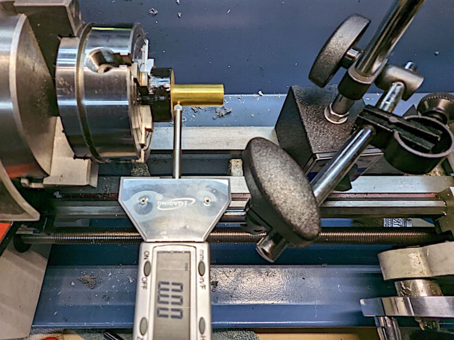
Ram the tube in place, grab the large recess, and center the tube:
[Edit: Got that backwards: I bored the big recess first.]
Skim most of the OD down, then, because I am a dolt forgot to put a spacer in there, flip it around again, get it running true (the chuck aligns the flat side):
Even though they’re pretty much transparent to thermal IR, a focused IR laser beam cuts them just fine. The little tab at 6 o’clock (remember round clocks with hands?) keeps the cut circle from falling out.
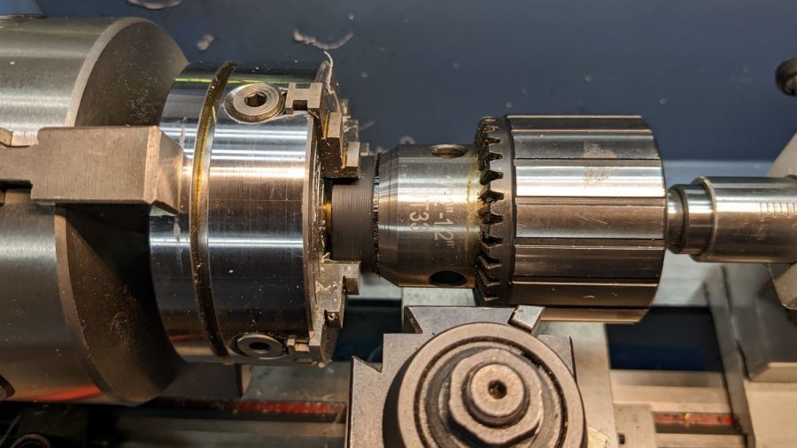
Drill & tap for an M3 setscrew to hold the photodiode in place:
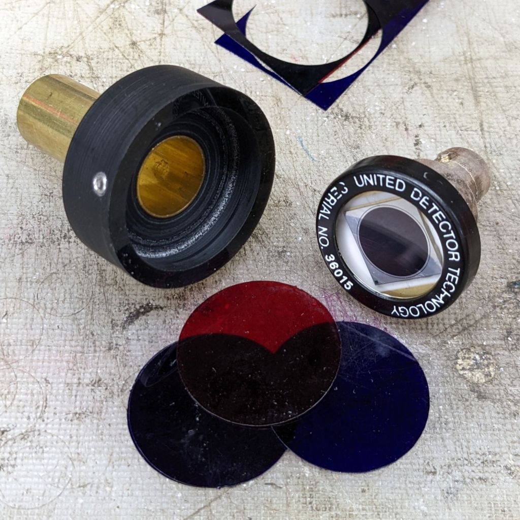
PIN-10D photodiode filter holder – parts
Put them all together:
PIN-10D photodiode filter holder – assembled
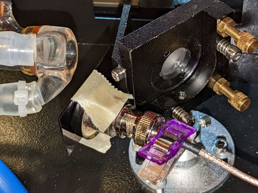
I must conjure a better mount for the thing, because this is way too precarious:
PIN-10D photodiode filter holder – test install
Early results suggest it works better than the previous hack job, without ambient light sneaking around the edges of the filter pack.